
Related Manuals for FLENDER N-BIPEX BWN


Summary of Contents for FLENDER N-BIPEX BWN
- Page 1 N-BIPEX Assembly and operating instructions M3401-02en Edition 09/2022 BWN, BWT, BNT...
- Page 2 Original assembly and operating instructions M3401-02 Edition 09/2022 20/10/2022 Copyright (©2022 Flender GmbH) 09:25:36...
-
Page 3: Table Of Contents
Table of contents Introduction...............................11 Legal information ........................11 About these instructions......................12 Text attributes ..........................12 Copyright..........................13 Safety instructions ...........................15 General information .........................15 Intended use ..........................17 Safety instructions for a coupling for use in potentially explosive atmospheres ...... 17 2.3.1 Marking ............................17 2.3.2 Conditions of use ........................18 General warning notices ......................19 Description ..............................21... - Page 4 Table of contents Operation..............................37 Normal operation of the coupling .....................37 Faults - causes and rectification ....................37 7.2.1 Procedure in the event of malfunctions..................37 7.2.2 Identifying the fault cause ......................37 7.2.2.1 Possible faults ..........................38 7.2.2.2 Possible causes ........................39 7.2.2.2.1 Unsuitable coupling........................39 7.2.2.2.2 Assembly-related causes ......................39 7.2.2.2.3...
- Page 5 Table of contents Tightening torques and widths A/F ..................62 Tightening procedure .......................62 Cam rings..........................63 A.5.1 Use and storage of the cam rings ....................63 A.5.2 N-BIPEX cam ring (50) ......................63 Declaration of Conformity........................65 UK Declaration of Conformity ....................65 M3401-02en Edition 09/2022...
- Page 6 Table of contents Edition 09/2022 M3401-02en...
- Page 7 List of tables Table 2-1 General warnings ........................15 Table 2-2 Temperature classes (TX) for explosive atmospheres as a result of gases, vapours or mists ............................18 Table 2-3 Maximum surface temperature (TX) for an explosive atmosphere as a result of dust/air mixtures............................18 Table 4-1 Types of preservative agents for long-term storage..............24 Table 5-1 Recommended assigned fits for bores with parallel key connection..........26 Table 5-2...
- Page 8 List of tables Edition 09/2022 M3401-02en...
- Page 9 List of figures Figure 3-1 BWN type ..........................21 Figure 3-2 BWT type ...........................22 Figure 3-3 BNT type ...........................22 Figure 4-1 Transport symbols........................23 Figure 5-1 Tolerances for the finished bore in coupling part 1/2 (1 or 2).............27 Figure 5-2 Diameter and axial position of the threaded hole in the hub ............28 Figure 5-3 Position of the balancing bore for single-plane balancing ............29 Figure 5-4...
- Page 10 List of figures Edition 09/2022 M3401-02en...
-
Page 11: Introduction
Introduction Legal information 1.1 Legal information Warning system These instructions contain information you must observe for your own personal safety as well as to avoid damage to property and persons. The information regarding your personal safety is highlighted with a warning triangle. Information exclusively regarding property dam- age alone is not marked with a warning triangle. -
Page 12: About These Instructions
Please note the following: WARNING Flender products are only suitable for the uses set out in the catalogue and associated technical documentation. If third-party products and components are used, these must be recommended and/or authorised by Flender. Safe and flawless operation of the products requires proper transport, proper storage, setup, assembly, installation, commissioning, operation and maintenance. -
Page 13: Copyright
(1) Numbers in brackets are part numbers. Copyright 1.4 Copyright The copyright for these instructions is held by Flender. These instructions must not be used wholly or in parts without our authorisation or be given to third parties. If you have any technical queries, please contact our factory or one of our service outlets (refer to Service and support (Page 47)). - Page 14 Introduction 1.4 Copyright Edition 09/2022 M3401-02en...
-
Page 15: Safety Instructions
Only the knowledge of these instructions can avoid faults on the coupling and ensure fault- free and safe operation. Non-adherence to the instructions can cause product or property damage or personal injury. Flender does not accept any liability for damage or operating fail- ures that are due to non-adherence to these instructions. -
Page 16: Table 2-1 General Warnings
Safety instructions 2.1 General information ANSI Warning Warning – hand injuries Explosion protection approval Table 2-1: General warnings Explanation regarding regulation 2008 No. 1597 The couplings described here are “components” in accordance with the regulation 2008 No. 1597 and do not require a UK declaration of incorporation. Explosion Protection Directive The term “Explosion protection regulations”... -
Page 17: Intended Use
• Do not make any modifications to the coupling that go beyond the permissible machining described in these instructions. This also applies to touch protection facilities. • Use only original replacement parts from Flender. Flender only accepts liability for ori- ginal replacement parts from Flender. -
Page 18: Conditions Of Use
Safety instructions 2.3 Safety instructions for a coupling for use in potentially explosive atmospheres 2.3.2 Conditions of use 2.3 Safety instructions for a coupling for use in potentially explosive atmospheres Note also the material-dependent permissible ambient temperature of the cam rings (50) in accordance with section N-BIPEX cam ring (50) (Page 63). -
Page 19: General Warning Notices
Safety instructions 2.4 General warning notices • If you want to use a coated coupling in potentially explosive atmospheres, please note the requirements concerning the conductivity of the paint and the limitation on the paint layer thickness applied in accordance with EN 80079-36. No build-up of electrostatic charges is to be expected with a paint layer thickness of less than 200 μm. - Page 20 Safety instructions 2.4 General warning notices DANGER Danger from hot coupling parts Risk of injury due to hot surfaces. Hot coupling parts can lead to an explosion in potentially explosive atmospheres. • Wear suitable protective equipment (gloves, safety goggles). • Ensure that the area is not at risk of explosion.
-
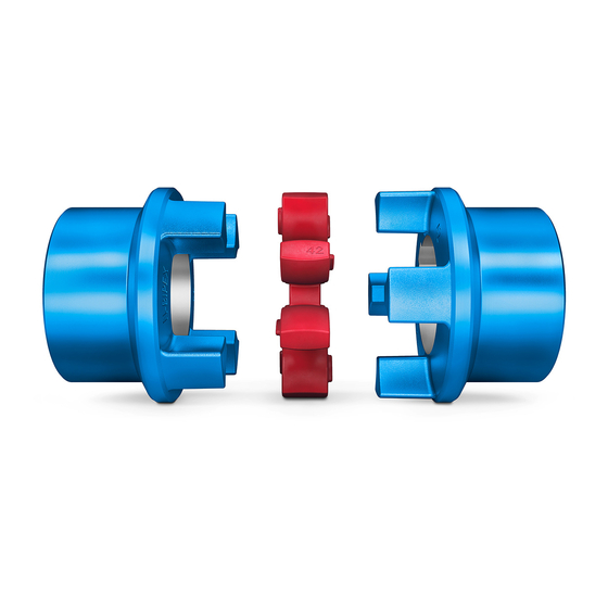
Page 21: Description
These instructions describe the assembly and operation of a N-BIPEX coupling arranged ho- rizontally with a shaft-hub connection made by a cylindrical or conical bore with parallel key, or with TAPER clamping bush with parallel key. Please consult Flender if you want to use a different type of installation. -
Page 22: Figure 3-2 Bwt Type
Description Figure 3-2: BWT type 3/4 Coupling part 3 or 4 Cam ring 101 TAPER clamping bush 102 TAPER clamping bush Figure 3-3: BNT type Coupling part 1/2 3/4 Coupling part 3 or 4 Cam ring 102 TAPER clamping bush Edition 09/2022 M3401-02en... -
Page 23: Application Planning
Application planning Check the delivery for damage and for completeness. Report any damage and/or missing parts to Flender immediately. The coupling is delivered in individual parts and preassembled groups. Preassembled groups may not be dismantled. Transport of the coupling 4.1 Transport of the coupling... -
Page 24: Table 4-1 Types Of Preservative Agents For Long-Term Storage
Application planning 4.2 Storage of the coupling • Do not store the coupling together with corrosive chemicals, acids, caustic solutions, etc. • If the coupling contains elastomer components, ensure that there are no devices in the storage room that produce ozone, such as fluorescent lights, mercury vapour lamps or high-voltage electrical equipment. -
Page 25: Assembly
• Balancing the coupling (Page 29) Information The customer is responsible for execution of the finishing work on the coupling. Flender shall have no liability whatsoever for claims under warranty arising from finishing work that has not been carried out adequately. -
Page 26: Milling The Finished Bore
Assembly 5.1 Preparatory work 5.1.1 Milling the finished bore 5.1 Preparatory work The diameter of the finished bore depends on the shaft used. Recommended assigned fits In the following table you can find the recommended assigned fits for bores with a parallel key connection. -
Page 27: Milling The Parallel Keyway
The coupling part 1/2 (1 or 2) is secured by a set screw or an end plate to prevent axial movements. Please consult Flender if you want to use an end plate. Note the following when using a set screw: •... -
Page 28: Table 5-2 Tapped Hole, Tightening Torque And Width A/F
Assembly 5.1 Preparatory work Diameter and axial position of the threaded hole in the hub The following diagram shows the axial position of the threaded hole. Figure 5-2: Diameter and axial position of the threaded hole in the hub The following table contains the values for the diameter and axial position of the threaded hole depending on the coupling size. -
Page 29: Balancing The Coupling
Assembly 5.1 Preparatory work Selection of the set screw CAUTION Physical injury Danger of injury from protruding set screw. • Please observe the information about selecting the set screw. Use set screws in accordance with ISO 4029 with a toothed cup point. The size of the set screw is determined by the bore made. -
Page 30: Assembling The Coupling
Assembly 5.2 Assembling the coupling Figure 5-4: Position of the balancing bore for two-plane balancing ① Balancing bore Assembling the coupling 5.2 Assembling the coupling NOTICE Property damage Damage to the elastomer components from cleaning agents. • Ensure that the elastomer components do not come into contact with cleaning agents. NOTICE Property damage Damage to the shaft end, the coupling parts, the TAPER clamping bush and/or the parallel... -
Page 31: Assembling Coupling Part 3 (3) Or 4 (4)
Assembly 5.2 Assembling the coupling 4. Mount the coupling part 1/2 (1 and/or 2) on the shaft. WARNING Danger due to bursting of the coupling If you do not observe the information stipulated here when assembling coupling parts with a tapered bore, then this can cause the coupling to burst in operation. There is a risk of fatal injury from flying fragments. -
Page 32: Aligning The Coupling
Assembly 5.3 Aligning the coupling 3. Line up the half blind holes of the TAPER clamping bush (101) or (102) with the half tapped holes of the coupling part 3 (3) or 4 (4). 4. Apply a small quantity of liquid screw locking agent (e.g. Loctite 243 medium strength) to the screws of the TAPER clamping bush. -
Page 33: Possible Misalignment
Assembly 5.3 Aligning the coupling 5.3.2 Possible misalignment 5.3 Aligning the coupling The following types of misalignment can occur: Figure 5-5: Possible misalignment ① Axial misalignment (ΔKa) ② Angular misalignment (ΔKw) ③ Radial misalignment (ΔKr) 5.3.2.1 Axial misalignment 5.3 Aligning the coupling Set the axial misalignment ΔKa to a value within the permissible tolerance range of dimen- sion S2. - Page 34 Assembly 5.3 Aligning the coupling You can find the permissible radial misalignment ΔKr in section Shaft misalignment val- perm ues during operation (Page 59). Edition 09/2022 M3401-02en...
-
Page 35: Commissioning
Commissioning DANGER Danger due to igniting deposits During use in potentially explosive atmospheres deposits from heavy metal oxides (rust) can ignite due to friction, impact or friction sparks and lead to an explosion. • Ensure through the use of an enclosure or other suitable measures that the deposition of heavy metal oxides (rust) on the coupling is not possible. - Page 36 Commissioning Edition 09/2022 M3401-02en...
-
Page 37: Operation
Operation Normal operation of the coupling 7.1 Normal operation of the coupling The coupling runs quietly and shock-free during normal operation. Faults - causes and rectification 7.2 Faults - causes and rectification A form of behaviour which is different to normal operation is classed as a fault and has to be rectified immediately. -
Page 38: Possible Faults
Operation 7.2 Faults - causes and rectification WARNING Physical injury Injury from rotating parts. • Only carry out work on the coupling when it is not moving. • Secure the drive unit against being operated accidentally. • Attach a notice to the switch stating clearly that work is being carried out on the coup- ling. -
Page 39: Possible Causes
Operation 7.2 Faults - causes and rectification Fault Cause Rectification Presence of vibration Incorrect assembly of the coupling. Reassemble the coupling in accord- ance with these instructions. Check the possible causes given in sections Assembly-related causes Please observe all the stipulations and (Page 39) and Specific installation-re- requirements given in chapter As- lated and maintenance-related causes... -
Page 40: Maintenance-Related Causes
7.2 Faults - causes and rectification • Stipulated maintenance intervals not adhered to. • Spare parts that were used were not original spare parts from Flender. • Flender spare parts that were used were old or damaged. • Leak in the area of the coupling not detected so that chemically aggressive substances damage the coupling. - Page 41 Operation 7.2 Faults - causes and rectification 3. Check the locking elements that prevent axial movements and correct these as required. 4. Realign the coupling. M3401-02en Edition 09/2022...
- Page 42 Operation 7.2 Faults - causes and rectification Edition 09/2022 M3401-02en...
-
Page 43: Servicing
Servicing Maintenance intervals 8.1 Maintenance intervals DANGER Danger due to bursting of the coupling The coupling can burst if the maintenance intervals are not adhered to. There is a risk of fatal injury from flying fragments. Bursting of the coupling can lead to an explosion in po- tentially explosive atmospheres. -
Page 44: Maximum Permissible Torsional Backlash
Servicing 8.2 Maximum permissible torsional backlash Maximum permissible torsional backlash 8.2 Maximum permissible torsional backlash In order to calculate the torsional backlash, rotate one coupling part without applying torque up to the stop. Mark both of the coupling halves in the way shown in the diagram below. Turn the coupling part in the opposite direction up to the stop. -
Page 45: Removing Coupling Part 1/2 (1 Or 2)
Servicing 8.4 Removing coupling part 1/2 (1 or 2) Removing coupling part 1/2 (1 or 2) 8.4 Removing coupling part 1/2 (1 or 2) WARNING Danger from burners and hot coupling parts Risk of injury due to burners and hot surfaces. Burners or hot coupling parts can lead to an explosion in potentially explosive atmospheres. - Page 46 Servicing 8.5 Removing coupling part 3 (3) or 4 (4) Edition 09/2022 M3401-02en...
-
Page 47: Service And Support
Customer Service addresses: Flender GmbH Schlavenhorst 100 46395 Bocholt Germany Tel.: +49 (0)2871/92-0 Fax.: +49 (0)2871/92-2596 Flender GmbH (http://www.flender.com/) More information Further information about service and support can be found on the Internet: Service & Support (https://www.flender.com/service) M3401-02en Edition 09/2022... - Page 48 Service and support 9.1 Contact Edition 09/2022 M3401-02en...
-
Page 49: Disposal
Disposal Disposal of the coupling Dispose of the coupling parts according to applicable national regulations or recycle them. M3401-02en Edition 09/2022... - Page 50 Disposal Edition 09/2022 M3401-02en...
-
Page 51: Spare Parts
By stocking the most important replacement parts at the installation site you can ensure that the coupling is ready for use at any time. Use only original replacement parts from Flender. Flender only accepts liability for original replacement parts from Flender. -
Page 52: Spare Parts Drawing And Spare Parts List
Spare parts 11.2 Spare parts drawing and spare parts list 11.2 Spare parts drawing and spare parts list 11.2 Spare parts drawing and spare parts list 11.2.1 Type BWN 11.2 Spare parts drawing and spare parts list Figure 11-1: Replacement parts drawing for BWN type Part number Designation Coupling part 1/2... -
Page 53: Type Bnt
Spare parts 11.2 Spare parts drawing and spare parts list Design A Design B Design AB Part num- Designation Part num- Designation Part num- Designation Coupling part 3 Coupling part 4 Coupling part 4 Cam ring Cam ring Cam ring TAPER clamping bush TAPER clamping bush TAPER clamping bush... - Page 54 Spare parts 11.2 Spare parts drawing and spare parts list Edition 09/2022 M3401-02en...
-
Page 55: Technical Data
Technical data Speeds, geometry data and weights Speeds, geometry data and weights In this section you can find dimension drawings and technical data for N-BIPEX couplings of the following types: • BWN type (Page 55) • BWT type (Page 56) • BNT type (Page 58) A.1.1 BWN type Speeds, geometry data and weights... -
Page 56: Bwt Type
Technical data Speeds, geometry data and weights Size Speed Weight D1 / D2 ND1 / ND2 NL1 / NL2 max. perm dev. 6,500 ± 2 6,000 ± 2.5 5,000 ± 2.5 13.8 4,000 ± 3 21.4 Table A-1: Speed, geometry data and weights for BWN type Maximum bore for parallel keyway in accordance with DIN 6885/1 Required installation space Weight applies to one coupling with maximum bore... -
Page 57: Table A-2 Speed, Geometry Data And Weights For Bwt Type
Technical data Speeds, geometry data and weights Size Speed TAPER- Weight clamping bush D1 / D2 min. max. perm dev. 14,500 ± 1.5 1008 12,500 ± 1.0 1108 10,000 ± 1.5 1108 8,500 ± 1.5 1610 7,500 ± 2.0 1615 6,500 ±... -
Page 58: Bnt Type
Technical data Speeds, geometry data and weights A.1.3 BNT type Speeds, geometry data and weights Figure A-3: BNT type Coupling part 1/2 3/4 Coupling part 3 or 4 Size Speed TAPER- Weigh clamp- bush min. max. perm dev. 14,500 ± 1.5 1008 12,500 ±... -
Page 59: Flat Groove In Taper Clamping Bushes (101), (102)
Technical data Speeds, geometry data and weights Size Speed TAPER- Weigh clamp- bush min. max. perm dev. 4,000 ± 3.0 3535 20.7 Table A-3: Speed, geometry data and weights for BNT type Maximum bore for parallel keyway in accordance with DIN 6885/1. Some bores have a flat groove. -
Page 60: Table A-5 Correction Factor
Technical data Shaft misalignment values during operation Use the following formulae to calculate the maximum permissible misalignment in your sys- tem: ΔK = ΔK · FKV perm 1,500 You can find the correction factor FKV and the values for ΔK in the following tables. Speed in rpm 1 000 1 500... -
Page 61: Table A-7 Maximum Permissible Shaft Misalignment Values During Operation For Cam Rings (50) With
Technical data Shaft misalignment values during operation Cam rings (50) with hardness 95 Shore A Size ∆K at n = 1,500 rpm 1500 ∆Kr ∆Ka ∆S2 perm perm perm 0.15 0.27 0.29 0.21 0.36 0.40 0.23 0.45 0.47 0.26 0.54 0.57 0.31 0.63 0.68 0.34 0.72... -
Page 62: Tightening Torques And Widths A/F
Technical data Tightening torques and widths A/F Tightening torques and widths A/F Tightening torques and widths A/F Size TAPER- Tightening torque T and width A/F SW Clamping bush Length Number Inch Inch 1008 28/38 1108 1210 1610 1615 55/65 2012 7/16 65/75 2517... -
Page 63: Cam Rings
Technical data Cam rings Cam rings Cam rings A.5.1 Use and storage of the cam rings Cam rings Note the following concerning the use and storage of the cam rings: • Storage possible for up to 5 years • Protect against direct sunlight, artificial light with a high UV‐content and extreme temper- atures •... - Page 64 Technical data Cam rings Edition 09/2022 M3401-02en...
-
Page 65: Declaration Of Conformity
Declaration of Conformity UK Declaration of Conformity UK Declaration of Conformity Product: FLENDER N-BIPEX® couplings Types BWN, BWT and BNT Name and address of the manufacturer: Flender GmbH Schlavenhorst 100 46395 Bocholt Germany This Declaration of Conformity is issued under the sole responsibility of the manufacturer. - Page 66 Declaration of Conformity UK Declaration of Conformity Edition 09/2022 M3401-02en...
- Page 68 N-BIPEX Assembly and operating instructions M3401-02en Edition 09/2022 Flender GmbH Alfred-Flender-Straße 77 46395 Bocholt Germany...
Need help?
Do you have a question about the N-BIPEX BWN and is the answer not in the manual?
Questions and answers