Advertisement
Quick Links
Advertisement

Related Manuals for Flash DJ Series


Summary of Contents for Flash DJ Series
- Page 1 SERIES: LED STROBE User Manual Instrukcja Obsługi Art No F9700341...
-
Page 2: Table Of Contents
Pages: 2-15 Strony: 16-29 C O N T E N T S INTRODUCTION SAFETY INFORMATION PRODUCT INFORMATION INSTALLATION CONNECTION DMX CHART WARNING! Use clamp to rig the fixture. WARNING! When clamping the fixture to a truss or other structure at any other angle than with the yoke hanging vertically downwards, use two clamps of half-coupler type. -
Page 3: Introduction
I N T R O D U C T I O N THANK YOU FOR PURCHASING LED STROBE. FOR SAFETY RE- ASONS AND TO ENSURE THE TROUBLE-FREE OPERATION, CARE- FULLY READ THE INSTRUCTIONS. S A F E T Y I N F O R M AT I O N Please keep this User Manual In the event of serious ope- for future consultation. -
Page 4: Product Information
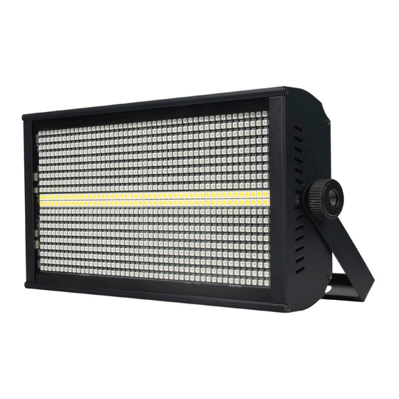
Dimming: 32 bit, (with packaging 49) 0~100 linear dimming Depth [cm]: Features: 8+8 sections 9 (with packaging 17) running + wash + flash Weight [kg]: 3,6 Operating temperature: Weight with packaging [kg]: 4,6 -30°C ~ 50°C Type of packaging: Carton Box... -
Page 5: Connection
position and orientation of the brackets and suitable clamps. fixture to minimize pooling. Fasten a safety cable between Two quarter-turn brackets are the support structure and the supplied with the fixtre if it is attachment point on the fixture. to be flown above the ground. The safety cable must be able to Rig the fixture to a support truss bear at least 10 times the weight... - Page 6 Diagram of connection of devices by DMX cable. Controller DMX 512 DMX 512 120Ω IMPORTANT! The maximum number of devices connected in series via power cable is 5 pcs. The connection is performed using power cable with powerCON con- nector (included). The device must be operated by qualified personnel. CAUTION! In the case of cable damage do not attempt to repair.
- Page 7 Menu function Press the menu key after power on, and the menu will appear in turn. Press the up or down key to modify the function parameters, and press the OK key to save the current function and parameters (with power down memory after saving).
-
Page 8: Dmx Chart
D M X C H A R T 4 CH DATA Function Description 000-255 Red linear dimming 000-255 Green linear dimming 000-255 Blue linear dimming 000-255 White linear dimming 11 CH DATA Function Description 000-255 Total dimmming 000-255 RGB strobe 000-255 RGB mode (see: VI mode effect) 000-255... - Page 9 32 CH DATA Function Description 000-255 R Section 1 Red linear dimming 000-255 G Section 1 Green linear dimming 000-255 B Section 1 Blue linear dimming 000-255 R Section 2 Red linear dimming 000-255 G Section 2 Green linear dimming 000-255 B Section 2 Blue linear dimming ...
- Page 10 39 CH DATA Function Description 000-255 Total dimming 000-255 RGB strobe 000-255 RGB mode (see: VI, mode effect) 000-255 RGB mode speed 000-255 R section 1 Red linear dimming 000-255 G section 1 Green linear dimming 000-255 B section 1 Blue linear dimming ...
- Page 11 Mode effect CH value Mode code Effect No effect Green 9-11 Blue 12-14 15-17 18-20 21-23 24-26 Comprehensive mode code 1-7 cycle. 27-29 Gradual change 30-32 Pulse change 33-35 One section Red running 36-38 One section Green running 39-41 One section Blue running 42-44 One section Red Green running 45-47...
- Page 12 CH value Mode code Effect 96-98 One section Green and Blue refreshed 99-101 One section RGB refreshed 102-104 Integrated mode code 27-33 cycle 105-107 A section of Red at the head and tailrefresh back and forth. 108-110 A section of Green at the head and tailrefresh back and forth. 111-113 A section of Blue at the head and tailrefresh back and forth.
- Page 13 CH value Mode code Effect 192-194 Two square BG running 195-197 Two square RGB running 198-200 Integrated mode code 59-65 cycle 201-203 A remnant of Red running 204-206 A remannt of Green running 207-209 A remnant of Blue running 210-212 A remnant of RG running 213-215 A remnant of RB running...
- Page 14 White light mode effect CH value Mode code Effect No effect 6-11 First white 12-17 Second white 18-23 Third section white 24-29 Fifth white 30-35 Sixth white 36-41 Seventh paragraph white 42-47 Eight white 48-53 A section white runs from left to right 54-59 A section white runs from right to left 60-65...
- Page 15 CH value Mode code Effect 180-185 White light waves from left to right 186-191 White light waves from right to left 192-197 A section of white light at both ends converges in the middle Separate a section of white light wave from the middle to both 198-203 ends 204-209...
- Page 16 S P I S T R E Ś C I WPROWADZENIE INFORMACJE DOTYCZĄCE BEZPIECZEŃSTWA INFORMACJE O PRODUKCIE INSTALACJA POŁĄCZENIE TABLICA DMX OSTRZEŻENIE! Do zamocowania urządzenia należy użyć zacisku. OSTRZEŻENIE! Podczas mocowania urządzenia do kratownicy lub innej konstrukcji pod innym kątem niż z jarzmem zwisającym pionowo w dół, na- leży użyć...
- Page 17 W P R O W A D Z E N I E DZIĘKUJEMY ZA ZAKUP LED STROBE. ZE WZGLĘDÓW BEZPIE- CZEŃSTWA I W CELU ZAPEWNIENIA BEZAWARYJNEJ PRACY NA- LEŻY UWAŻNIE PRZECZYTAĆ INSTRUKCJĘ. IN FO RMACJ E DOTYCZ ĄC E B E ZP IEC Z EŃ ST WA Niniejszą...
- Page 18 I N F O R M A C J A O P R O D U K C I E AC 100~240V 50/60Hz Częstotliwość stroboskopowa: Moc: 250W 1~30 Hz Kulki lampy: 864 szt. 5050 Obudowa: Metalowa, czarna LED RGB + 96 sztuk białych ryb połączenia: DMX512, diod LED PowerCON IN/OUT,...
- Page 19 Sprzęt musi być montowany stępnym dla osób postronnych, przez profesjonalistów. Musi być tak aby nikt nie przechodził obok zamocowany w miejscu niedo- niego ani pod nim. P O Ł A C Z E N I E Urządzenie wyposażone jest w następujące interfejsy: 1.
- Page 20 Schemat połączenia urządzeń kablem DMX. Controller DMX 512 DMX 512 120Ω WAŻNE! Maksymalna liczba urządzeń podłączonych pomiędzy sobą za pomocą kabla zasilającego wynosi 5 sztuk. Podłączenie odbywa się za pomocą kabla zasilającego ze złączem powerCON (w zestawie). Urządzenie musi być obsługiwane przez wy- kwalifikowany personel.
- Page 21 Funkcje Menu Po włączeniu zasilania należy nacisnąć przycisk menu, co spowoduje wyświetlenie menu. Naciśnij przycisk w górę lub w dół, aby zmodyfi- kować parametry funkcji, a następnie naciśnij przycisk OK, aby zapisać bieżącą funkcję i parametry (z wyłączeniem pamięci po zapisaniu). MENU OPIS Zmodyfikuj kod adresu (A001-A512) w górę...
- Page 22 TA B L I C A D M X 4 CH Wartość Opis funkcji 000-255 Red linear dimming 000-255 Green linear dimming 000-255 Blue linear dimming 000-255 White linear dimming 11 CH Wartość Opis funkcji 000-255 Total dimmming 000-255 RGB strobe 000-255 RGB mode (see: VI mode effect) 000-255...
- Page 23 32 CH Wartość Opis funkcji 000-255 R Section 1 Red linear dimming 000-255 G Section 1 Green linear dimming 000-255 B Section 1 Blue linear dimming 000-255 R Section 2 Red linear dimming 000-255 G Section 2 Green linear dimming 000-255 B Section 2 Blue linear dimming ...
- Page 24 39 CH Wartość Opis funkcji 000-255 Total dimming 000-255 RGB strobe 000-255 RGB mode (see: VI, mode effect) 000-255 RGB mode speed 000-255 R section 1 Red linear dimming 000-255 G section 1 Green linear dimming 000-255 B section 1 Blue linear dimming ...
- Page 25 Efekt trybu wartość CH Kod trybu Efekt No effect Green 9-11 Blue 12-14 15-17 18-20 21-23 24-26 Comprehensive mode code 1-7 cycle. 27-29 Gradual change 30-32 Pulse change 33-35 One section Red running 36-38 One section Green running 39-41 One section Blue running 42-44 One section Red Green running 45-47...
- Page 26 wartość CH Kod trybu Efekt 99-101 One section RGB refreshed 102-104 Integrated mode code 27-33 cycle 105-107 A section of Red at the head and tailrefresh back and forth. 108-110 A section of Green at the head and tailrefresh back and forth. 111-113 A section of Blue at the head and tailrefresh back and forth.
- Page 27 wartość CH Kod trybu Efekt 192-194 Two square BG running 195-197 Two square RGB running 198-200 Integrated mode code 59-65 cycle 201-203 A remnant of Red running 204-206 A remannt of Green running 207-209 A remnant of Blue running 210-212 A remnant of RG running 213-215 A remnant of RB running...
- Page 28 Efekt trybu światła białego CH value Mode code Effect No effect 6-11 First white 12-17 Second white 18-23 Third section white 24-29 Fifth white 30-35 Sixth white 36-41 Seventh paragraph white 42-47 Eight white 48-53 A section white runs from left to right 54-59 A section white runs from right to left 60-65...
- Page 29 CH value Mode code Effect 192-197 A section of white light at both ends converges in the middle Separate a section of white light wave from the middle to both 198-203 ends 204-209 A white light runs back and forth at four intervals 210-215 Four section conection white light runs back and forth 216-221...
- Page 30 FLASH-BUTRYM Sp.j. Skarbimierzyce 18 · 72-002 Dołuje · POLAND WWW.FLASH-BUTRYM.PL...
Need help?
Do you have a question about the DJ Series and is the answer not in the manual?
Questions and answers