Table of Contents
Advertisement
Advertisement
Table of Contents

Related Manuals for Arista 7050 Series


Summary of Contents for Arista 7050 Series
-
Page 3: Table Of Contents
Contents Contents Chapter 1: Overview................1 1.1 Scope............................1 1.2 Receiving and Inspecting the Equipment................1 1.3 Installation Process.........................1 1.4 Safety Information........................2 1.5 Obtaining Technical Assistance..................... 2 1.6 Specifications.......................... 2 Chapter 2: Preparation................5 2.1 Site Selection..........................5 2.2 Tools and Parts Required for Installation................6 2.3 Electrostatic Discharge (ESD) Precautions................ - Page 4 B.2 Cables...........................34 B.3 Ground Extender Kit (Optional)....................34 Appendix C: Front Panel..............35 C.1 Port-Speed Groups......................35 C.2 Front Panels.........................35 Appendix D: Rear Panel............... 43 Appendix E: Maintenance and Field Replacement......45 E.1 Considerations........................45 E.2 Power Supplies........................45 E.2.1 Removing a Power Supply..................45 E.2.2 Installing a Power Supply..................46 E.3 Fan Modules.........................46 E.3.1 Removing a Fan Module..................
-
Page 5: Chapter 1: Overview
Chapter 1 Overview Scope This guide is intended for properly trained service personnel and technicians who need to install Arista Networks Data Center Switches. DCS-7050QX-32S DCS-7050TX-48 DCS-7050QX2-32S DCS-7050TX-64 DCS-7050SX-64 DCS-7050TX-72 DCS-7050SX-72 DCS-7050TX-72Q DCS-7050SX-72Q DCS-7050TX-96 DCS-7050SX2-72Q DCS-7050SX-96 DCS-7050CX3-32S DCS-7050SX3-48YC12 DCS-7050SX3-48YC8 DCS-7050CX3M-32S... -
Page 6: Safety Information
Aucune pièce réparable par l'utilisateur à l'intérieur. Confiez toute réparation à un technicien qualifié. Specifications List of specifications of Arista Data Center modular switches and components covered by this guide. Table 1: Switch Specifications (Dimensions and Weights) Switch Size (W x H x D) - Page 7 Overview DCS-7050QX-32S 48.3 x 4.4 x 40.6 cm (19 x 1.75 x 16 inches) 9.1 kg (20.1 lbs.) DCS-7050TX-48 48.3 x 4.4 x 40.6 cm (19 x 1.75 x 16 inches) 7.7 kg (17.0 lbs.) DCS-7050QX2-32S 48.3 x 4.4 x 40.6 cm (19 x 1.75 x 16 inches) 9.1 kg (20.1 lbs.) DCS-7050TX-64 48.3 x 4.4 x 40.6 cm (19 x 1.75 x 16 inches)
- Page 8 -48 to -60 VDC, 30 A Note: All PSU models are not supported by all switches. Some switches described in this guide could use power supplies that may no longer be available. Contact your local Arista representative for more information.
-
Page 9: Chapter 2: Preparation
Chapter 2 Preparation Site Selection Describes the location specifications. The following criteria should be considered when selecting a site to install the switch: • Temperature and Ventilation: For proper ventilation, install the switch where there is ample airflow to the front and back of the switch. The ambient temperature should not go below 0° or exceed 40°C. -
Page 10: Tools And Parts Required For Installation
Figure 1: Airflow Direction Labels and Handles Power supply module Fan module 4 Fan module 3 status LED 1 label Fan module 1 Power supply module 2 Fan module 2 status LED label Fan module 2 Fan module handle Fan module 1 status LED Fan module 3 Fan module 4 status LED 12 PSU 1 status LED... -
Page 11: Electrostatic Discharge (Esd) Precautions
Preparation • Screwdriver Accessory kit does not include screws for attaching the switch to the equipment rack. When installing the switch into an equipment rack with unthreaded post holes, nuts are also required to secure the switch to the rack posts. Electrostatic Discharge (ESD) Precautions Observe these guidelines to avoid ESD damage when installing or servicing the switch. -
Page 13: Chapter 3: Rack Mounting The Switch
Chapter 3 Rack Mounting the Switch Important: The rack mounting procedure is identical for all switches covered by this guide. Illustrations in this chapter depict the mounting of a DCS-7050QX-32S switch. Les procédure de montage du bâti est identique pour tous les commutateurs visés par ce guide. -
Page 14: Attaching Mounting Brackets To The Two-Post Chassis
Figure 3: Improper Bracket Mount Examples for Two-Post Rack Mount 3.1.1 Attaching Mounting Brackets to the Two-Post Chassis The following image displays the front bracket alignment for mounting the switch into a four-post rack. Figure 4: Attaching the Mounting Brackets to the Switch Chassis This procedure attaches mounting brackets to the switch chassis as depicted by Figure 4: Attaching the Mounting Brackets to the Switch Chassis... -
Page 15: Four-Post Rack Mount
Rack Mounting the Switch Figure 5: Inserting the Switch into the Rack After completing the two-post rack mount, proceed to Cabling the Switch. Four-Post Rack Mount Discusses the four-post racking option. The switch is mounted onto a four-post rack by assembling two rails onto the rear posts, sliding the switch onto the rails, then securing the switch to the front posts. -
Page 16: Attaching Mounting Brackets To The Four-Post Chassis
Figure 7: Improper Bracket Mount Example for Four-Post Rack Mount Bracket not attached by at least 5 pins 3.2.1 Attaching Mounting Brackets to the Four-Post Chassis The following image displays the front bracket alignment for mounting the switch into a four-post rack. Figure 8: Attaching the Mounting Brackets to the Switch Chassis This procedure attaches mounting brackets to the switch chassis as depicted by Figure 4: Attaching... - Page 17 Rack Mounting the Switch Figure 9: Attaching the Four-Post Mounting Brackets to the Switch Chassis Step 1 Bracket clip (attached) Step 2 Bracket clip (aligned) Step 3 This procedure attaches the rails to a four post rack: 1. Slide a rail-rod into a rail-slide (Figure 10: Assembling the Rails) until the rail clip makes an audible click.
-
Page 18: Attaching The Switch To The Rack
Figure 11: Attaching the Rails Detail A Detail B 3.2.3 Attaching the Switch to the Rack After the rails are installed, the switch slides on the rails into the rack. Each bracket includes a thumb screw that attaches the switch to the rail. 1. - Page 19 Rack Mounting the Switch Figure 13: Attaching the Switch to the Rack Posts After completing the four-post rack mount, proceed to Cabling the Switch.
-
Page 21: Chapter 4: Cabling The Switch
Chapter 4 Cabling the Switch Grounding the Switch After mounting the switch into the rack, this section descusses how to connect the switch to the data center ground. Figure 14: Earth Grounding Pad Sockets for Models without Management Ports on the Rear Panel displays the location of the grounding pads located on the bottom corners of the rear panel for the models that have no management ports on the rear panel. -
Page 22: Grounding Adapter Assembly (Dcs-7050Sx3-48Yc8)
Figure 16: Earth Grounding Adapter for DCS-7050SX3-48YC8 Grounding Adapter Assembly (DCS-7050SX3-48YC8) Use the following steps to assemble and attach a grounding assembly to the chassis before mounting it into the rack. Figure 17: Earth Grounding Adapter Assembly for DCS-7050SX3-48YC8 shows the exploded and assembled views. -
Page 23: Ac Power Supplies
Cabling the Switch Installation de cet équipement doit être conformes aux codes électriques locaux et nationaux. Si nécessaire, consulter les organismes de réglementation appropriés et des autorités de contrôle pour assurer la conformité. The switch operates with two installed power supplies. At least one power supply must connect to a power source. -
Page 24: Dc Power Supplies
Figure 19: PWR-1011-AC-RED AC Power Supply Handle Power supply status Release The power supplies require power cables that comply with IEC-320. The accessory kit provides two IEC-320 compliant power cables with appropriate connectors for the PSUs. 4.3.2 DC Power Supplies The following DC power supplies are supported. -
Page 25: Connecting The Dc Power Supply
Cabling the Switch Figure 21: PWR-1011-DC DC Power Supplies Power supply status Battery Return Terminal cover -48V Protective Earth Release Handle Important: A disconnect device must be provided as part of the installation. Un dispositif de sectionnement doit être fourni dans le cadre de l'installation. Important: Ensure power is removed from DC circuits before performing any installation actions. - Page 26 Table 5: Wiring, Lug, and Tightening Torques for DC PSUs Wire Size Lug Type Tightening Torque (AWG) N • m in. • lbs. PWR-500-DC 14 or larger 2.0 or larger ring or spade/ fork PWR-511-DC 10 - 12 6.0 - 4.0 ring PWR-1011-DC 6 - 8...
-
Page 27: Connecting Serial And Management Cables
Cabling the Switch Connecting Serial and Management Cables This section discusses the serial and management cables requirements and connections. The accessory kit includes the following cables: • RJ-45 to DB-9 serial adapter cable. • RJ-45 Ethernet cable. Either the front panel or the rear panel has the console, management, and USB ports. Front Panel Rear Panel display the front and rear panels of all switches covered by this guide. - Page 28 Connect the front or rear panel ports as follows: • Console (Serial) Port: Connect to a PC with the RJ-45 to DB-9 serial adapter cable. The switch uses the following default settings: • 9600 baud • No flow control • 1 stop bit •...
-
Page 29: Chapter 5: Configuring The Switch
Chapter 5 Configuring the Switch Arista switches ship from the factory in Zero Touch Provisioning (ZTP) mode. ZTP configures the switch without user intervention by downloading a startup configuration file or a boot script from a location specified by a DHCP server. - Page 30 When the management port IP address is configured, use this command to access the switch from a host, using the address configured in Step 9: ssh admin@192.0.2.8 Refer to the Arista Networks User Manual for complete switch configuration information.
-
Page 31: Appendix A: Status Indicators
Appendix A Status Indicators This section discusses the several status indicators, their location, and the meaning of their display status. Front Indicators Front panel LEDs are located on the right side of the chassis and display system, fan, and power supply status. -
Page 32: Port Indicators
Table 7: Switch Indicators LED States (Front) LED Name LED State Device Status System Status LED Blinking Green System is powering up. Green Normal operations. Due to power supply and fan redundancy, this LED will remain green if a single fan or power supply is missing or in a failed state. -
Page 33: Rear Status Indicators
Status Indicators 2 Port 3 LEDs 4 Port 1 LEDs Table 8: Port LED States (Front) provides status conditions that correspond to port LED states. Port LED behavior for QSFP+ and SFP+ ports is consistent. Table 8: Port LED States (Front) LED State Status Port link is down. - Page 34 Figure 27: AC Power Supply Status LED Power supply status Table 10: AC Power Supply Status LED States (Rear) provides status conditions that correspond to the AC power supply status LED states. Table 10: AC Power Supply Status LED States (Rear) Power Supply State PWR-500AC-F PWR-511-AC-RED...
- Page 35 Note: You can narrow down the error condition by logging in to the switch to view the specific device state. Refer to the Arista User Manual’s Switch Environment Control chapter, under the topic Viewing Environment Status, for further information on the show environment...
-
Page 37: Appendix B: Parts List
Appendix B Parts List Each switch provides an accessory kit that contains parts that are required to install the switch. This section lists the installation parts contained in the switch accessory kit. Rack Mount Parts This section discusses the parts and accessories required for the two-post and four-post installation methods. -
Page 38: Cables
Power cables: IEC-320/C13-C14, 13 A, 250 V RJ-45 Patch Panel Cable RJ-45 to DB9 Adapter Cable Warning: All provided power cables are for use only with Arista products. Ground Extender Kit (Optional) This section describes the optional ground extender kit for NEBS compliance. -
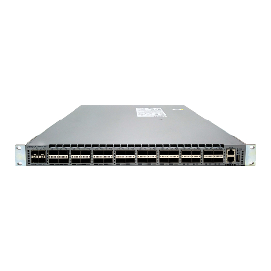
Page 39: Appendix C: Front Panel
Appendix C Front Panel This section displays the front panel of all switches covered by this guide. Note: All devices are designed to fit into a 19” rack. The appearance may be different than those shown based on the PSU and the fan modules used. Port-Speed Groups For devices that support the port-speed group feature, the groups are called out in the relevant illustrations with the ports in the group identified. - Page 40 Figure 32: DCS-7050TX-48 Console serial port Power supply 1 status Ethernet management port System status LED Power supply 2 status Port numbers Fan status LED USB port Figure 33: DCS-7050QX2-32S Console serial port Power supply 1 status Ethernet management port System status LED Power supply 2 status Port numbers...
- Page 41 Front Panel Console serial port Power supply 1 status Ethernet management port System status LED Power supply 2 status Port numbers Fan status LED USB port Figure 35: DCS-7050SX-64 Console serial port Power supply 1 status Ethernet management port System status LED Power supply 2 status Port numbers Fan status LED...
- Page 42 Figure 37: DCS-7050SX-72 Console serial port Power supply 1 status Ethernet management port System status LED Power supply 2 status Port numbers Fan status LED USB port Figure 38: DCS-7050TX-72Q System status LED Power supply 1 status USB port Fan status LED Power supply 2 status Port numbers Figure 39: DCS-7050SX-72Q...
- Page 43 Front Panel Fan status LED Power supply 2 status Port numbers Figure 40: DCS-7050TX-96 Console serial port Power supply 1 status Ethernet management port System status LED Power supply 2 status Port numbers Fan status LED USB port Figure 41: DCS-7050SX2-72Q System status LED Power supply 1 status USB port...
- Page 44 Console serial port Power supply 1 status Ethernet management port System status LED Power supply 2 status Port numbers Fan status LED USB port Figure 43: DCS-7050CX3-32S Ethernet management Power supply 1 status Console serial port port System status LED Power supply 2 status Port numbers Fan status LED...
- Page 45 Front Panel Figure 45: DCS-7050SX3-48YC8 System status LED Power supply 1 status Port numbers Fan status LED Power supply 2 status Figure 46: DCS-7050CX3M-32S Ethernet management Power supply 1 status Console serial port port System status LED Power supply 2 status Port numbers Fan status LED USB port...
- Page 46 Fan status LED Power supply 2 status Figure 48: DCS-7050SX3-48C8 System status LED Power supply 1 status Port numbers Fan status LED Power supply 2 status...
-
Page 47: Appendix D: Rear Panel
Appendix D Rear Panel All switches covered by this guide use one of the rear panels shown below. Depending on the installed power supply module, the appearance could be different from those shown. Note: All devices are designed to fit into a 19” rack. The appearance may be different than those shown based on the PSU and the fan modules used. - Page 48 Figure 51: Rear Panel for Models with Management Ports in the Rear and two Dual-fan Modules Power supply 1 status Fan module 2 handle Fan module 2 status LED Fan module 1 handle 5 Power supply 2 status Fan module 1 status LED Fan module bezel Power supply 2 Power supply 1...
-
Page 49: Appendix E: Maintenance And Field Replacement
All slots must be filled or covered with a blank for operation (even though power supply or fans may not be functional). • Before you begin, refer to the Arista Networks document Safety Information and Translated Safety Warnings available at: https://www.arista.com/en/support/product-documentation. Note: Descriptions for the removal and replacement of power supplies and fans are for a representative power supply or fan. -
Page 50: Installing A Power Supply
E.2.2 Installing a Power Supply You must make space for installing the power supply by removing an existing one (Removing a Power Supply). 1. Remove the replacement power supply from its packaging. 2. Slide the new power supply into the empty slot. 3. -
Page 51: Installing A Fan Module
Maintenance and Field Replacement E.3.2 Installing a Fan Module You must make space for installing the fan module by removing an existing one (Figure 54: Removing Fan Module 1. Remove the replacement fan from its packaging. 2. Slide the new fan module into the switch until the module is fully seated and the release lever snaps into place (Figure 55: Inserting Fan Module). -
Page 53: Appendix F: Regulatory Model Numbers
Appendix F Regulatory Model Numbers This appendix lists the regulatory model numbers (RMNs), where applicable, for the product models for the switches described in this document. Table 12: Regulatory Model Numbers and Product Numbers Regulatory Model Number (RMN) Product Number(s) AN1501 DCS-7050SX-72Q, DCS-7050SX2-72Q... -
Page 55: Appendix G: Taiwan Rohs Information
Appendix G Taiwan RoHS Information This appendix provides Taiwan RoHS information for switches covered by this guide. For Taiwan BSMI RoHS Table, go to https://www.arista.com/assets/data/pdf/AristaBSMIRoHS.pdf.
Need help?
Do you have a question about the 7050 Series and is the answer not in the manual?
Questions and answers