Page 1
Quick Start Guide 7060X5 Series Data Center Switches Arista Networks www.arista.com DOC-06886-01...
Page 2
The trademarks, logos, and service marks ("Marks") displayed in this documentation are the property of Arista Networks in the United States and other countries. Use of the Marks is subject to Arista Network Terms of Use Policy, available at www.arista.com/en/terms-of-use. Use of marks belonging to other parties is for informational...
Chapter 1 Overview This guide is intended for properly trained service personnel and technicians who need to install selected Arista Networks Data Center Switches. The following topics are covered in this section: • Scope • Receiving and Inspecting the Equipment •...
L'élimination finale de ce produit doit être effectuée conformément à toutes les lois nationales etrèglements. Obtaining Technical Assistance Any customer, partner, reseller or distributor holding a valid Arista Service Contract can obtain technical support in any of the following ways. •...
Overview Specifications List of specifications of Arista data center modular switches and components covered by this guide. Table 1: Switch Specifications (Dimensions and Weights) Switch Size (W x H x D) Weight DCS-7060X5 Series switches (1RU) DCS-7060DX5-64E 14.6 kg (32.2 lbs.) 48.3 x 4.4 x 56.6 cm (19 x 1.75...
Page 9
Note: Use only the PSU models supported by the switch. Some switches described in this guide could use power supplies that may no longer be available. Contact your local Arista representative for more information. Table 4: Switch Specifications (Power Draw)
Airflow Orientation: The fans and PSUs determine the airflow direction through the switch. The color of the visible handles or labels indicate the airflow direction. Note: The figures shown use representative Arista switches to illustrate airflow directions. • Blue Handle: Air Inlet module. The following figure shows the airflow through the switch with air inlet modules: •...
Page 11
Air Inlet modules: orient the rear panel toward the cool aisle. Most Arista switches are available in configurations to support airflow in either '-R' (Rear-to-Front, port-side air exhaust) or '-F' (Front-to-Rear, port-side air intake). For proper function, ensure that the installation direction matches the airflow configuration of the switch.
Preparation Tools and Parts Required for Installation Each switch provides an accessory kit that contains parts that are required to install the switch. In addition to the accessory kit, the following tools and equipment are required to install the switch: Two-Post Rack •...
Chapter 3 Rack Mounting the Switch Rack Mounting the Switch (1RU) The following topics are covered in this section: • Two-Post Rack Mount (1RU) Note: Use the rack-mount parts included with your switch for mounting. For heavier switches, only a four-post mount is supported. •...
Note: Deep and heavy devices could droop and cause damage to the equipment rack if front or rear mounted. Arista recommends only center mounting for switches covered in this guide when two-post mounting is required, and the switch accessory kit includes two-post mounting ears. Four- post mounting ears are different from the two-post mounting ears and should not be used for two- post mounting.
3.1.2 Inserting the Switch into the Rack (Two-Post) This procedure attaches the switch to the rack. 1. Lift the chassis into the rack. Position the flanges against the rack posts. 2. Select mounting screws that fit your equipment rack. 3. Attach the bracket flanges to the rack posts. Figure 3-3: Inserting the Switch into the Rack After completing the two-post rack mount, proceed to Cabling the...
Rack Mounting the Switch 3.2.1 Attaching Mounting Brackets to the Chassis (Four-Post) The following figure displays the front bracket alignment for mounting the switch into a four-post rack. Figure 3-4: Attaching the Mounting Brackets to the Switch Chassis (KIT-7101 shown) Figure 3-5: Attaching the Mounting Brackets to the Switch Chassis (with Deep Chassis Adapters) This procedure attaches mounting brackets to the switch chassis as depicted by the preceding figure(s).
4. Attach the deep chassis adapters as needed. To remove the mounting bracket from the chassis, lift the front edge of the mounting bracket clip with a flathead screwdriver and slide the bracket away from the front flange (opposite from the installation direction). The rest of the rack mounting steps are the same for both KIT-7001 and KIT-7101.
Rack Mounting the Switch If the rack plugs were previously removed, use bolts to attach the rail to the rack. 3. Attach the slide end of the rail to the front post by extending the rail end past the post, then contracting the rail while guiding the rack plugs into the post.
Two-Post Rack Mount (2RU) The 2RU switches covered in this guide do not support two-post rack mounting. The accessory kit contains only the four-post RMK components. Contact your local Arista Networks account representative for further information if you require two-post rack mounting.
Rack Mounting the Switch Four-Post Rack Mount (2RU) The switch is mounted onto a four-post rack by assembling two rails onto the rear posts, sliding the switch onto the rails, then securing the switch to the front posts. The installation kit provides two bracket-rail assemblies. The following four-post mounting parts are extracted from each assembly: •...
Rack Mounting the Switch 3. Slide the bracket toward the front flange until the rail locks with an audible click. Figure 3-13: Attaching the Mounting Brackets to the Switch Chassis 1 Aligned rail 2 Seated rail To remove the mounting bracket from the chassis, lift the front edge of the mounting bracket clip with a flathead screwdriver and slide the bracket away from the front flange (opposite from the installation direction).
3. Repeat Step 1 through Step 2 for the left posts. Ensure the rails are on the same horizontal level. Figure 3-14: Attaching the Rails 1 Front of right rail 3 Right rack post (rear) 2 Right rack post (front) 4 Rear of right rail 3.5.5 Attaching the Switch to the Rack...
Page 24
Rack Mounting the Switch 3. Attach the bracket flanges to the rack post using the quick-release thumb screws supplied with the brackets. Hand-tighten the thumb screws or use a Phillips #2 screwdriver. Note: Do not exceed a maximum torque of 20 in·lb nor use powered impact drivers to secure the thumb screws.
DC Power Supplies • Connecting Serial and Management Cables Note: Arista fixed switches take approximately 5 to 10 minutes to boot completely. Grounding the Switch After mounting the switch into the rack, connect the switch to the data center ground.
Cabling the Switch Grounding Adapter Assembly (1RU) The following steps assemble and attach a grounding assembly to the chassis before mounting it into the rack. The following switches support external chassis grounding. Identify the location for attaching the adapter or the lug. As shown in the following example, the attachment point is on the bottom of the chassis for the switches that support the KIT-GND-EXT-1RU grounding kit.
You must use an approved power cord compliant with local and national electrical codes or order one from Arista for use with the switch. Some power cords are shipped with each switch as part of the accessory kit. Important: Installation of this equipment must comply with local and national electrical codes.
Cabling the Switch • Redundant Power Supply Configuration: Connect power to both power supplies. • Power down the Switch: Remove all power cords and wires from the power supplies. Important: This equipment must be grounded. Never defeat the ground conductor. Cet équipement doit être mis à...
Page 29
The following image displays examples of DC power supplies. Figure 4-5: DC Power Supply Examples Important: A disconnect device must be provided as part of the installation . Un dispositif de sectionnement doit être fourni dans le cadre de l'installation. Important: Ensure power is removed from DC circuits before performing any installation actions.
Page 30
Cabling the Switch 1. Unless otherwise noted, wire size applies to -48V, Battery return, and Protective earth wires. 2. Twin #10 studs spaced for dual-hole lug with 5/8" hole spacing. 3. Strip the wires to the appropriate length for the lugs to be used. 4.
Note: The ground terminal is on the opposite side from the two terminals shown, and is not visible in the following illustration. Figure 4-7: DC PSU Connection Example Connecting Serial and Management Cables The accessory kit includes the following cables: •...
Page 32
Cabling the Switch The console, management, and USB ports are either on the front panel or the rear panel of the switch. The system status LED could be at a different location on the switch from that shown below. Figure 4-8: Management Ports and LEDs 1 System status LED 3 Activity status LED 5 USB port...
Chapter 5 Configuring the Switch Arista switches ship from the factory in Zero Touch Provisioning (ZTP) mode. ZTP configures the switch without user intervention by downloading a startup configuration file or a boot script from a location specified by a DHCP server.
Page 34
11. When the management port IP address is configured, use this command to access the switch from a host, using the address configured in step 9. ssh admin@192.0.2.8 Refer to the Arista Networks User Manual for complete switch configuration information.
Appendix A Status Indicators The following topics are covered in this section: • Front Indicators • Switch Indicators • Port Indicators • Rear Status Indicators Front Indicators Reviews the Switch and Port Indicators of the device. A.1.1 Switch Indicators Front panel LEDs are located on the right side of the chassis and display system, fan, and power supply status.
Status Indicators Table 9: Switch Indicators LED States (Front) LED Name LED State Device Status System Status LED Blinking Green System is powering up. Green Normal operations. Due to power supply and fan redundancy, this LED will remain green if a single fan or power supply is missing or in a failed state.
Table 10: Port LED States (Front) LED State Status Port link is down. Green Port link is up. Yellow Port is software disabled. Flashing Yellow Port failed diagnostics. Rear Status Indicators Fan and power supply modules are accessed from the rear panel. Each fan and power supply module contains an LED that reports the module status.
Page 38
Status Indicators The AC Power Supply Status LEDs are on the power supply modules, as displayed in Figure 28: AC Power Supply Status LED. Depending on the power supply, the LED could be in a different location on the PSU. Figure A-4: AC Power Supply Status LED 1 Power supply status LED Table 12: AC Power Supply Status LED States (Rear)
Page 39
Note: You can narrow down the error condition by logging in to the switch to view the specific device state. Refer to the Arista User Manual’s Switch Environment Control chapter, under the topic Viewing Environment Status, for further information on the show environment commands.
Appendix B Parts List This appendix lists the installation parts contained in the switch accessory kit. Each switch provides an accessory kit that contains parts that are required to install the switch. Four-post rack mount is recommended for all switches. Use the rack-mount parts included with your switch for mounting. Rails from different kit SKUs may look similar but could be incompatible for use with extension kits for longer switches.
Page 41
Assembly Part Number Description Quantity IEC-320/C13-C14, 13 A, 250 V, 2 meter RJ45 Patch Panel Cable, 2 meter RJ45 to DB9 Adapter Cable, 2 meter Identity tag ASY-05581 Rack ear with captive thumb screw ASY-05578 Front rack rail with guide block ASY-00916 Rear sliding rack rail with guide block ASY-05576...
Page 42
Parts List Assembly Part Number Description Quantity IEC-320/C19-C20, 16 A, 250 V, 2 meter RJ45 Patch Panel Cable, 2 meter RJ45 to DB9 Adapter Cable, 2 meter Identity tag ASY-05581 Rack ear with captive thumb screw ASY-05578 Front rack rail with guide block ASY-00916 Rear sliding rack rail with guide block Deep chassis adapter...
Page 43
KIT-7201 The kit supports rack depths of twenty two to thirty two inches for four-post rack mounting of 2RU switches. Figure B-2: Four-Post 2RU Rack Mount Kit Components 1 UNC 12-24 screws (pre- 4 Rear sliding rack rail with 7 Rack ear with captive thumb assembled) guide block screw...
Power cables: IEC-320/C19-C20, 16 A, 250 V, 2 m RJ-45 Patch Panel Cable RJ-45 to DB9 Adapter Cable Warning: All provided power cables are for use only with Arista products. Ground Extender Kit (Optional)
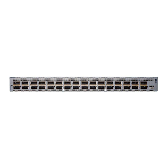
 Lists the cables required for installation of the device.
Appendix C Front Panel This appendix displays the front panel of all switches covered by this guide. Note: All devices are designed to fit into a 19” rack. Figure C-1: DCS-7060DX5-64 and DCS-7060DX5-64E 1 Port numbers 3 Fan status LED 5 Power supply 2 status LED 2 System status LED 4 Power supply 1 status LED...
Page 46
Front Panel Figure C-4: DCS-7060DX5-64S 1 Port number and Port 4 Console (serial) port 7 Power supply 1 status LED Status LED 2 Ethernet management 5 System status LED 8 Power supply 2 status LED port 3 USB port 6 Fan status LED...
Appendix D Rear Panel All switches covered by this guide use one of the rear panels shown below. Depending on the installed power supply module, the appearance could be different from those shown. Some of the PSUs have a velcro strap for cable management.
All slots must be filled or covered with a blank for operation (even though power supply or fans may not be functional). • Before you begin, refer to the Arista Networks document Safety Information and Translated Safety Warnings available at: https://www.arista.com/en/support/product-documentation. Note: Descriptions for the removal and replacement of power supplies and fans are for a representative power supply or fan.
3. Push the power supply release lever and remove the power supply Figure 38: Removing and Installing Power Supply. Figure E-1: Removing and Installing Power Supply 1 Release lever 2 Remove PSU E.2.2 Installing a Power Supply You must make space for installing the power supply by removing an existing one Removing a Power Supply.
Maintenance and Field Replacement 2. Push the fan module release lever and slide the fan module out of the switch. Figure E-2: Removing Fan Module 1 Release lever E.3.2 Installing a Fan Module You must make space for installing the fan module by removing an existing one. 1.
Appendix F Regulatory Model Numbers This appendix lists the Regulatory Model Numbers (RMNs), where applicable, for the product models for the switches described in this document. Table 14: Regulatory Model Numbers and Product Numbers Regulatory Model Number (RMN) Product Number(s) AN1789 DCS-7060DX5-64E AN1768...
Appendix G Taiwan RoHS Information This appendix provides Taiwan RoHS information for switches covered by this guide. For Taiwan BSMI RoHS Table, go to https://www.arista.com/assets/data/pdf/AristaBSMIRoHS.pdf.
Need help?
Do you have a question about the 7060X5 Series and is the answer not in the manual?
Questions and answers