
Subscribe to Our Youtube Channel
Related Manuals for Arista 7500 Series


Summary of Contents for Arista 7500 Series
- Page 1 Quick Start Guide 7500 Series Modular Data Center Switches DCS-7508 / 7508E DCS-7504 / 7504E Arista Networks www.arista.com PDOC-00015-07...
- Page 2 © Copyright 2015 Arista Networks, Inc. The information contained herein is subject to change without notice. Arista Networks and the Arista logo are trademarks of Arista Networks, Inc in the United States and other countries. Other product or service names...
-
Page 3: Chapter 1 Overview
Important! Ultimate disposal of this product should be handled in accordance with all national laws and regulations. Safety Information Refer to the Arista Networks document Safety Information and Translated Safety Warnings available at: http://www.arista.com/support/docs/eos 7500 Series Modular Switch Quick Start Guide... -
Page 4: Obtaining Technical Assistance
Chapter 1: Overview Obtaining Technical Assistance Any customer, partner, reseller or distributor holding a valid Arista Service Contract can obtain technical support in any of the following ways: • Email: support@arista.com. This is the easiest way to create a new service request. -
Page 5: Chapter 2 Preparation
— AC power cords can reach from the AC power outlet to the connectors on the front panel. Important! Disconnecting power to all input sockets is required to completely power off the unit. 7500 Series Modular Switch Quick Start Guide PDOC-00015-07... -
Page 6: Tools Required For Installation
Minimize handling of assemblies and components. • Keep replacement parts in their original static-free packaging. • Remove all plastic, foam, vinyl, paper, and other static-generating materials from the work area. • Use tools that do not create ESD. Arista Networks Copyright 2015... -
Page 7: Chapter 3 Rack Mounting The Switch
Position the flanges that attach to the rack posts toward the rear of the chassis. Step 2 Attach both center-mount brackets to the chassis. Each bracket requires ten M4x8 panhead Phillips screws. Figure 2: Attaching the Center-mount Brackets 7500 Series Modular Switch Quick Start Guide PDOC-00015-07... -
Page 8: Inserting The Switch Into The Rack
Figure 4: Attaching Flanges to the Rack Post After completing the two-post installation, proceed to Chapter Four-Post Rack Mount The switch is mounted onto a four-post rack by assembling a shelf into the rack, then placing the switch on the shelf. Arista Networks Copyright 2015... -
Page 9: Assembling The Shelf
The back bracket is not required on threaded racks. Step 4 Adjust the left shelf by sliding its components to fit between the front left and front rear rack posts, as shown in Figure 7500 Series Modular Switch Quick Start Guide PDOC-00015-07... - Page 10 Press down firmly on the shelf to ensure it is seated securely on the rack posts.. Step 6 Install the right shelf on the right front and right rear rack posts by repeating step 4 and step 5 to obtain the rack configuration shown in Figure Arista Networks Copyright 2015...
- Page 11 Chapter 3: Rack Mounting the Switch Figure 8: Seating the Left Shelf Figure 9: Both Switch Shelves Installed 7500 Series Modular Switch Quick Start Guide PDOC-00015-07...
- Page 12 Step 3 Secure the chassis by tightening the four thumbscrews on the front flanges into the rack posts (Figure 11). Figure 11: Inserting the Switch onto the Rack Shelf After completing the Four-Post Installation, proceed to Chapter Arista Networks Copyright 2015...
-
Page 13: Chapter 4 Cabling The Modular Switch
DCS-7504 / 7504E requires the connection of one power supply to an active live circuit. Connecting power to all four power supplies protects against up to two failed power supplies and can provide grid-level redundancy. Energizing any power supply causes all power supply fans to function. 7500 Series Modular Switch Quick Start Guide PDOC-00015-07... -
Page 14: Connecting Supervisor Cables
Important! This unit requires overcurrent protection. Connecting Supervisor Cables Supervisor modules contain console, management, and USB ports. Figure 15 displays port locations on supervisors provided with 7508 / 7504 switches. Figure 15: Supervisor Ports: 7508 / 7504 Switches Arista Networks Copyright 2015... -
Page 15: Connecting Linecard Modules And Cables
Connect cables as required to linecard module ports or fixed MPO ports. Supervisor and linecard module ejectors on the front of the chassis assist with cable management. Caution Excessive bending can damage interface cables, especially optical cables. 7500 Series Modular Switch Quick Start Guide PDOC-00015-07... -
Page 16: Chapter 5 Configuring The Modular Switch
Chapter 5: Configuring the Modular Switch Chapter 5 Configuring the Modular Switch Arista switches ship from the factory in Zero Touch Provisioning (ZTP) mode. ZTP configures the switch without user intervention by downloading a startup configuration file or a boot script from a location specified by a DHCP server. -
Page 17: Appendix A Status Indicators
Table 4: Supervisor Status Summary Screen LED States: 7508 / 7504 LED State Status Gray Module not present or improperly inserted. Green Module operating normally. Module has failed. 7500 Series Modular Switch Quick Start Guide PDOC-00015-07... - Page 18 All powered modules are operating normally. Fabric Module At least one module has failed. Amber At least one fan is missing or has failed. Fan Modules Green All modules are operating normally. There are insufficient functional fans installed in the switch. Arista Networks Copyright 2015...
-
Page 19: Linecard Module Indicators
10G ports, each port is assigned to an LED within the set. Table 8 interprets the port LED states. Table 8: Linecard Port LED States LED State Status Port link is down. Green Port link is up. Yellow Port is disabled in software. 7500 Series Modular Switch Quick Start Guide PDOC-00015-07... -
Page 20: Fan And Fabric Status Indicators
Power Supply Status LED. Table 10: Power Supply Status OK LED Fault LED Status Green Power Supply operating normally. Yellow No AC power on this supply. Module has failed. No AC power on any supply. Arista Networks Copyright 2015... -
Page 21: Appendix B Parts List
Two-Post Rack Mount Parts Table 11: Two-Post Rack Mount Parts Quantity Description Center-mount brackets. M4x8 panhead Phillips screws. Figure 23: Two-Post Rack Mount Parts 7500 Series Modular Switch Quick Start Guide PDOC-00015-07... -
Page 22: Four-Post Rack Mount Parts
Table 12: Four-Post Rack Mount Parts Quantity Description Front brackets. Shelf supports. Back brackets. Left shelf. Right shelf. M6X16 panhead Phillips screws. M6 Cage Hex Nuts. M6 Cage Nut Square Hole Racks. Figure 24: Four-Post Rack Mount Parts Arista Networks Copyright 2015... -
Page 23: Parts Used In All Rack Mount Configurations
Quantity Description power cables: 14 AWG, C19-C20, 2 meters. RJ-45 Patch Panel Cables, 2 meters. RJ-45 to DB9 Adapter Cable, 2 meters. Warning! All provided power cables are for use only with Arista products. 警告 すべての電源コードは提供する製品で使用するためだけを目的としている。 電源コードの他の製品での使用の禁止 Arista が提供するすべての電源コードは、Arista の製品でのみ使用してください。... -
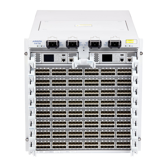
Page 24: Appendix C Front Panels
Appendix C: Front Panels Appendix C Front Panels This appendix displays the front panel of all switches covered by this guide. DCS-7508 Front Panel (fully populated) DCS-7504 Front Panel (fully populated) Arista Networks Copyright 2015... - Page 25 Appendix C: Front Panels DCS-7508E Front Panel (fully populated) DCS-7504E Front Panel (fully populated) 7500 Series Modular Switch Quick Start Guide PDOC-00015-07...
-
Page 26: Appendix D Rear Panel
Appendix D: Rear Panel Appendix D Rear Panel This appendix displays the rear panel of all switches covered by this guide. DCS-7508 Rear Panel DCS-7504 Rear Panel Arista Networks Copyright 2015... - Page 27 Appendix D: Rear Panel DCS-7508E Rear Panel DCS-7504E Rear Panel 7500 Series Modular Switch Quick Start Guide PDOC-00015-07...
-
Page 28: Appendix E Linecards
Appendix E: Linecards Appendix E Linecards This appendix displays the linecards supported by modular switches covered by this guide. DCS-7548S-LC DCS-7500E-36Q-LC DCS-7500E-72S-LC DCS-7500E-48S-LC Arista Networks Copyright 2015... - Page 29 Appendix E: Linecards DCS-7500E-12CM-LC Status LED MXP Port LEDs DCS-7500E-6C2-LC DCS-7500E-12CQ-LC 7500 Series Modular Switch Quick Start Guide PDOC-00015-07...
- Page 30 Appendix E: Linecards Arista Networks Copyright 2015...
Need help?
Do you have a question about the 7500 Series and is the answer not in the manual?
Questions and answers