Advertisement
Quick Links
INSTALLATION MANUAL
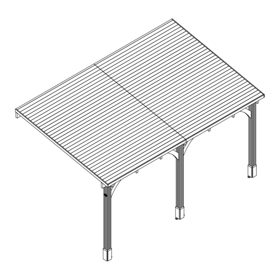
Leviathan Canopy Gazebo 3.0m x 5.0m
Please note:
1.
If you have bought shingles, please use our shingle installation instructions.
2.
Fixings are supplied with Gazebo (except those required to secure bracket to base and to secure the
gazebo to your wall).
Manufacturer:
Dunster House Ltd.
Caxton Road
Bedford
Bedfordshire
England
MK41 0LF
P5-3050CANGAZ
Unique Product Reference Number:
__________________________________
Customer Service Department:
cs@dunsterhouse.co.uk
www.dunsterhouse.co.uk
Advertisement

Subscribe to Our Youtube Channel
Related Manuals for Dunster House Leviathan P5-3050CANGAZ


Summary of Contents for Dunster House Leviathan P5-3050CANGAZ
- Page 1 If you have bought shingles, please use our shingle installation instructions. Fixings are supplied with Gazebo (except those required to secure bracket to base and to secure the gazebo to your wall). Unique Product Reference Number: Manufacturer: Dunster House Ltd. Caxton Road __________________________________ Bedford Customer Service Department: Bedfordshire cs@dunsterhouse.co.uk...
- Page 2 In the unlikely event that you need to contact us, please do so in writing to: Email: cs@dunsterhouse.co.uk Post: Dunster House Ltd, Caxton Road, Elms Farm Industrial Estate, Bedford, MK41 0LF, England. Our Customer Service department is open 9 a.m. to 5 p.m. Monday to Friday. Please include your Sales Order (SO) number or post code in any correspondence with Customer Service to enable them to locate your file.
- Page 3 Page 3 Components required for Leviathan Canopy Gazebo 3.0m x 5.0m ROOF BOARD LNG_mm THK_mm PART NUMBER DESCRIPTION THK_mm WIDTH_mm LNG_mm F.2575 Roof Board 2575 ROOF BOARD LNG_mm THK_mm PART NUMBER DESCRIPTION THK_mm WIDTH_mm LNG_mm F.402575 Roof Board 2575 POST THK_mm LNG_mm PART NUMBER...
- Page 4 Page 4 Components required for Leviathan Canopy Gazebo 3.0m x 5.0m FASCIA LNG_mm THK_mm PART NUMBER DESCRIPTION THK_mm WIDTH_mm LNG_mm 19x70x3140.A Fascia 3140 POST TRIM THK_mm WIDTH_mm PART NUMBER DESCRIPTION THK_mm WIDTH_mm LNG_mm 20x120x300.A Post Trim ROOF TRIM LNG_mm THK_mm PART NUMBER DESCRIPTION THK_mm...
- Page 5 Page 5 Components required for Leviathan Canopy Gazebo 3.0m x 5.0m RAFTER LNG_mm THK_mm PART NUMBER DESCRIPTION THK_mm WIDTH_mm LNG_mm 45x140x3135.A Rafter 3135 BRACE LNG_mm THK_mm PART NUMBER DESCRIPTION THK_mm WIDTH_mm LNG_mm 45x140x630.A Brace FIXINGS PARTS LIST PART NUMBER DESCRIPTION Nail 40mm Shank Nails SCREW 100 mm...
- Page 6 Assembly Steps for Leviathan Canopy Gazebo 3.0m x 5.0m Page 6 ** Avoid splitting timber parts by pre-drilling all screw holes ** Step 1: • Once the location of your building has been established, position and fix 2x 45x140x2575 to the wall COMPONENTS REQUIRED using screws and suitable rawlplugs (not supplied) in the position shown from ground level.
- Page 7 Assembly Steps for Leviathan Canopy Gazebo 3.0m x 5.0m Page 7 ** Avoid splitting timber parts by pre-drilling all screw holes ** Step 3: • Position and fix 3x 45x140x3135.A using 1x H2.5 Bracket, 10x 35mm screw and 2x 100mm screw COMPONENTS REQUIRED per rafter as shown below.
- Page 8 Assembly Steps for Leviathan Canopy Gazebo 3.0m x 5.0m Page 8 ** Avoid splitting timber parts by pre-drilling all screw holes ** Step 4: • Fix 4x 45x140x630.A using 2x M10 120mm hex head screw and 2x M10 washer per brace. COMPONENTS REQUIRED PART NUMBER •...
- Page 9 Assembly Steps for Leviathan Canopy Gazebo 3.0m x 5.0m Page 9 ** Avoid splitting timber parts by pre-drilling all screw holes ** Step 6: • Fix 2x 35x35x3100 to the roof boards, using 10x 35mm screw per trim as shown. COMPONENTS REQUIRED PART NUMBER 19x70x2575...
- Page 10 Assembly Steps for Leviathan Canopy Gazebo 3.0m x 5.0m Page 10 ** Avoid splitting timber parts by pre-drilling all screw holes ** Step 7: • Fix 4x 20x120x300.A to each post, using 2x 35mm screw per post trim. COMPONENTS REQUIRED PART NUMBER •...
- Page 11 Felt Instructions Page 11 Please note: These images are used for reference only and may differ from your structure in size and/or orientation. • Place and fix the first row of felt over the top • Fully cover the roof boards with the plastic of the waterproof membrane, overhanging the waterproof membrane, overhanging the roof roof by a minimum of 40-50mm and spacing...
- Page 12 Shingle Instructions Page 12 Please note: These images are used for reference only and may differ from your structure in size and/or orientation. • Place and fix the first row of shingles over the • Fully cover the roof boards with the plastic top of the waterproof membrane with the slots waterproof membrane, overhanging the roof running upwards, overhanging the roof by...
- Page 13 Guttering Installation Page 13 Fig.A • Screw the running outlet to the fascia, ensuring the Running outlet downpipe will be in line with your post (Fig.A). • Fix the support brackets to the fascia using two screws per bracket and ensuring spacing of 400-600mm between each support bracket (Fig.B).
- Page 14 INSTALLATION MANUAL Additional Wall Panels IMPORTANT INFORMATION Please remove component 45x140x630.A (Brace) and internal 20x120x300.A (Post Trim) if components CP1 and or CP8 are being installed. Please note: 1. These instructions will enable you to assemble additional wall panels to your building. The configuration of the panels shown on the illustrations may vary from the product you have purchased.
- Page 15 Additional Wall Panels- Pack may contain Page 15 Panel CP1 Panel CP2 Pressure Treated Pressure Treated Panel CP8 Pressure Treated...
- Page 16 Additional Wall Panels- Pack may contain Page 16 15x70x2120 Full Wall Panel Trim 2120 15x70x1065 1065 Half Wall Panel Trim (Cut from full height trim) 15x70x1035 1035 Glass Wall Panel Trim (Cut from full height trim) 20x100x908 Glass Wall Panel Sill 15x70x1085 Half Wall Panel Trim 1085...
- Page 17 Assembly Steps for Wall Options Page 17 Full height wall panels assembly ** Quantity of components will vary, Panel CP1 M10 Shield Anchors depending on your purchase. 60mm Screws M10x28 Washers M10x110 Bolts Step 1. • Position the Panel CP1 between the Posts as shown in the diagram below. •...
- Page 18 Assembly Steps for Wall Options Page 18 Full height wall panels assembly 35mm Screws 15x70x2120 Trim Step 2. • Fix 15x70x2120 Trims using 8x 35mm screws per trim on the outside of the wall panels. • Fix 15x70x2120 Trims using 8x 35mm screws per trim on the inside of the wall panels. •...
- Page 19 Assembly Steps for Wall Options Page 19 Half height wall panels assembly ** Quantity of components will vary, Panel CP2 M10 Shield Anchors depending on your purchase. M10x28 Washers 60mm Screws M10x110 Bolts Step 1. • Position the Panel CP2 between the Posts as shown in the diagram below. Join 2x Panel CP2 using 6x 60mm screws.
- Page 20 Assembly Steps for Wall Options Page 20 Half height wall panels assembly 20x100x908 35mm Screws 15x70x1065 15x70x1085 Step 2. • Position 20x100x908 Sills on top of Panels CP2 so that they are flush with the panel frame from inside the gazebo.
- Page 21 Assembly Steps for Wall Options Page 21 Window panels assembly Panel CP8 60mm Screws **Assemble half height wall panels according to 35mm Screws the instructions given on the previous pages. 15x70x1035 • Remove the beading trims from one side of Panel CP8 frames. Step 1.
- Page 22 Assembly Steps for Wall Options Page 22 40mm Pin Nail 4x825x960 TGLASS 19x25x840 19x25x915 Step 1: Place silicone around the edge of the frame. Silicone Please note: The glass is a smaller size compared to panel frame to compensate for timbers Silicone Silicone contracting, swelling and glass not being...
Need help?
Do you have a question about the Leviathan P5-3050CANGAZ and is the answer not in the manual?
Questions and answers