
Related Manuals for Avalue Technology EMX-RPLP


Summary of Contents for Avalue Technology EMX-RPLP
- Page 1 EMX-RPLP 13th Gen Intel® Core™ SoC & Celeron Processor Mini ITX Motherboard User’s Manual Ed – 15 January 2024 Part No. E2047EMRP00R...
- Page 2 Disclaimer Avalue Technology Inc. reserves the right to make changes, without notice, to any product, including circuits and/or software described or contained in this manual in order to improve design and/or performance. Avalue Technology assumes no responsibility or liability for the...
- Page 3 Applications that are described in this manual are for illustration purposes only. Avalue Technology Inc. makes no representation or warranty that such application will be suitable for the specified use without further testing or modification.
- Page 4 A product returned without proof of the purchase date is not eligible for warranty service. Write the RMA number visibly on the outside of the package and ship it prepaid to your dealer. 4 EMX-RPLP User’s Manual...
-
Page 5: Table Of Contents
2.3.20 USB connector 4 (JUSB4) ......................30 2.3.21 Speaker connector (SPK1) ......................31 2.3.22 Battery connector (BT1) ........................ 31 2.3.23 Audio connector (JFAUD1) ......................32 2.3.24 JEC1 connector (JEC1) ......................... 32 2.3.25 ESPI1 connector (JESPI1) ......................33 EMX-RPLP User’s Manual... - Page 6 S5 RTC Wake Settings ......................51 3.6.2.10 Serial Port Console Redirection .................... 51 3.6.2.10.1 Legacy Console Redirection Settings ................... 52 3.6.2.11 USB Configuration ......................... 52 3.6.2.12 Network Stack Configuration ....................53 3.6.2.13 NVMe Configuration ......................54 3.6.3 Chipset ............................54 6 EMX-RPLP User’s Manual...
- Page 7 Install VGA Driver ....................73 Install ME Driver ...................... 74 Install Audio Driver (For Realtek ALC897 and ALC888S HD Audio) ....... 75 Install LAN Driver ....................76 Install Serial IO Driver ..................... 77 5. Mechanical Drawing ....................78 EMX-RPLP User’s Manual...
-
Page 8: Getting Started
1.2 Packing List Before you begin installing your single board, please make sure that the following materials have been shipped: 1 x EMX-RPLP motherboard 1 x SATA cable 1 x SATA power cable ... -
Page 9: Document Amendment History
User’s Manual 1.3 Document Amendment History Revision Date Comment January 2024 Avalue Initial Release EMX-RPLP User’s Manual... -
Page 10: Manual Objectives
We strongly recommend that you study this manual carefully before attempting to set up EMX-RPLP or change the standard configurations. Whilst all the necessary information is available in this manual we would recommend that unless you are confident, you contact your supplier for guidance. -
Page 11: System Specifications
Support Line-out & Mic-in & Front audio pin-header DC in +12V~24V Product Specification Onboard Raptor Lake-P 13th Intel® Core™ SoC i7/i5/i3/Celeron Processor (TDP: 15~45W) H-Series: 25~45W, P-Series: 20~28W, U-Series: 12~15W BIOS AMI uEFI BIOS, 256Mbit SPI Flash ROM EMX-RPLP User’s Manual 11... - Page 12 2 x DP++ (Thin Mini ITX) 2 x DP++, 2 x DP (Full height Mini ITX) DC Input Mini Din 4-pin DC in Jack Onboard I/O 2 x 2 x 3 pin, pitch 2.00mm connector jumper for RS-422/485 12 EMX-RPLP User’s Manual...
- Page 13 DP1~DP4 (DP2.1): Max: 8192 x 4320@60 Hz 2 x DP++ (DP1+DP2): 1920 x 1080@60 Hz Spec. & LVDS: 1920 x 1080 Dual channel 18/24-bits LVDS (Chrontel CH7511B eDP to Resolution LVDS) eDP 4096 x 2304@60 Hz EMX-RPLP User’s Manual 13...
- Page 14 -40~ +75°C Operating 40°C @ 95% Relative Humidity, Non-condensing Humidity Size (L x W) 6.7" x 6.7" (170mm x 170mm) Weight 0.88lbs (0.4kg) Win11 64bit, Win10 64bit. OS Information Linux Power DC in +12V ~ +24V 14 EMX-RPLP User’s Manual...
- Page 15 User’s Manual Requirement Single power ATX Support S0, S3, S4, S5 ACPI ACPI 5.0 Compliant Note: Specifications are subject to change without notice. EMX-RPLP User’s Manual 15...
-
Page 16: Architecture Overview-Block Diagram
EMX-RPLP User’s Manual 1.6 Architecture Overview—Block Diagram The following block diagram shows the architecture and main components of EMX-RPLP. 16 EMX-RPLP User’s Manual... -
Page 17: Hardware Configuration
User’s Manual 2. Hardware Configuration EMX-RPLP User’s Manual 17... -
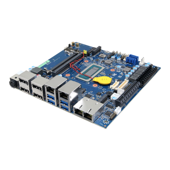
Page 18: Product Overview
EMX-RPLP User’s Manual 2.1 Product Overview 18 EMX-RPLP User’s Manual... -
Page 19: Jumper And Connector List
JFPT1/2 Miscellaneous setting connector 1/2 5 x 2 header, pitch 2.54mm SODIMM1/2 206-pin DDR4 SO-DIMM socket 6 x 2 header, pitch 2.00mm JFAUD1 Front Audio connector 5 x 1 wafer, pitch 2.00mm JBKL1/2 LCD Inverter connector EMX-RPLP User’s Manual 19... - Page 20 SATA Power connector 1 EXT_SIM SIM card slot Can Only use either one slot, not both at the same time. INT_SIM SIM card slot CPU fan connector 4 x 1 wafer, pitch 2.54mm CPU_FAN1 PCle connector PCIE1 20 EMX-RPLP User’s Manual...
-
Page 21: Setting Jumpers & Connectors
User’s Manual 2.3 Setting Jumpers & Connectors 2.3.1 Serial port 1/2 pin9 signal select (JRI1/JRI2) Ring* JRI1 JRI2 +12V * Default 2.3.2 LVDS Back Light power selection (JSBKL1) PWM Mode* DC Mode * Default EMX-RPLP User’s Manual 21... -
Page 22: At/Atx Power Mode Select (Jsatx1)
EMX-RPLP User’s Manual 2.3.3 AT/ATX Power Mode Select (JSATX1) ATX* * Default 2.3.4 M2KB2 Voltage setting (JP1) +3.8V +3.3V* * Default 22 EMX-RPLP User’s Manual... -
Page 23: Clear Cmos (Jrtc1)
User’s Manual 2.3.5 Clear CMOS (JRTC1) Protect* Clear CMOS * Default 2.3.6 LCD Inverter connector (JBKL1) Signal +12V_INV LVDS_BKLT_EN LVDS_BKLTCTL EMX-RPLP User’s Manual 23... -
Page 24: Lcd Inverter Connector (Jbkl2)
LVDS_DATA0_N 12 11 LVDS_DATA1_N LVDS_DATA2_P 16 15 LVDS_DATA3_P LVDS_DATA2_N 18 17 LVDS_DATA3_N LVDS_DATA4_P 22 21 LVDS_DATA5_P LVDS_DATA4_N 24 23 LVDS_DATA5_N LVDS_DATA6_P 28 27 LVDS_DATA7_P LVDS_DATA6_N 30 29 LVDS_DATA7_N LVDS_CLK1_P LVDS_CLK2_P LVDS_ CLK1_N LVDS_ CLK2_N +V12S_LVDS +V12S_LVDS 24 EMX-RPLP User’s Manual... -
Page 25: Edp_Panel Connector (Edp1)
PIN PIN Signal EDP_PANEL_TXN3 EDP_PANEL_TXN0 EDP_PANEL_TXP3 EDP_PANEL_TXP0 EDP_PANEL_TXN1 EDP_PANEL_AUXN 12 EDP_PANEL_TXP1 EDP_PANEL_AUXP 14 EDP_PANEL_TXN2 EDP_PANEL_HPD EDP_PANEL_TXP2 +V35_EDP +V35_EDP 2.3.10 General purpose I/O connector (JDIO1) Signal PIN PIN Signal SMB_SCL_ SMB_SDA_ S0_3P3EXT S0_3P3EXT (Max current = 0.5A) EMX-RPLP User’s Manual 25... -
Page 26: Serial Port1 Connector (Jcom1)
EMX-RPLP User’s Manual 2.3.11 Serial port1 connector (JCOM1) Signal PIN PIN Signal COM_DCD#_1 COM_RXD_1 COM_TXD_1 COM_DTR#_1 COM_DSR#_1 COM_RTS#_1 COM_CTS#_1 COM_RI#_1 2.3.12 Serial port2 connector (JCOM2) Signal PIN PIN Signal COM_DCD#_2 COM_RXD_2 COM_TXD_2 COM_DTR#_2 COM_DSR#_2 COM_RTS#_2 COM_CTS#_2 COM_RI#_2 26 EMX-RPLP User’s Manual... -
Page 27: Serial Port3 Connector (Jcom3)
User’s Manual 2.3.13 Serial port3 connector (JCOM3) Signal PIN PIN Signal COM_DCD#_3 COM_RXD_3 COM_TXD_3 COM_DTR#_3 COM_DSR#_3 COM_RTS#_3 COM_CTS#_3 COM_RI#_3 2.3.14 Serial port4 connector (JCOM4) Signal PIN PIN Signal COM_DCD#_4 COM_RXD_4 COM_TXD_4 COM_DTR#_4 COM_DSR#_4 COM_RTS#_4 COM_CTS#_4 COM_RI#_4 EMX-RPLP User’s Manual 27... -
Page 28: Serial Port 1 Rs485/422 Mode Connector (Jrs485_1)
2.3.15 Serial Port 1 RS485/422 Mode connector (JRS485_1) Signal PIN PIN Signal 485_422TX1- 485_422TX1+ 485RX1+ 485RX1- (Max current = 0.5A) 2.3.16 Serial Port 2 RS485/422 Mode connector (JRS485_2) Signal PIN PIN Signal 485_422TX2- 485_422TX2+ 485RX2+ 485RX2- 28 EMX-RPLP User’s Manual... -
Page 29: Sata Power Connector 1 (Spwr1)
User’s Manual 2.3.17 SATA Power connector 1 (SPWR1) Signal +5V_SATA +12V_SATA 2.3.18 Power connector (PWR1) Signal Signal +VIN +VIN EMX-RPLP User’s Manual 29... -
Page 30: Usb Connector 3 (Jusb3)
EMX-RPLP User’s Manual 2.3.19 USB connector 3 (JUSB3) Signal Signal +V5A_USB56 +V5A_USB56 USB_DN5 USB_DN6 USB_DP5 USB_DP6 2.3.20 USB connector 4 (JUSB4) Signal Signal +V5A_USB78 +V5A_USB78 USB_DN7 USB2_ DN8 USB_DP7 USB2_ DP8 30 EMX-RPLP User’s Manual... -
Page 31: Speaker Connector (Spk1)
User’s Manual 2.3.21 Speaker connector (SPK1) Signal SPK_L+ SPK_L- SPK_R+ SPK_R- 2.3.22 Battery connector (BT1) Signal +RTCBAT EMX-RPLP User’s Manual 31... -
Page 32: Audio Connector (Jfaud1)
EMX-RPLP User’s Manual 2.3.23 Audio connector (JFAUD1) Signal PIN PIN Signal LINEOUT_R LINEOUT_L GND_AUD GND_AUD LINEIN_R LINEIN_L MICIN_R MICIN_L LINEOUT1_JD LINE1-JD MIC1_JD GND_AUD 2.3.24 JEC1 connector (JEC1) Signal EC_SMDAT_DEBUG EC_SMCLK_DEBUG 32 EMX-RPLP User’s Manual... -
Page 33: Espi1 Connector (Jespi1)
User’s Manual 2.3.25 ESPI1 connector (JESPI1) Signal PIN PIN Signal ESPI_ALER1# ESPI_RST# ESPI_CS1# ESPI_CLK_80P ESPI_IO3_80P ESPI_CS# ESPI_IO2_80P PLT_BUF_RST# ESPI_IO1_80P +3.3V ESPI_IO0_80P 2.3.26 SPI connector (JSPI) Signal PIN PIN Signal BIOS_WP# BIOS_HOLD# SPI0_BIOS_MOSI SPI0_BIOS_MISO SPI0_BIOS_CLK SPI0_CS0# +V3.3A_1.8A_SPI EMX-RPLP User’s Manual 33... -
Page 34: Miscellaneous Setting Connector 1 (Jfpt1)
EMX-RPLP User’s Manual 2.3.27 Miscellaneous setting connector 1 (JFPT1) Signal PIN PIN Signal EXT_PWRBNT# EXT_SYSRST# PWR_LED- HD_LED- PWR_LED+ HD_LED+ 2.3.28 Miscellaneous setting connector 2 (JFPT2) Signal PIN PIN Signal Speaker- BLK_DN BLK_UP BLK_VR(10K) Speaker+ 34 EMX-RPLP User’s Manual... -
Page 35: Cpu Fan Connector (Cpu_Fan1)
User’s Manual 2.3.29 CPU fan connector (CPU_FAN1) Signal FAN_PWM0 CPU_FANIN +12V 2.3.30 Power connector (DCIN1) Signal Signal +VIN_12-24V +VIN_12-24V Vin = 12~24V Note: EMX-RPLP User’s Manual 35... -
Page 36: Bios Setup
EMX-RPLP User’s Manual 3.BIOS Setup 36 EMX-RPLP User’s Manual... -
Page 37: Introduction
If you do not press the keys at the correct time and the system does not boot, an error message will be displayed and you will again be asked to. Press F1 to Continue, DEL to enter SETUP EMX-RPLP User’s Manual 37... -
Page 38: Using Setup
Note: Some of the navigation keys differ from one screen to another. To Display a Sub Menu Use the arrow keys to move the cursor to the sub menu you want. Then press <Enter>. A “” pointer marks all sub menus. 38 EMX-RPLP User’s Manual... -
Page 39: Getting Help
BIOS Vendor and your systems manufacturer to provide the absolute maximum performance and reliability. Even a seemingly small change to the chipset setup has the potential for causing you to use the override. EMX-RPLP User’s Manual 39... -
Page 40: Bios Setup
<Enter> to accept and enter the sub-menu. 3.6.1 Main Menu This section allows you to record some basic hardware configurations in your computer and set the system clock. 40 EMX-RPLP User’s Manual... -
Page 41: System Language
Visit the Avalue website (www.avalue.com.tw) to download the latest product and BIOS information. 3.6.2 Advanced Menu This section allows you to configure your CPU and other system devices for basic operation through the following sub-menus. EMX-RPLP User’s Manual 41... -
Page 42: Connectivity Configuration
Disable Integrated enabled by default. Otherwise Integrated CNVi Mode Auto Detection[Default] solution (CNVi) will be enabled; [Disable Integrated] disables Integrated Solution. NOTE: When CNVi is present, the GPIO pins that are used for radio 3.6.2.2 CPU Configuration 42 EMX-RPLP User’s Manual... -
Page 43: Efficient-Core Information
Number of E-cores to enable in each processor package. Active Efficient-cores 15/14/13/12/11/10/ Note: Number of Cores and E-cores are looked at 9/8/7/6/5/4/3/2/1/0 together. When both are {0,0}, Pcode will enable all cores. 3.6.2.2.1 Efficient-core Information 3.6.2.2.2 Performance-core Information EMX-RPLP User’s Manual 43... -
Page 44: Power & Performance
Enable/Disable Intel(R) Speed Shift Technology Intel(R) Speed Shift Disabled support. Enabling will expose the CPPC v2 interface Technology Enabled[Default], to allow for hardware controlled P-states. Enable/Disable processor Turbo Mode (requires Disabled Turbo Mode Enabled[Default], EMTTM enabled too). AUTO means enabled. 44 EMX-RPLP User’s Manual... -
Page 45: Pch-Fw Configuration
Enhanced C-states Enabled[Default], to minimum speed when all cores enter C-State. 3.6.2.4 PCH-FW Configuration Item Options Description Disabled When Disabled ME will be put into ME Temporarily ME State Enabled[Default], Disabled Mode. 3.6.2.4.1 Firmware Update Configuration EMX-RPLP User’s Manual 45... -
Page 46: Trusted Computing
3.6.2.5 Trusted Computing Item Options Description Enables or Disables BIOS support for security device. Security Device Disabled O.S. will not show Security Device. TCG EFI protocol Support Enabled[Default], and INT1A interface will not be available. 3.6.2.6 ACPI Settings 46 EMX-RPLP User’s Manual... -
Page 47: Super Io Configuration
Set Parameters of Serial Port 1 (COMA). Serial Port 2 Configuration Set Parameters of Serial Port 2 (COMB). Serial Port 3 Configuration Set Parameters of Serial Port 3 (COMC). Serial Port 4 Configuration Set Parameters of Serial Port 4 (COMD). EMX-RPLP User’s Manual 47... -
Page 48: Serial Port 1 Configuration
Enable or Disable Serial Port (COM). Enabled[Default], UART 232[Default], UART 232 422 485 UART 422, Change the Serial Port as RS232/422/485. UART 485 3.6.2.7.2 Serial Port 2 Configuration Item Option Description Disabled Serial Port Enable or Disable Serial Port (COM). Enabled[Default], 48 EMX-RPLP User’s Manual... -
Page 49: Serial Port 3 Configuration
UART 485 3.6.2.7.3 Serial Port 3 Configuration Item Option Description Disabled Serial Port Enable or Disable Serial Port (COM). Enabled[Default], Auto[Default], IO=3E8h;IRQ=7; IO=3E8h;IRQ=3,4,5,6,7,9,10,11 Select an optimal settings for Super IO Change Settings IO=2E8h;IRQ=3,4,5,6,7,9,10,11 Device IO=2F0h;IRQ=3,4,5,6,7,9,10,11 IO=2E0h;IRQ=3,4,5,6,7,9,10,11 EMX-RPLP User’s Manual 49... -
Page 50: Serial Port 4 Configuration
3.6.2.7.4 Serial Port 4 Configuration Item Option Description Disabled Serial Port Enable or Disable Serial Port (COM). Enabled[Default], Auto[Default], IO=3E8h;IRQ=7; IO=3E8h;IRQ=3,4,5,6,7,9,10,11 Select an optimal settings for Super IO Change Settings IO=2E8h;IRQ=3,4,5,6,7,9,10,11 Device IO=2F0h;IRQ=3,4,5,6,7,9,10,11 IO=2E0h;IRQ=3,4,5,6,7,9,10,11 3.6.2.8 EC 5782 HW monitor 50 EMX-RPLP User’s Manual... -
Page 51: S5 Rtc Wake Settings
Enable or disable System wake on alarm event. Select Disabled[Default], FixedTime, system will wake on the hr::min::sec specified. Wake system from S5 Fixed Time Select DynamicTime, System will wake on the current Dynamic Time time + Increase minutes(s). 3.6.2.10 Serial Port Console Redirection EMX-RPLP User’s Manual 51... -
Page 52: Legacy Console Redirection Settings
Item Options Description Select a COM port to display redirection of Legacy Redirection COM Port COM0 OS and Legacy OPROM Messages 3.6.2.11 USB Configuration The USB Configuration menu helps read USB information and configures USB settings. 52 EMX-RPLP User’s Manual... -
Page 53: Network Stack Configuration
Optical drives are emulated as ‘CDROM’, drives with no Hard Disk media will be emulated according to a drive type. CD-ROM 3.6.2.12 Network Stack Configuration Item Options Description Disabled[Default] Network Stack Enable/Disable UEFI Network Stack. Enabled EMX-RPLP User’s Manual 53... -
Page 54: Nvme Configuration
EMX-RPLP User’s Manual 3.6.2.13 NVMe Configuration 3.6.3 Chipset 54 EMX-RPLP User’s Manual... -
Page 55: System Agent (Sa) Configuration
User’s Manual 3.6.3.1 System Agent (SA) Configuration Item Option Description Disabled[Default] VT-d VT-d capability. Enabled 3.6.3.1.1 Memory Configuration EMX-RPLP User’s Manual 55... -
Page 56: Graphics Configuration
Select which of IGFX/PEG/PCI Graphics Primary Display PEG Slot device should be Primary Display Or select PCH PCI HG for Hybrid Gfx. 3.6.3.1.3 VMD Configuration Item Option Description Disabled[Default] Enable VMD controller Enable/Disable to VMD controller Enabled 56 EMX-RPLP User’s Manual... -
Page 57: Pch-Io Configuration
User’s Manual 3.6.3.2 PCH-IO Configuration Item Option Description Enabled[Default] PCH LAN Controller Enable/Disable onboard NIC. Disabled 3.6.3.2.1 PCI Express Configuration EMX-RPLP User’s Manual 57... - Page 58 DISABLE – Disables ASPM Disabled[Default], L1 Substates L1.1 PCI Express L1 Substates settings. L1.1 & L1.2 Disabled[Default] PCI Express L1 Low Substate L1 Low Enabled Enable/Disable. Auto[Default] Gen1 PCIe Speed Configure PCIe speed. Gen2 Gen3 58 EMX-RPLP User’s Manual...
- Page 59 DISABLE – Disables ASPM Disabled[Default], L1 Substates L1.1 PCI Express L1 Substates settings. L1.1 & L1.2 Disabled[Default] PCI Express L1 Low Substate L1 Low Enabled Enable/Disable. Auto[Default] Gen1 PCIe Speed Configure PCIe speed. Gen2 Gen3 EMX-RPLP User’s Manual 59...
- Page 60 L1 Substates L1.1 PCI Express L1 Substates settings. L1.1 & L1.2 Disabled[Default] PCI Express L1 Low Substate L1 Low Enabled Enable/Disable. Disabled[Default] Enable/Disable Precision Time Enabled Measurement Auto[Default] Gen1 PCIe Speed Configure PCIe speed. Gen2 Gen3 60 EMX-RPLP User’s Manual...
- Page 61 L1 Substates L1.1 PCI Express L1 Substates settings. L1.1 & L1.2 Disabled[Default] PCI Express L1 Low Substate L1 Low Enabled Enable/Disable. Disabled[Default] Enable/Disable Precision Time Enabled Measurement Auto[Default] Gen1 PCIe Speed Configure PCIe speed. Gen2 Gen3 EMX-RPLP User’s Manual 61...
- Page 62 L1 Substates L1.1 PCI Express L1 Substates settings. L1.1 & L1.2 Disabled[Default] PCI Express L1 Low Substate L1 Low Enabled Enable/Disable. Disabled[Default] Enable/Disable Precision Time Enabled Measurement Auto[Default] Gen1 PCIe Speed Configure PCIe speed. Gen2 Gen3 62 EMX-RPLP User’s Manual...
-
Page 63: Sata Configuration
State Drive or Hard Disk Drive Disabled Port 1 Enable or Disable SATA Port Enabled[Default], Hard Disk Drive Identify the SATA port is connected to Solid SATA Device Type Solid State Drive[Default], State Drive or Hard Disk Drive EMX-RPLP User’s Manual 63... -
Page 64: Hd Audio Configuration
Control Detection of the HD-Audio device. Disable Disabled HD Audio = HDA will be unconditionally disabled Enabled = Enabled[Default], HDA will be unconditionally enabled. 3.6.3.3 Board & Panel Configuration Item Option Description Disabled Active Internal Active Panel Enabled[Default] LVDS(eDP->Ch7511-to-LVDS) 64 EMX-RPLP User’s Manual... - Page 65 PWR-On After PWR-Fail AC Ioss resume. Last State Disabled Wake Up by Ring Wake Up by Ring from S3/S4/S5 Enabled[Default], Disabled[Default], 30 sec 40 sec Watch Dog 50 sec Select WatchDog. 1 min 2 min 10 min EMX-RPLP User’s Manual 65...
-
Page 66: Show Dmi Info
Enabled[Default], during S3/S4/S5 Disabled Enabled/Disabled JUSB3/4 Standby Power USB Standby Power(Internal) Enabled[Default], during S3/S4/S5 2W[Default], Amplifier Gain Amplifier Gain M.2 KeyB(PCIe) 5G Disabled[Default], Enabled/Disabled M.2 KeyB PCIe 5G Card Workaround Enabled Workaround 3.6.3.3.1 SHOW DMI INFO 66 EMX-RPLP User’s Manual... -
Page 67: Security
User’s Manual 3.6.4 Security Administrator Password Set setup Administrator Password User Password Set User Password 3.6.4.1 Secure Boot menu EMX-RPLP User’s Manual 67... -
Page 68: Boot
Fast Boot minimal set of devices required to launch active Enabled boot option. Has no effect for BBS boot options. Boot Option #1 Set the system boot order. Boot Option #2 Set the system boot order. 68 EMX-RPLP User’s Manual... -
Page 69: Save And Exit
User’s Manual 3.6.6 Save and exit 3.6.6.1 Save Changes and Reset Reset the system after saving the changes. 3.6.6.2 Discard Changes and Reset Reset system setup without saving any changes. EMX-RPLP User’s Manual 69... -
Page 70: Restore Defaults
EMX-RPLP User’s Manual 3.6.6.3 Restore Defaults Restore/Load Default values for all the setup options. 3.6.6.4 Launch EFI Shell from filesystem device Attempts to Launch EFI Shell application (Shell.efi) from one of the available filesystem devices. 3.6.7 MEBx 70 EMX-RPLP User’s Manual... -
Page 71: Drivers Installation
User’s Manual 4. Drivers Installation Note: Installation procedures and screen shots in this section are for your reference and may not be exactly the same as shown on your screen. EMX-RPLP User’s Manual 71... -
Page 72: Install Chipset Driver
Windows 11 operation system. If the warning message appears while the installation process, click Continue to go on. Step1. Click Next. Step 3. Click Install. Step 4. Complete setup Step 2. Click Accept. 72 EMX-RPLP User’s Manual... -
Page 73: Install Vga Driver
If the warning message appears while the installation process, click Continue to go on. Step 3. Click Start. Step 1. Click Begin installation. Step 4. Step 2. Click Next to accept license agreement. Step 5. Click Finish. EMX-RPLP User’s Manual 73... -
Page 74: Install Me Driver
Windows 11 operation system. If the warning message appears while the installation process, click Continue to go Step 3. Click Next. Step 1. Click Next to continue setup. Step 4. Step 5. Click Finish to complete setup. Step 2. Click Next. 74 EMX-RPLP User’s Manual... -
Page 75: Install Audio Driver (For Realtek Alc897 And Alc888S Hd Audio)
Windows 11 operation system. If the warning message appears while the installation process, click Continue to go on. Step1. Click Next to Install. Step 3. Click Finish to complete setup. Step 2. Click Next. EMX-RPLP User’s Manual 75... -
Page 76: Install Lan Driver
Windows 11 operation system. If the warning message appears while the installation process, click Continue to go on. Step 1. Click Next to continue installation. Step 3. Click Close. Step 2. Click OK. 76 EMX-RPLP User’s Manual... -
Page 77: Install Serial Io Driver
Continue to go Step 3. Click Next. Step 1. Click Next to continue setup. Step 4. Click Next. Step 5. Click Finish to complete setup. Step 2. Click Next. EMX-RPLP User’s Manual 77... -
Page 78: Mechanical Drawing
EMX-RPLP User’s Manual 5. Mechanical Drawing 78 EMX-RPLP User’s Manual... - Page 79 User’s Manual Unit: mm Unit: mm EMX-RPLP User’s Manual 79...
Need help?
Do you have a question about the EMX-RPLP and is the answer not in the manual?
Questions and answers