Table of Contents
Advertisement
Quick Links
Advertisement
Table of Contents

Related Manuals for Metrohm 920


Summary of Contents for Metrohm 920
- Page 1 920 Absorber Module Manual 8.920.8004EN / v6 / 2023-12-31...
- Page 3 Metrohm AG CH-9100 Herisau Switzerland +41 71 353 85 85 info@metrohm.com www.metrohm.com 920 Absorber Module 2.920.0010 Manual 8.920.8004EN / v6 / 2023-12-31...
- Page 4 Disclaimer Deficiencies arising from circumstances that are not the responsibility of Metrohm, such as improper storage or improper use, etc., are expressly excluded from the warranty. Unauthorized modifications to the product (e.g. conversions or attachments) exclude any liability on the part of the manufacturer for resulting damage and its consequences.
-
Page 5: Table Of Contents
Inserting the Dosino in the instrument ........33 4.3.6 Connecting the Metrosep I Trap 1 .......... 34 4.3.7 Connecting the ultrapure water bottle ........37 Dosino for the absorber solution ........39 4.4.1 Assembling the Dosino ............40 920 Absorber Module ■■■■■■■■... - Page 6 Connecting the leak sensor ............ 73 Connecting the instrument to a computer ....... 74 4.10 Connecting the instrument to the power grid ....75 4.11 Connecting the 920 Absorber Module to the remaining components ................ 76 4.11.1 Connecting the Combustion Module (AJ) inlet: water infeed .. 76 4.11.2...
- Page 7 Reference conditions ............94 Ambient conditions ............94 Housing ................94 Dosino .................. 95 10-port valve ............... 95 6-port valve ................. 95 Absorber tube ..............96 Leak sensor ................. 96 Energy supply ..............96 9.10 Interfaces ................96 Index 920 Absorber Module ■■■■■■■■...
- Page 8 Overview – CIC system ..............8 Figure 3 Sequence of the determination ............9 Figure 4 920 Absorber Module – Front ............10 Figure 5 920 Absorber Module – Front ............12 Figure 6 920 Absorber Module – Rear ............14 Figure 7 Capillaries and tubings in use –...
-
Page 9: Introduction
The 920 Absorber Module is comprised of the following modules: Dosino for ultrapure water A Dosino with a 5 mL dosing unit is inserted in the back in the 920 Absorber Module. This Dosino serves to dose water for the water infeed during combustion and for the transfer of the absorption solution to the IC instrument. -
Page 10: Intended Use
This instrument is suitable for processing chemicals and flammable sam- ples. Therefore, the use of the 920 Absorber Module requires the user to have basic knowledge and experience in handling toxic and caustic sub- stances. -
Page 11: Symbols And Conventions
WARNING This symbol draws attention to a possible biological hazard. CAUTION This symbol draws attention to possible damage to instruments or instrument parts. NOTE This symbol highlights additional information and tips. 920 Absorber Module ■■■■■■■■... -
Page 12: Safety Instructions
The electrical safety when working with the instrument is ensured as part of the international standard IEC 61010. WARNING Only personnel qualified by Metrohm are authorized to carry out service work on electronic components. WARNING Never open the housing of the instrument. The instrument could be damaged by this. -
Page 13: Tubing And Capillary Connections
Set up the instrument in a well-ventilated location (e.g. fume cup- ■ board). Keep all sources of flame far from the workplace. ■ Clean up spilled liquids and solids immediately. ■ Follow the safety instructions of the chemical manufacturer. ■ 920 Absorber Module ■■■■■■■■... -
Page 14: Recycling And Disposal
Local authorities, waste dis- posal companies or dealers provide more detailed information on disposal. Observe the WEEE EU directive (WEEE = Waste Electrical and Electronic Equipment) for the proper disposal of waste electronic equipment within the European Union. ■■■■■■■■ 920 Absorber Module... -
Page 15: The Combustion Ic System
Combustion IC is particularly suited for deter- mining the following elements: Figure 1 Detectable elements An additional instrument is required for the determination of gaseous samples: the LPG/GSS Module (AJ) (2.136.0720) or the GLS Sampler CIC (TEI) (2.0136.0630). 920 Absorber Module ■■■■■■■■... -
Page 16: System Description
Oven (TEI). The gases generated during combustion are dissolved into an absorber solution in the 920 Absorber Module and are optimized for analysis using suitable sample preparation techniques. In the end, the absorption solution is preconcentrated in an ion chromato- graph and analyzed. -
Page 17: Figure 3 Sequence Of The Determination
■■■■■■■■■■■■■■■■■■■■■■ 2 The Combustion IC system Start determination (CIC system) Rinse absorber tube and provide absorber solution (920 Absorber Module) Sample input Combustion Module (AJ)/ Combustion Oven (TEI) (Combustion Module) Combustion Combustion Module (AJ)/Combustion Oven (TEI) Rinse c apillary f. combustion... -
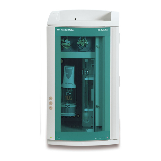
Page 18: Overview Of The Instrument
3.1 Front ■■■■■■■■■■■■■■■■■■■■■■ 3 Overview of the instrument Front Module overview Figure 4 920 Absorber Module – Front Bottle holder Transfer tubing Protects the instrument from contamination Pre-installed. Connects the 10-port valve and provides the space for the liquid con- with the Dosino. - Page 19 Two holders for the two Dosinos. One on Space for the Dosinos, the trap columns and the back panel and one on the side panel. the absorber tube. 11 6-port valve For sample preparation and sample transfer to the analysis instrument. 920 Absorber Module ■■■■■■■■...
-
Page 20: Figure 5 920 Absorber Module - Front
3.1 Front ■■■■■■■■■■■■■■■■■■■■■■ Capillary feed- throughs and cable feed-throughs Figure 5 920 Absorber Module – Front Capillary guides Capillary guide To arrange capillaries and tubings in the For the combustion gas inlet capillary (Com- instrument. bustion Module (AJ)). ■■■■■■■■ 920 Absorber Module... - Page 21 Capillary openings Cable opening For guiding capillaries and tubings out of the For guiding Dosino cables out of the instru- instrument. ment. 920 Absorber Module ■■■■■■■■...
-
Page 22: Rear
3.2 Rear ■■■■■■■■■■■■■■■■■■■■■■ Rear Figure 6 920 Absorber Module – Rear Cable opening PC connection socket For guiding Dosino cables out of the instru- For connecting a computer with a USB ment. cable. USB connection sockets MSB connection sockets Two USB connection sockets for connecting... - Page 23 13 Power socket 14 On/off switch For connecting the power cord. For switching the instrument on and off. CAUTION Do not connect the detectors, as this will cause the instrument to not work correctly anymore. 920 Absorber Module ■■■■■■■■...
-
Page 24: Setting Up The Instrument
The instrument should be protected against excessive temperature fluctua- tions and direct sunlight. Overview Installation of the 920 Absorber Module The 920 Absorber Module is provided with a wide array of accessories. These accessory parts have to be installed before the instrument can be put into operation. Procedure... -
Page 25: Figure 7 Capillaries And Tubings In Use - Overview
Connection between the 10-port valve and Combustion Oven (TEI): PTFE capillary the waste container. 1/8 in. OD / 1/16 in. ID / 5 m Connection between the absorber tube and the Combustion Module (AJ) / Combustion Oven (TEI). 920 Absorber Module ■■■■■■■■... - Page 26 (6.1014.200) and the 6-port valve. Colored sleeves Different liquids move throughout the 920 Absorber Module. In order to provide you an overview of the different flow paths, we recommend using the provided colored sleeves as follows to code the capillaries that route...
-
Page 27: Dosino For Ultrapure Water
Slip the colored sleeve over the capillary and secure it to the desired spot by heating it, for example by using a hairdryer. Dosino for ultrapure water The Dosino for ultrapure water is installed first. 920 Absorber Module ■■■■■■■■... -
Page 28: Figure 8 Installing The Dosino For Ultrapure Water
4.3 Dosino for ultrapure water ■■■■■■■■■■■■■■■■■■■■■■ Figure 8 Installing the Dosino for ultrapure water 13 FEP tubing M6 for 920, 13 cm 14 Combustion Module (AJ): PTFE capil- (6.1805.010) lary 0.5 mm ID / 3 m (6.1803.030) | Combustion Oven (TEI): PTFE capillary Connection between the Dosino with ultra- 0.8 mm ID / 2.5 m (6.07311.310) - Page 29 6-port valve. The Dosino aspirates ultrapure water from the bottle and starts by dosing it to the Metrosep I Trap 1 – 100/4.0 (6.1014.200) through port 1 and to port 5 of the 6-port valve from there. 920 Absorber Module ■■■■■■■■...
-
Page 30: Assembling The Dosino
800 Dosino (2.800.0010) ■ 807 Dosing Unit 5 mL (6.3032.150) ■ Attaching the Dosino to the 807 Dosing Unit The manual for the 800 Dosino describes how to attach the 800 Dosino correctly to a dosing unit. ■■■■■■■■ 920 Absorber Module... -
Page 31: Feeding The Capillary Into The Instrument For Combustion Module (Aj)
Feeding the capillary into the instrument for Combustion Module (AJ) Accessories For this step you need: PTFE capillary (6.1803.030) ■ Colored sleeves, blue ■ Feeding the capillary for the water infeed into the instru- ment 6.1803.030 920 Absorber Module ■■■■■■■■... -
Page 32: Feeding The Capillary Into The Instrument For Combustion Oven (Tei)
The arrows in the figure point in the direction the capillaries have to be pushed. 1 Feeding the capillary for the water infeed into the instru- ment Slide a blue colored sleeve over the capillary far enough that it ■ remains visible outside the instrument. ■■■■■■■■ 920 Absorber Module... -
Page 33: Connecting The Ports - Overview
■ Pressure screw (6.2744.350) ■ Coupling (6.2744.080) ■ FEP tubing M6 for 920 150 cm (6.1805.030) with FEP aspiration tub- ing (6.1819.100) (8- FEP tubing M6 for 920, 13 cm (6.1805.010) (8- Combustion Module (AJ): PTFE capillary (6.1803.030) (8- ■... -
Page 34: Figure 9 Connect The Dosino For Ultrapure Water
The following accessories have to be connected to these 2 ports: Port … install this accessory FEP tubing M6 for 920 150 cm (6.1805.030) with FEP aspiration tub- ing (6.1819.100) (8- PTFE capillary for Combustion Module (AJ) (6.1803.030) (8- ■... - Page 35 Push the pressure screw over the end of the PTFE capillary far ■ enough that a few millimeters of the capillary extend beyond the tip of the pressure screw. Attach the coupling on the pressure screw and tighten it by hand. ■ 920 Absorber Module ■■■■■■■■...
- Page 36 The capillary for the water infeed and the water aspiration tubing can now be connected to the Dosino. Proceed as follows: Connecting port 2 Prerequisites FEP tubing M6 to 920 150 cm (6.1805.030) is threaded in through the ■ thread adapter (6.1618.020) and the Dosino holder (6.2057.230). ■■■■■■■■...
- Page 37 Tighten the FEP tubing on port 2 of the dosing unit. 2 Routing the FEP tubing out of the instrument Guide the loose end of the FEP tubing out of the 920 Absorber Mod- ule through one of the capillary openings on the back panel of the instrument.
- Page 38 The FEP tubing (6.1805.030) and the PTFE capillary for the Combustion Module (AJ) (6.1803.030) or the PTFE capillary for the Combustion Oven (TEI) (6.07311.310) are threaded in through the thread adapter (6.1618.020) and the Dosino holder (6.2057.230) and are connected to the ports 2 and 4. ■■■■■■■■ 920 Absorber Module...
- Page 39 Port 3 on the right side of the Dosino is used for connecting transfer tub- ing. It is used for liquid handling. Accessories The following accessories have to be connected to these 2 ports: 920 Absorber Module ■■■■■■■■...
- Page 40 30 cm of the PTFE capillary (6.1803.030) (8- ■ Pressure screw (6.2744.350) ■ Coupling (6.2744.080) ■ FEP tubing M6 for 920, 13 cm (6.1805.010) (8- For this step you also need: Capillary cutter (6.2621.080) ■ Connecting port 1 1 Cutting the PTFE capillary to size Cut off a piece of the PTFE capillary that is approx.
-
Page 41: Inserting The Dosino In The Instrument
Inserting the Dosino in the instrument CAUTION Space is limited in the 920 Absorber Module. When you insert the fully connected Dosino into the instrument, ensure that none of the tubing or capillaries are bent or kinked. Turn the Dos- ino so that the capillaries and tubing can be as straight as possible. -
Page 42: Connecting The Metrosep I Trap 1
6-port valve. The use of the trap column ensures that the analysis is not distorted by unwanted contamination. ■■■■■■■■ 920 Absorber Module... - Page 43 CAUTION Flow can only move through the trap column in one direction. This flow direction is marked on the column with an engraved arrow. Be absolutely sure to note this flow direction when connecting the capillaries. 920 Absorber Module ■■■■■■■■...
- Page 44 40 cm long using the capillary cutter (6.2621.080) and tighten it onto the outlet of the trap column using a pressure screw. Inserting the trap column in the instrument Insert the Metrosep I Trap 1 – 100/4.0 in the instrument as follows: ■■■■■■■■ 920 Absorber Module...
-
Page 45: Connecting The Ultrapure Water Bottle
4 Installation 1 Fasten the Metrosep I Trap 1 – 100/4.0 in place in the rear holding bracket (4-4) of the 920 Absorber Module using the column head. Next step Tighten the loose end of the PTFE capillary at the outlet of the trap col- umn to port 5 of the 6-port valve (see chapter 4.6, page 62). - Page 46 4 Place the adsorber tube into the large opening of the bottle cap and fasten it in place with the SGJ clip. 5 Seal the M8 opening with a stopper. ■■■■■■■■ 920 Absorber Module...
-
Page 47: Dosino For The Absorber Solution
Connection between the Metrosep A Trap 1 (6.1014.000). - 100/4.0 trap column (6.1014.000) and the Combustion Module (AJ) / Combustion Oven (TEI). 11 FEP tubing M6 for 920 150 cm 12 FEP tubing M6 for 920, 13 cm (6.1805.030) with FEP aspiration tub- (6.1805.010) ing (6.1819.100) Connection between the Dosino with the Aspiration tubing for the absorber solution. -
Page 48: Assembling The Dosino
800 Dosino (2.800.0010) ■ Dosing unit 10 mL (6.3032.210) ■ Attaching the Dosino to the 807 Dosing Unit The manual for the 800 Dosino describes how to attach the 800 Dosino correctly to a dosing unit. ■■■■■■■■ 920 Absorber Module... -
Page 49: Connecting The Ports - Overview
Install this accessory Port 1 FEP tubing M6 for 920, 13 cm (6.1805.010) (10- Port 2 FEP tubing M6 for 920 150 cm (6.1805.030) with FEP aspiration tub- ing (6.1819.100) (10- Port 3 PTFE capillary (6.1803.030), approx. 20 cm (10- ■... -
Page 50: Figure 11 Connect The Dosino For The Absorber Solution
The following accessories have to be connected at port 2: Port Install this accessory Port 2 FEP tubing M6 for 920 150 cm (6.1805.030) with FEP aspiration tub- ing (6.1819.100) (10- For this step you also need: Thread adapter (6.1618.020) ■... - Page 51 Tighten the FEP tubing on port 2 of the dosing unit. 3 Routing the FEP tubing out of the instrument Guide the loose end of the FEP tubing out of the 920 Absorber Mod- ule through one of the capillary openings on the back panel of the instrument.
- Page 52 Accessories The following accessories have to be connected to these two ports: Port Install this accessory Port 1 FEP tubing M6 for 920, 13 cm (6.1805.010) (10- Port 3 PTFE capillary (6.1803.030), approx. 20 cm (10- ■ Pressure screw (6.2744.350) ■...
- Page 53 Push the pressure screw over the end of the PTFE capillary far ■ enough that a few millimeters of the capillary extend beyond the tip of the pressure screw. Attach the coupling on the pressure screw and tighten it by hand. ■ 920 Absorber Module ■■■■■■■■...
-
Page 54: Inserting The Dosino In The Instrument
Inserting the Dosino in the instrument CAUTION Space is limited in the 920 Absorber Module. When you insert the fully connected Dosino into the instrument, ensure that none of the tubing or capillaries are bent or kinked. Turn the Dos- ino so that the capillaries and tubing can be as straight as possible. -
Page 55: Connecting The T Connector
The T connector is connected between the Dosino for ultrapure water, the Dosino for the absorber solution and the transfer tubing. Accessories At inlet … … install this accessory FEP tubing M6 for 920, 13 cm (6.1805.010) from Dosino for absorber solution (7- 920 Absorber Module ■■■■■■■■... - Page 56 4.4 Dosino for the absorber solution ■■■■■■■■■■■■■■■■■■■■■■ At inlet … … install this accessory FEP tubing M6 for 920, 13 cm (6.1805.010) from Dosino for ultra- pure water (7- Transfer tubing (4- Installing the T connector 1 Connecting the FEP tubing Screw the loose end of the FEP tubing connected to port 3 of the Dosino for ultrapure water to an inlet (1) on the T connector.
-
Page 57: Connecting The Metrosep A Trap 1
Combustion Oven (TEI).) Optional: Colored sleeve, yellow ■ Feeding the capillary for the absorber solution into the instrument (Combustion Module (AJ)) Feed the capillary for the absorber solution into the instrument as follows: 920 Absorber Module ■■■■■■■■... -
Page 58: Figure 12 Feeding The Capillary For The Absorber Solution Into The Instrument
Route one end of the PTFE- capillary (6.1803.030) to the front of ■ the instrument from the right side of the instrument through the capillary feed-through between the base tray and the 920 Absorber Module. Thread the end of the capillary through the bottom horizontal ■... - Page 59 CAUTION Flow can only move through the trap column in one direction. This flow direction is marked on the column with an engraved arrow. Be absolutely sure to note this flow direction when connecting the capillaries. 920 Absorber Module ■■■■■■■■...
- Page 60 Screw the PTFE capillary (6.1803.030) with the yellow colored ■ sleeve (fed in from the right side of the instrument) in place on the trap column's outlet using a pressure screw (6.2744.010). Connecting the column's outlet to the Combustion Oven (TEI) ■■■■■■■■ 920 Absorber Module...
-
Page 61: Connecting The Bottle With The Absorber Solution
Clear glass bottle 2 L (6.1608.070) filled with the absorber solution ■ Bottle cap (6.1602.160) ■ FEP tubing M6 for 920, 150 cm (6.1805.030) fastened to port 2 of the ■ Dosino for the absorber solution. Adsorber tube (6.1609.000) ■... - Page 62 M6 opening. Put the loose end of the FEP tubing through the bottle cap's M6 opening and tighten it. NOTE The end of the aspiration tubing has to reach to the bottom of the bottle. ■■■■■■■■ 920 Absorber Module...
-
Page 63: 10-Port-Valve
PEEK capillary, 0.5 mm ID / 15 cm PTFE capillary, 0.75 mm ID / 3 m (6.1831.040) (6.1803.160) Connection between the 6-port valve and Approx. 80 cm. Connection between the the 10-port valve. 10-port valve and the bottle with the standard solution. 920 Absorber Module ■■■■■■■■... -
Page 64: Connecting The Ports
PTFE capillary, 0.75 mm ID / 3 m (6.1803.160), approx. 80 cm ■ (13- Pressure screw (6.2744.090) ■ PTFE capillary, 0.75 mm ID / 3 m (6.1803.160), approx. 80 cm ■ (13- Pressure screw (6.2744.090) ■ Threaded stopper (6.2744.220) ■■■■■■■■ 920 Absorber Module... -
Page 65: Figure 14 Connecting The 10-Port Valve
Screw the adapter in place in the central port. ■ Screw one end of the transfer tubing in place on the adapter. ■ 2 Connecting port 1 Screw the PEEK capillary to port 1 using a long pressure screw. ■ 920 Absorber Module ■■■■■■■■... - Page 66 … 6-port valve (see chapter 4.6, page 62) Bottle with standard solution (see chapter 4.5.2, page 59) Bottle with check standard (see chapter 4.5.3, page 60) Absorber tube (see chapter 4.7, page 68) ■■■■■■■■ 920 Absorber Module...
-
Page 67: Connecting The Bottle With The Standard Solution
Screw the bottle attachment onto the bottle. ■ Push the capillary far enough into the bottle that it reaches the ■ bottom of the bottle. Then fix it in place with a pressure screw. 920 Absorber Module ■■■■■■■■... -
Page 68: Connecting The Bottle With The Check Standard
10-port valve) in through a capillary feed-through between the device and the bottle holder on the side of the instrument. 2 Fasten the capillary in the bottle containing the check standard. Place the bottle on the bottle holder. ■■■■■■■■ 920 Absorber Module... -
Page 69: Function Of The 10-Port Valve
"secured". The secured port is moved to during switching only if it is the target of the switching procedure. If the secured port lies along the shortest route during a valve switchover, then the longer path will automatically be selected. Example: Switching from port 10 to port 7. 920 Absorber Module ■■■■■■■■... -
Page 70: 6-Port Valve
1 – 2 – 3 – 4 – 5 – 6 (see figure 16, left). Figure 16 10-port valve – Normal valve switchover and with a secured port 6-port valve The 6-port valve is connected next. ■■■■■■■■ 920 Absorber Module... -
Page 71: Connecting The Ports
Inlet for sample, standard solution and check 10-port valve standard Outlet for waste Waste container Sample loop 6-port valve – Port 6 Outlet for sample, standard solution and check Injection valve in the IC instrument standard 920 Absorber Module ■■■■■■■■... - Page 72 PTFE capillary, 0.5 mm ID / 3 m (6.1803.030) (17- ■ Pressure screw (6.2744.010) ■ PTFE capillary, 0.5 mm ID / 3 m (6.1803.030), approx. 40 cm ■ (17- Pressure screw (6.2744.010) ■ Sample loop 250 µL (6.1825.290) ■ Pressure screw (6.2744.010) ■ ■■■■■■■■ 920 Absorber Module...
-
Page 73: Figure 18 Connecting The 6-Port Valve
6-port valve through the two capillary guides on the left inside the instrument. Push the pressure screw over the end of the capillary far enough ■ that approx. 4 mm of the capillary is exposed. 920 Absorber Module ■■■■■■■■... -
Page 74: Mode Of Operation Of The 6-Port Valve
6-port valve – Ports Port 1 Port 2 Connected to the 10-port valve. Used as the For connecting the capillary to the waste inlet for the sample and the standard solu- container. tion and check standard. ■■■■■■■■ 920 Absorber Module... -
Page 75: Figure 20 6-Port Valve - Valve Positions
1 into the 6-port valve and directly back out through port 2. In this valve position, the absorber solution in the sample loop is flushed to the analyzer together with the transfer solution. 920 Absorber Module ■■■■■■■■... -
Page 76: Absorber Tube
"Combustion Gas". The absorber tube is connected between the Combustion Module (AJ) / Combustion Oven (TEI) and the 10-port valve. Accessories The following accessories have to be connected to the absorber tube: ■■■■■■■■ 920 Absorber Module... - Page 77 Screw the holder in place on the bottom end of the absorber ■ tube. Check whether the stopper is in place at the upper end of the ■ absorber tube. The following capillaries have to be fastened to the assembled absorber tube. 920 Absorber Module ■■■■■■■■...
- Page 78 Screw the thicker PTFE capillary (21-8) in place on the check valve using a pressure screw (6.2744.170). Combustion Oven (TEI): The PTFE capillary emerges from the back of the oven and must be short- ened to the required length with a capillary cutter. ■■■■■■■■ 920 Absorber Module...
- Page 79 1 Hang the absorber tube on the two brackets on the right inner side wall. Next steps Connect the … to Capillary/ tubing at … side Secure the outlet of the combustion oven (see chapter 4.11.2, page 920 Absorber Module ■■■■■■■■...
-
Page 80: Connecting The Drainage Tubing And Leak Sensor
Accessories For this step you need the following parts from the accessory kit: Vario/ Flex Basic (6.5000.000): 2 × silicone tubing (6.1816.080) ■ You also need scissors. ■■■■■■■■ 920 Absorber Module... -
Page 81: Connecting The Leak Sensor
Route the loose end into a waste container. 4.8.2 Connecting the leak sensor Plugging in the leak sensor connection cable The leak sensor connection cable is coiled up in the base tray. 920 Absorber Module ■■■■■■■■... -
Page 82: Connecting The Instrument To A Computer
USB connecting cable (6.2151.020) ■ Connecting the USB cable 1 Insert the USB cable into the computer connection socket on the rear of the instrument labeled PC. 2 Insert the other end into a USB port on the computer. ■■■■■■■■ 920 Absorber Module... -
Page 83: Connecting The Instrument To The Power Grid
Unplug the power plug immediately if you suspect that moisture has ■ gotten inside the instrument. Only personnel who have been issued Metrohm qualifications may ■ perform service and repair work on electrical and electronic parts. Connecting the power cord... -
Page 84: Connecting The 920 Absorber Module To The Remaining Components
4.11 Connecting the 920 Absorber Module to the remaining components ■■■■■■■■■■■■■■■■■■■■■■ 4.11 Connecting the 920 Absorber Module to the remain- ing components Combustion Module (AJ) Three capillaries are routed out at the right side of the Combustion-IC-Sys- tem. The capillary connected to port 4 of the Dosino for ultrapure water is ■... - Page 85 2 Shortening the capillary Shorten the capillary using the capillary cutter so that it can be connected to the combustion tube's inlet easily. 3 Connecting the capillary Three connections are located at the combustion tube's inlet: 920 Absorber Module ■■■■■■■■...
-
Page 86: Figure 22 Combustion Tube - Inlet
4.11 Connecting the 920 Absorber Module to the remaining components ■■■■■■■■■■■■■■■■■■■■■■ Figure 22 Combustion tube – Inlet Water infeed inlet Flame sensor connection Connection for the capillary with the blue Connection for the flame sensor. colored sleeve (7- Oxygen infeed Sample inlet Connection for the oxygen infeed. -
Page 87: Connecting The Combustion Module (Aj) Outlet: Absorber Solution
(7- removing the combustion gases. Peltier cooler Combustion gases connector For cooling the combustion gases at the Connector for the PTFE capillary, 1/8 in. / combustion tube's outlet. 1/16 in. ID / 1.5 m (6.1803.130) (7- 920 Absorber Module ■■■■■■■■... - Page 88 4.11 Connecting the 920 Absorber Module to the remaining components ■■■■■■■■■■■■■■■■■■■■■■ Connecting the capillary for the combustion gases 1 Feeding the capillary into the Combustion Module (AJ) Push the loose end of the PTFE capillary 1/8 in. / 1/16 in. ID / 1.5 ■...
-
Page 89: Connecting The Combustion Oven (Tei) Inlet
Figure 24 Combustion tube – Inlet Argon infeed Oxygen infeed Connection for the argon infeed. Connection for the oxygen infeed. Oxygen infeed Water infeed inlet Connection for the oxygen infeed. Connector for the ultrapure water supply. 920 Absorber Module ■■■■■■■■... -
Page 90: Connecting The Combustion Oven (Tei) Outlet
4.11 Connecting the 920 Absorber Module to the remaining components ■■■■■■■■■■■■■■■■■■■■■■ 4.11.4 Connecting the Combustion Oven (TEI) outlet Figure 25 Combustion Oven (TEI) – Outlet Absorber solution capillary Combustion gases capillary Capillary for the infeed of absorber solution Capillary for transporting the combustion at the tube outlet. - Page 91 ■ can be connected to the injection valve of the 930 Compact IC Flex easily. Connect the end of the capillary to port 1 of the injection valve ■ (see manual for 930 Compact IC Flex). 920 Absorber Module ■■■■■■■■...
- Page 92 4.11 Connecting the 920 Absorber Module to the remaining components ■■■■■■■■■■■■■■■■■■■■■■ NOTE The process for connecting the respective instruments to a computer or a power supply is described in the respective manuals: 930 Compact IC Flex manual. ■ 920 Absorber Module manual.
-
Page 93: Start-Up
The 920 Absorber Module is installed according to the specifications in ■ the manual for the 920 Absorber Module and is connected to the Combustion Module (AJ) / Combustion Oven (TEI). The 930 Compact IC Flex (2.930.2560) is installed according to the ■... - Page 94 ■ CIC (TEI), Solid Autosampler CIC (TEI) or the GLS Sampler CIC (TEI), if present. Switch on the ion chromatograph and the 920 Absorber Module. ■ MagIC Net detects both instruments and asks if they are to be saved to the device table.
- Page 95 The IC instrument is ready to measure as soon as equilibration has finished. 5 Start the equilibration of the Combustion Oven (TEI) and the Liquid Autosampler CIC (TEI), Solid Autosampler CIC (TEI) or the GLS Sam- pler CIC (TEI), if present, in the TEIS software. 920 Absorber Module ■■■■■■■■...
-
Page 96: Operation And Maintenance
Information regarding the maintenance of the Dosino can be found in the Dosino manual enclosed in your delivery. Alternatively, you can also down- load it from the Internet at www.metrohm.com. Dosing unit Information regarding the maintenance of the Dosino can be found in the Dosino manual enclosed in your delivery. -
Page 97: Metrosep I Trap 1
Information regarding the maintenance of the Metrosep I Trap 1 can be found in the leaflet on the trap column enclosed in your delivery. Alterna- tively, you can also download it from the Internet at www.metrohm.com. Metrosep A Trap 1 Information regarding the maintenance of the Metrosep A Trap 1 can be found in the leaflet on the trap column enclosed in your delivery. - Page 98 Exchanging the absorber tube holder 1 Unscrewing the outlet capillary On the bottom side, unscrew the pressure screw from the absorber tube holder. 2 Unscrewing the check valve holder Unscrew the check valve holder (6.2766.010) from the absorber tube holder. ■■■■■■■■ 920 Absorber Module...
- Page 99 (6.2744.170). 6 Mounting the outlet capillary Tighten the loose end of the capillary (6.1803.160) (connected to port 8 of the 10-port valve) to the bottom of the absorber tube holder using a pressure screw (6.2744.010). 920 Absorber Module ■■■■■■■■...
-
Page 100: Troubleshooting
If you experience problems with the dosing units, you can find informa- tion on troubleshooting in the manual for the 800 Dosino enclosed in the delivery. Alternatively, you can also download it from the Internet at www.metrohm.com. ■■■■■■■■ 920 Absorber Module... -
Page 101: Accessories
Downloading the accessories list 1 Enter https://www.metrohm.com/ into your Internet browser. 2 Enter the article number (e.g. 2.920.0010) into the search field. The search result is displayed. 3 Click on the product. Detailed information regarding the product is shown on various tabs. -
Page 102: Technical Specifications
562 mm Depth 368 mm Weight Without acces- 15.0 kg sories With Dosinos 16.2 kg Base tray, housing Polyurethane hard foam (PUR) with flame retardation for fire class UL and bottle holder 94 V-0, CFC-free, coated material ■■■■■■■■ 920 Absorber Module... -
Page 103: Dosino
Dosino Please refer to the manual for the Dosino enclosed in the delivery for information regarding the technical specifications of the Dosino. Alterna- tively, you can also download it from the Internet at www.metrohm.com. 10-port valve Connections 1 out of 10... -
Page 104: Absorber Tube
USB connector) 2 Mini DIN plugs, 8-pin (female) (for Dosinos) CAUTION When connecting an instrument to the MSB connector you must switch off the 920 Absorber Module. Extension Module 1 15-pin DSUB (female) Detector 2 DSUB 15-pin high-density plugs (female) -
Page 105: Index
Interface ......96 Dosino Technical specifications ..96 For absorber solution ..39 For ultrapure water ..... 19 Voltage ........96 Drainage tubing Material ........94 Installation ......72 MSB ......... 96 Electrostatic charge ....5 920 Absorber Module ■■■■■■■■...
Need help?
Do you have a question about the 920 and is the answer not in the manual?
Questions and answers