Metrohm 916 Ti-Touch Manual - Short Instructions
Hide thumbs
Also See for 916 Ti-Touch:
- Manual (502 pages) ,
- Tutorial (68 pages) ,
- Manual - short instructions (39 pages)
Table of Contents
Advertisement
Advertisement
Table of Contents

Related Manuals for Metrohm 916 Ti-Touch


Summary of Contents for Metrohm 916 Ti-Touch
- Page 1 916 Ti‑Touch Manual – Short Instructions 8.916.8004EN / 2020-03-03...
- Page 3 Metrohm AG CH-9100 Herisau Switzerland Phone +41 71 353 85 85 Fax +41 71 353 89 01 info@metrohm.com www.metrohm.com 916 Ti‑Touch Manual – Short Instructions 8.916.8004EN / 2020-03-03...
- Page 4 Technical Communication Metrohm AG CH-9100 Herisau techcom@metrohm.com This documentation is protected by copyright. All rights reserved. This documentation has been prepared with great care. However, errors can never be entirely ruled out. Please send comments regarding possible errors to the address above.
-
Page 5: Table Of Contents
■■■■■■■■■■■■■■■■■■■■■■ Table of contents Table of contents 1 About these short instructions 2 Introduction Instrument description ............2 2.1.1 Titration and measuring modes ..........2 2.1.2 Connectors ................4 2.1.3 Intended use ................4 About the documentation ........... 5 2.2.1 Symbols and conventions ............ - Page 6 ■■■■■■■■■■■■■■■■■■■■■■ Table of contents 5.6.5 Connecting a PC keyboard ............. 21 5.6.6 Connecting a barcode reader ..........22 5.6.7 Connecting a Sample Processor ..........22 Connecting sensors ............23 5.7.1 General ................. 23 5.7.2 Connecting a pH, metal or ion-selective electrode ....24 5.7.3 Connecting a reference electrode ..........
-
Page 7: About These Short Instructions
■■■■■■■■■■■■■■■■■■■■■■ 1 About these short instructions 1 About these short instructions The present short instructions contain important chapters from the more detailed manual. In addition to an introduction, safety instructions and an overview of the instruments, you will also find information about the installation and operation of the 916 Ti‑Touch in addition to documents regarding conformity and warranty. -
Page 8: Introduction
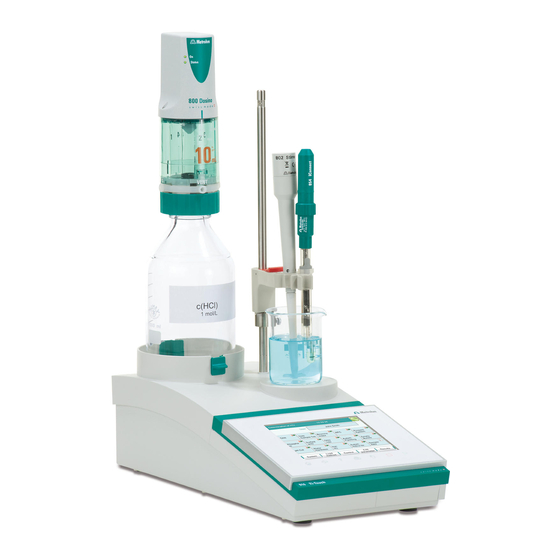
■■■■■■■■■■■■■■■■■■■■■■ 2.1 Instrument description 2 Introduction Instrument description The 916 Ti‑Touch is a compact titration system for volumetric titration. This titrator combines in a single device the touch-sensitive color monitor for convenient and efficient operation, the titration unit and as well as depending on the product version an integrated stirrer interface for a pro- peller stirrer. - Page 9 ■■■■■■■■■■■■■■■■■■■■■■ 2 Introduction ■ Monotonic equivalence point titration. The reagent is added in con- stant volume steps. Measuring modes: – pH (pH measurement) – U (potentiometric voltage measurement) – Ipol (voltametric measurement with selectable polarization cur- rent) – Upol (amperometric measurement with selectable polarization voltage) ■...
-
Page 10: Connectors
The 916 Ti‑Touch is equipped with the following connectors: Power connection ■ For connecting to the power grid using the power supply unit provi- ded. Two MSB connectors (Metrohm Serial Bus) ■ For connecting dosing devices, one additional stirrer or a Remote Box. USB connector ■... -
Page 11: About The Documentation
■■■■■■■■■■■■■■■■■■■■■■ 2 Introduction About the documentation CAUTION Please read through this documentation carefully before putting the instrument into operation. The documentation contains information and warnings which the user must follow in order to ensure safe opera- tion of the instrument. 2.2.1 Symbols and conventions The following symbols and formatting may appear in this documentation:... - Page 12 ■■■■■■■■■■■■■■■■■■■■■■ 2.2 About the documentation NOTE This symbol highlights additional information and tips. ■■■■■■■■ 916 Ti‑Touch...
-
Page 13: Safety Instructions
The electrical safety when working with the instrument is ensured as part of the international standard IEC 61010. WARNING Only personnel qualified by Metrohm are authorized to carry out service work on electronic components. WARNING Never open the housing of the instrument. The instrument could be damaged by this. -
Page 14: Tubing And Capillary Connections
■■■■■■■■■■■■■■■■■■■■■■ 3.3 Tubing and capillary connections Protection against electrostatic charges WARNING Electronic components are sensitive to electrostatic charges and can be destroyed by discharges. Do not fail to pull the power cord out of the power socket before you set up or disconnect electrical plug connections at the rear of the instrument. -
Page 15: Recycling And Disposal
■■■■■■■■■■■■■■■■■■■■■■ 3 Safety instructions Recycling and disposal This product is covered by European Directive 2012/19/EU, WEEE – Waste Electrical and Electronic Equipment. The correct disposal of your old instrument will help to prevent negative effects on the environment and public health. More details about the disposal of your old instrument can be obtained from your local authorities, from waste disposal companies or from your local dealer. -
Page 16: Overview Of The Instrument
■■■■■■■■■■■■■■■■■■■■■■ 4.1 Front of the instrument 4 Overview of the instrument Front of the instrument ‑ Touch Figure 1 Front 916 Ti Display Fixed key [Home] Touch screen. Opens the main dialog. Fixed key [Back] Fixed key [Help] Saves the entry and opens the next-higher Opens the online help for the dialog dis- dialog page. -
Page 17: Rear Of The Instrument
NTC). Two B sockets, 2 mm. Pt wire electrodes. Socket F. MSB connector (MSB 1 and MSB 2) Power socket (Power) Metrohm Serial Bus. For connecting external For connecting the external power supply dosing devices, one additional stirrer or a unit. -
Page 18: Installation
■■■■■■■■■■■■■■■■■■■■■■ 5.1 Setting up the instrument 5 Installation Setting up the instrument 5.1.1 Packaging The instrument is supplied in protective packaging together with the sepa- rately packed accessories. Keep this packaging, as only this ensures safe transportation of the instrument. 5.1.2 Checks Immediately after receipt, check whether the shipment has arrived com-... - Page 19 ■■■■■■■■■■■■■■■■■■■■■■ 5 Installation Figure 3 Connecting the power supply unit Proceed as follows: 1 Connect the plug of the external power supply unit with the mains connection of the Ti‑Touch (see figure 3, page 13). NOTICE The plug of the power supply unit is protected against accidental disconnection of the cable by means of a pull-out protection fea- ture.
-
Page 20: Mounting The Electrode Holder
■■■■■■■■■■■■■■■■■■■■■■ 5.3 Mounting the electrode holder Mounting the electrode holder An electrode or, depending on the product version, a propeller stirrer can be mounted onto the 916 Ti‑Touch with the aid of the electrode holder. NOTICE To prevent damage to the electrode or rod stirrer, the permissible immersion depth of the products applied can be fixed with the aid of the clamping ring on the electrode holder. -
Page 21: Connecting The Propeller Stirrer (Depending On The Product Version)
■■■■■■■■■■■■■■■■■■■■■■ 5 Installation Connecting the propeller stirrer (depending on the product version) The 916 Ti‑Touch is equipped with a built-in magnetic stirrer or a built-in stirrer connector, depending on the product version. You can connect the 802 Stirrer propeller stirrer to the stirrer connector. NOTICE Before the rod stirrer is connected, the electrode holder with the clamp- ing ring must be mounted on the support rod, see (see chapter 5.3,... -
Page 22: Connecting Msb Devices
Connecting MSB devices In order to connect MSB devices, e.g. dosing devices or Remote Box, the Ti‑Touch has two connectors to what is referred to as the Metrohm Serial Bus (MSB). Various peripheral devices can be connected in sequence (daisy chain) at a single MSB connector (8-pin Mini DIN socket) and be control- led simultaneously by the Ti‑Touch. -
Page 23: Connecting A Dosing Device
■■■■■■■■■■■■■■■■■■■■■■ 5 Installation NOTICE When connecting MSB devices together, the following must be observed: No additional stirrer may be connected to the MSB 1! ■ Only one device of the same type may be used at a single MSB con- ■... -
Page 24: Connecting An Additional Stirrer Or Titration Stand
Instruments that are controlled via remote lines and/or that send control signals via remote lines can be connected via the 6.2148.010 Remote Box. In addition to Metrohm, other instrument manufacturers also use similar connectors that make it possible to connect different instruments together. -
Page 25: Connecting Usb Devices
■■■■■■■■■■■■■■■■■■■■■■ 5 Installation 2 Connect the Remote Box connection cable to an MSB connector (2-7) on the rear side of the Ti‑Touch. 3 Switch on the Ti‑Touch. You can connect an 869 Compact Sample Changer. The Remote Box also has an MSB socket at which a further MSB device, e.g. a dosing device, can be connected. -
Page 26: Connecting A Balance
■■■■■■■■■■■■■■■■■■■■■■ 5.6 Connecting USB devices Connect the printer as follows: 1 With the aid of the 6.2151.020 cable, connect the USB connector of the Ti‑Touch (type A) with the USB connector of the printer (type B, see manual for the printer). 2 Configure the printer in the device manager of the Ti‑Touch. -
Page 27: Connecting A Pc Keyboard
■■■■■■■■■■■■■■■■■■■■■■ 5 Installation Balance Cables Sartorius MP8, MC, LA, Genius, 6.2134.060 Cubis Shimadzu BX, BW 6.2125.080 + 6.2125.010 Connect the balance as follows: 1 Connect the USB plug of the USB/RS-232 adapter with the USB con- nector of the Ti‑Touch (Type A). The USB/RS-232 adapter will be recognized automatically and entered in the device manager of the Ti‑Touch. -
Page 28: Connecting A Barcode Reader
■■■■■■■■■■■■■■■■■■■■■■ 5.6 Connecting USB devices 5.6.6 Connecting a barcode reader The barcode reader is used as an aid for text and numerical input. You can connect a barcode reader with USB interface. Connect the barcode reader as follows: 1 Connect the USB plug of the barcode reader with the USB connector of the Ti‑Touch (Type A). -
Page 29: Connecting Sensors
■■■■■■■■■■■■■■■■■■■■■■ 5 Installation The 6.2151.000 controller cable is required for connecting a Sample Pro- cessor. Connect the Sample Processor as follows: 1 Connect the Sample Processor to the power grid. 2 Connect the Sample Processor to the Ti‑Touch with the controller cable. -
Page 30: Connecting A Ph, Metal Or Ion-Selective Electrode
■■■■■■■■■■■■■■■■■■■■■■ 5.7 Connecting sensors 5.7.2 Connecting a pH, metal or ion-selective electrode Connect the pH, metal or ion-selective electrode as follows: 1 Plug the electrode plug into the Ind. socket of the Ti‑Touch. Figure 7 Connecting a pH, metal or ion-selective electrode NOTICE The electrode cable is protected against accidental disconnection of the cable by means of a pull-out protection. -
Page 31: Connecting A Polarizable Electrode
■■■■■■■■■■■■■■■■■■■■■■ 5 Installation Figure 8 Connecting a reference electrode 5.7.4 Connecting a polarizable electrode Connect the polarizable electrode as follows: 1 Plug the electrode plug into the Pol. socket of the Ti‑Touch. Figure 9 Connecting a polarizable electrode (stirrer connector; not available, depending on the product version) ■■■■■■■■... -
Page 32: Connecting The Temperature Sensor Or Electrode With Integrated Temperature Sensor
■■■■■■■■■■■■■■■■■■■■■■ 5.7 Connecting sensors NOTICE The electrode cable is protected against accidental disconnection of the cable by means of a pull-out protection. If you wish to pull out the plug again, you first need to pull back the outer plug sleeve. -
Page 33: Connecting The Iconnect
■■■■■■■■■■■■■■■■■■■■■■ 5 Installation NOTICE The red plug must always be plugged into the red socket for the purpose of shielding against disruptions. If you use an electrode with an integrated NTC sensor, then you must plug the red plug into the red socket. 5.7.6 Connecting the iConnect The external measuring interface 854 iConnect can be connected to the... - Page 34 ■■■■■■■■■■■■■■■■■■■■■■ 5.7 Connecting sensors The 854 iConnect can also be connected while the instrument is switched 1 Plug the plug of the 854 iConnect (3) into the socket of the mini USB adapter cable (2). Observe the correct orientation (markings). Figure 12 Plugging in the 854 iConnect As soon as the instrument is switched on, the 854 iConnect is detec-...
- Page 35 ■■■■■■■■■■■■■■■■■■■■■■ 5 Installation Figure 14 Aligning the guide pin 3 Attach the electrode to the 854 iConnect. Figure 15 Attaching the electrode The guide pin guarantees correct connection in such a way that the contact pins cannot be damaged. 4 Tighten the screw cap by hand. If there is an electrode in the sensor list of the firmware or software, the electrode is detected automatically when connecting it.
-
Page 36: Differential Potentiometry
■■■■■■■■■■■■■■■■■■■■■■ 5.7 Connecting sensors Figure 16 Unplugging the 854 iConnect 2 Leave the mini USB adapter cable (2) plugged into the socket of the instrument (1). NOTICE Position the mini USB adapter cable in such a way that it cannot be removed by accident. -
Page 37: Connecting The Ti-Touch To A Network
■■■■■■■■■■■■■■■■■■■■■■ 5 Installation Connecting the Ti‑Touch to a network The 916 Ti‑Touch has a network connection (Ethernet). This can be used to integrate your Ti‑Touch in your network. You can, for example, store data on a PC within the network or print reports on a network printer. You will find information as to which settings are necessary for the network connection in the Device manager chapter contained in the more detailed manual. -
Page 38: Operation
■■■■■■■■■■■■■■■■■■■■■■ 6.1 Switching the instrument on and off 6 Operation Switching the instrument on and off Switching on the instrument CAUTION Peripheral devices (e.g., printers) must be connected and switched on before you switch on the 916 Ti‑Touch. NOTICE English is set as the default dialog language when the instrument is switched on for the first time. - Page 39 ■■■■■■■■■■■■■■■■■■■■■■ 6 Operation NOTICE If a buret unit is connected, then a request appears to carry out the Prepare function: All tubings and the cylinder are rinsed with the Prepare function. The preparing of the buret unit is described in the chapter Manual control of the detailed manual.
-
Page 40: Fundamentals Of Operation
■■■■■■■■■■■■■■■■■■■■■■ 6.2 Fundamentals of operation Proceed as follows: 1 Press the power switch on the left-hand side of the back panel of the 916 Ti‑Touch. The current data is saved and the system is shut down. This process takes just a short time. At the same time, all other instruments con- nected to the 916 Ti‑Touch via a USB cable are also being switched off. -
Page 41: Display Elements And Controls
■■■■■■■■■■■■■■■■■■■■■■ 6 Operation 6.2.2 Display elements and controls The following display elements and controls are available: Table 1 Fixed keys which are always available [Home] always opens the main dialog. [Back] saves the entry and opens the next-higher dialog page. [Help] opens the online help for the dialog displayed. -
Page 42: Status Display
■■■■■■■■■■■■■■■■■■■■■■ 6.2 Fundamentals of operation Inactive buttons with gray lettering indicate that the respective function is not available at the moment. Input fields open an input dialog when tapped. Tapping on the selection symbol opens a selec- tion list. A check box can also be activated or deactiva- ted by tapping on it. -
Page 43: Entering Text And Numbers
■■■■■■■■■■■■■■■■■■■■■■ 6 Operation 6.2.4 Entering text and numbers In the editing dialog for text or numerical input, enter the individual char- acters by tapping in the input field. The following functions are available: Text editor Table 4 Editing functions [OK] The modification is applied and the editing dialog is exited. - Page 44 ■■■■■■■■■■■■■■■■■■■■■■ 6.2 Fundamentals of operation Number editor Table 5 Editing functions [OK] The modification is applied and the editing dialog is exited. [Cancel] The editing dialog is exited without applying the modification. [Delete entry] The content of the input field is deleted com- pletely.
-
Page 45: Maintenance
Maintenance The electronic and mechanical functional groups of Metrohm instruments can and should be checked by specialist personnel from Metrohm as part of a regular preventive maintenance schedule. Please ask your local Metrohm representative regarding the precise terms and conditions involved in concluding a corresponding maintenance agreement. - Page 46 Supply voltage ......7 Barcode reader ....22 MET ........... 3 Switch off ......... 33 Dosing device ..... 17 Metrohm Serial Bus MSB, see also Switch on ......... 32 MSB devices ....... 16 "MSB" ........16 PC keyboard ....... 21 Power supply unit ....
Need help?
Do you have a question about the 916 Ti-Touch and is the answer not in the manual?
Questions and answers