Metrohm 916 Ti‑Touch Manual
Hide thumbs
Also See for 916 Ti‑Touch:
- Tutorial (68 pages) ,
- Manual - short instructions (46 pages) ,
- Manual - short instructions (39 pages)
Advertisement
Quick Links
Advertisement

Related Manuals for Metrohm 916 Ti‑Touch


Summary of Contents for Metrohm 916 Ti‑Touch
- Page 1 916 Ti‑Touch Manual 8.916.8005EN / 2020-03-03...
- Page 3 Metrohm AG CH-9100 Herisau Switzerland Phone +41 71 353 85 85 Fax +41 71 353 89 01 info@metrohm.com www.metrohm.com 916 Ti‑Touch Programmversion 5.916.0041 Manual 8.916.8005EN / 2020-03-03...
- Page 4 Technical Communication Metrohm AG CH-9100 Herisau techcom@metrohm.com This documentation is protected by copyright. All rights reserved. This documentation has been prepared with great care. However, errors can never be entirely ruled out. Please send comments regarding possible errors to the address above.
- Page 5 ■■■■■■■■■■■■■■■■■■■■■■ Table of contents Table of contents 1 Introduction Instrument description ............1 1.1.1 Titration and measuring modes ..........1 1.1.2 Connectors ................3 1.1.3 Intended use ................3 About the documentation ........... 4 1.2.1 Symbols and conventions ............4 2 Safety instructions General notes on safety ............
- Page 6 ■■■■■■■■■■■■■■■■■■■■■■ Table of contents 4.6.7 Connecting a Sample Processor ..........21 Connecting sensors ............22 4.7.1 General ................. 22 4.7.2 Connecting a pH, metal or ion-selective electrode ....23 4.7.3 Connecting a reference electrode .......... 23 4.7.4 Connecting a polarizable electrode ........24 4.7.5 Connecting the temperature sensor or electrode with inte- grated temperature sensor .............
- Page 7 E-mail ..................98 11.3.2 PC/LIMS report ..............99 11.3.3 Shared memory ..............100 11.3.4 TCP/IP settings ..............102 11.4 Metrohm control instruments ......... 103 11.4.1 Properties – Measuring input ..........104 11.4.2 Properties – MSB connector ..........105 ■■■■■■■■ 916 Ti‑Touch...
- Page 8 ■■■■■■■■■■■■■■■■■■■■■■ Table of contents 11.4.3 Properties – Peripheral devices ..........106 11.5 Sample Processor ............. 106 11.5.1 Properties – Sample Processor ..........107 11.5.2 Properties – Tower ............... 108 11.5.3 Properties – Swing Head ............110 11.6 Sample racks ..............114 11.6.1 Editing rack data ..............
- Page 9 ■■■■■■■■■■■■■■■■■■■■■■ Table of contents 14.4 Assigning a result automatically to a common varia- ble ..................158 15 Templates 15.1 Sample data ..............160 15.1.1 Sample identification list ............161 15.1.2 Sample assignment table ............. 162 15.2 Custom result templates ..........164 15.2.1 Editing result templates ............
- Page 10 ■■■■■■■■■■■■■■■■■■■■■■ Table of contents 20 Sample data 20.1 Entering sample data in the main dialog ....... 207 20.2 Requesting sample data at the start of the determina- tion ..................208 21 Sample table 21.1 General ................210 21.2 Editing sample data ............213 21.3 Properties ................
- Page 11 ■■■■■■■■■■■■■■■■■■■■■■ Table of contents 26 Result table 26.1 Properties ................250 26.2 Saving the result table ............. 254 26.3 Loading the result table ........... 254 27 Printing 27.1 General report options ............. 257 27.2 Settings of the individual reports ........258 27.3 List of all printable reports ..........
- Page 12 ■■■■■■■■■■■■■■■■■■■■■■ Table of contents 29.2.5 Control instrument .............. 318 29.2.6 Sensor ................. 318 29.2.7 Dosing device ..............320 29.2.8 Stirrer .................. 321 29.3 Endpoint titrations (SET) ..........322 29.3.1 Start conditions ..............322 29.3.2 Control parameters .............. 323 29.3.3 Titration parameters ............327 29.3.4 Stop conditions ..............
- Page 13 ■■■■■■■■■■■■■■■■■■■■■■ Table of contents 29.9 Evaluations (EVAL) ............376 29.9.1 Fixed endpoint evaluation (EVAL FIX-EP) ....... 377 29.9.2 pK value and half neutralization potential evaluation (EVAL pK/HNP) ................378 29.9.3 Minimum and maximum evaluation (EVAL MIN/MAX) ..379 29.9.4 Break point evaluation (EVAL BREAK) ........381 29.9.5 Rate evaluation (EVAL RATE) ..........
- Page 14 32.6 Result variables as parameter setting ......444 32.7 Electrode calibration with Sample Processors ....445 32.8 Stored buffer series for pH calibration ......447 32.8.1 Metrohm ................447 32.8.2 NIST (according to DIN standard 19266, 2015) ....448 32.8.3 DIN (according to DIN standard 19267, 2012) .....
- Page 15 ■■■■■■■■■■■■■■■■■■■■■■ Table of contents 32.10 Diagnosis ................465 32.10.1 LCD test ................466 32.10.2 Formatting an external storage medium ....... 466 32.10.3 Removing an external storage medium ........ 467 32.10.4 Adjusting the touch screen ..........467 32.10.5 Testing the touch screen ............468 32.10.6 Software update (loading program versions and language files) ..................
- Page 16 ■■■■■■■■■■■■■■■■■■■■■■ Table of figures Table of figures Figure 1 Front 916 Ti‑Touch ................9 Figure 2 916 Ti‑Touch rear ................10 Figure 3 Connecting the power supply unit ........... 12 Figure 4 Connecting the propeller stirrer ............14 Figure 5 MSB connections ................
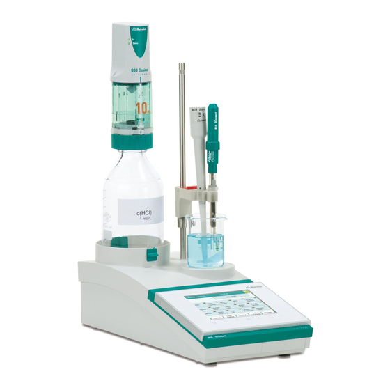
- Page 17 ■■■■■■■■■■■■■■■■■■■■■■ 1 Introduction 1 Introduction Instrument description The 916 Ti‑Touch is a compact titration system for volumetric titration. This titrator combines in a single device the touch-sensitive color monitor for convenient and efficient operation, the titration unit and as well as depending on the product version an integrated stirrer interface for a pro- peller stirrer.
- Page 18 ■■■■■■■■■■■■■■■■■■■■■■ 1.1 Instrument description ■ Monotonic equivalence point titration. The reagent is added in con- stant volume steps. Measuring modes: – pH (pH measurement) – U (potentiometric voltage measurement) – Ipol (voltametric measurement with selectable polarization cur- rent) – Upol (amperometric measurement with selectable polarization voltage) ■...
- Page 19 The 916 Ti‑Touch is equipped with the following connectors: Power connection ■ For connecting to the power grid using the power supply unit provi- ded. Two MSB connectors (Metrohm Serial Bus) ■ For connecting dosing devices, one additional stirrer or a Remote Box. USB connector ■...
- Page 20 ■■■■■■■■■■■■■■■■■■■■■■ 1.2 About the documentation About the documentation CAUTION Please read through this documentation carefully before putting the instrument into operation. The documentation contains information and warnings which the user must follow in order to ensure safe opera- tion of the instrument. 1.2.1 Symbols and conventions The following symbols and formatting may appear in this documentation:...
- Page 21 ■■■■■■■■■■■■■■■■■■■■■■ 1 Introduction NOTE This symbol highlights additional information and tips. ■■■■■■■■ 916 Ti‑Touch...
- Page 22 The electrical safety when working with the instrument is ensured as part of the international standard IEC 61010. WARNING Only personnel qualified by Metrohm are authorized to carry out service work on electronic components. WARNING Never open the housing of the instrument. The instrument could be damaged by this.
- Page 23 ■■■■■■■■■■■■■■■■■■■■■■ 2 Safety instructions Protection against electrostatic charges WARNING Electronic components are sensitive to electrostatic charges and can be destroyed by discharges. Do not fail to pull the power cord out of the power socket before you set up or disconnect electrical plug connections at the rear of the instrument.
- Page 24 ■■■■■■■■■■■■■■■■■■■■■■ 2.5 Recycling and disposal Recycling and disposal This product is covered by European Directive 2012/19/EU, WEEE – Waste Electrical and Electronic Equipment. The correct disposal of your old instrument will help to prevent negative effects on the environment and public health. More details about the disposal of your old instrument can be obtained from your local authorities, from waste disposal companies or from your local dealer.
- Page 25 ■■■■■■■■■■■■■■■■■■■■■■ 3 Overview of the instrument 3 Overview of the instrument Front of the instrument ‑ Touch Figure 1 Front 916 Ti Display Fixed key [Home] Touch screen. Opens the main dialog. Fixed key [Back] Fixed key [Help] Saves the entry and opens the next-higher Opens the online help for the dialog dis- dialog page.
- Page 26 NTC). Two B sockets, 2 mm. Pt wire electrodes. Socket F. MSB connector (MSB 1 and MSB 2) Power socket (Power) Metrohm Serial Bus. For connecting external For connecting the external power supply dosing devices, one additional stirrer or a unit.
- Page 27 ■■■■■■■■■■■■■■■■■■■■■■ 4 Installation 4 Installation Setting up the instrument 4.1.1 Packaging The instrument is supplied in protective packaging together with the sepa- rately packed accessories. Keep this packaging, as only this ensures safe transportation of the instrument. 4.1.2 Checks Immediately after receipt, check whether the shipment has arrived com- plete and without damage by comparing it with the delivery note.
- Page 28 ■■■■■■■■■■■■■■■■■■■■■■ 4.2 Connecting the power supply unit Figure 3 Connecting the power supply unit Proceed as follows: 1 Connect the plug of the external power supply unit with the mains connection of the Ti‑Touch (see figure 3, page 12). NOTICE The plug of the power supply unit is protected against accidental disconnection of the cable by means of a pull-out protection fea- ture.
- Page 29 ■■■■■■■■■■■■■■■■■■■■■■ 4 Installation Mounting the electrode holder An electrode or, depending on the product version, a propeller stirrer can be mounted onto the 916 Ti‑Touch with the aid of the electrode holder. NOTICE To prevent damage to the electrode or rod stirrer, the permissible immersion depth of the products applied can be fixed with the aid of the clamping ring on the electrode holder.
- Page 30 ■■■■■■■■■■■■■■■■■■■■■■ 4.4 Connecting the propeller stirrer (depending on the product version) Connecting the propeller stirrer (depending on the product version) The 916 Ti‑Touch is equipped with a built-in magnetic stirrer or a built-in stirrer connector, depending on the product version. You can connect the 802 Stirrer propeller stirrer to the stirrer connector.
- Page 31 Connecting MSB devices In order to connect MSB devices, e.g. dosing devices or Remote Box, the Ti‑Touch has two connectors to what is referred to as the Metrohm Serial Bus (MSB). Various peripheral devices can be connected in sequence (daisy chain) at a single MSB connector (8-pin Mini DIN socket) and be control- led simultaneously by the Ti‑Touch.
- Page 32 ■■■■■■■■■■■■■■■■■■■■■■ 4.5 Connecting MSB devices NOTICE When connecting MSB devices together, the following must be observed: No additional stirrer may be connected to the MSB 1! ■ Only one device of the same type may be used at a single MSB con- ■...
- Page 33 Instruments that are controlled via remote lines and/or that send control signals via remote lines can be connected via the 6.2148.010 Remote Box. In addition to Metrohm, other instrument manufacturers also use similar connectors that make it possible to connect different instruments together.
- Page 34 ■■■■■■■■■■■■■■■■■■■■■■ 4.6 Connecting USB devices 2 Connect the Remote Box connection cable to an MSB connector (2-7) on the rear side of the Ti‑Touch. 3 Switch on the Ti‑Touch. You can connect an 869 Compact Sample Changer. The Remote Box also has an MSB socket at which a further MSB device, e.g.
- Page 35 ■■■■■■■■■■■■■■■■■■■■■■ 4 Installation 1 With the aid of the 6.2151.020 cable, connect the USB connector of the Ti‑Touch (type A) with the USB connector of the printer (type B, see manual for the printer). 2 Configure the printer in the device manager of the Ti‑Touch (see chapter 11.7, page 123).
- Page 36 ■■■■■■■■■■■■■■■■■■■■■■ 4.6 Connecting USB devices Balance Cables Sartorius MP8, MC, LA, Genius, 6.2134.060 Cubis Shimadzu BX, BW 6.2125.080 + 6.2125.010 Connect the balance as follows: 1 Connect the USB plug of the USB/RS-232 adapter with the USB con- nector of the Ti‑Touch (Type A). The USB/RS-232 adapter will be recognized automatically and entered in the device manager of the Ti‑Touch.
- Page 37 ■■■■■■■■■■■■■■■■■■■■■■ 4 Installation 4.6.6 Connecting a barcode reader The barcode reader is used as an aid for text and numerical input. You can connect a barcode reader with USB interface. Connect the barcode reader as follows: 1 Connect the USB plug of the barcode reader with the USB connector of the Ti‑Touch (Type A).
- Page 38 ■■■■■■■■■■■■■■■■■■■■■■ 4.7 Connecting sensors The 6.2151.000 controller cable is required for connecting a Sample Pro- cessor. Connect the Sample Processor as follows: 1 Connect the Sample Processor to the power grid. 2 Connect the Sample Processor to the Ti‑Touch with the controller cable.
- Page 39 ■■■■■■■■■■■■■■■■■■■■■■ 4 Installation 4.7.2 Connecting a pH, metal or ion-selective electrode Connect the pH, metal or ion-selective electrode as follows: 1 Plug the electrode plug into the Ind. socket of the Ti‑Touch. Figure 7 Connecting a pH, metal or ion-selective electrode NOTICE The electrode cable is protected against accidental disconnection of the cable by means of a pull-out protection.
- Page 40 ■■■■■■■■■■■■■■■■■■■■■■ 4.7 Connecting sensors Figure 8 Connecting a reference electrode 4.7.4 Connecting a polarizable electrode Connect the polarizable electrode as follows: 1 Plug the electrode plug into the Pol. socket of the Ti‑Touch. Figure 9 Connecting a polarizable electrode (stirrer connector; not available, depending on the product version) ■■■■■■■■...
- Page 41 ■■■■■■■■■■■■■■■■■■■■■■ 4 Installation NOTICE The electrode cable is protected against accidental disconnection of the cable by means of a pull-out protection. If you wish to pull out the plug again, you first need to pull back the outer plug sleeve. 4.7.5 Connecting the temperature sensor or electrode with integrated temperature sensor...
- Page 42 ■■■■■■■■■■■■■■■■■■■■■■ 4.7 Connecting sensors NOTICE The red plug must always be plugged into the red socket for the purpose of shielding against disruptions. If you use an electrode with an integrated NTC sensor, then you must plug the red plug into the red socket. 4.7.6 Connecting the iConnect The external measuring interface 854 iConnect can be connected to the...
- Page 43 ■■■■■■■■■■■■■■■■■■■■■■ 4 Installation The 854 iConnect can also be connected while the instrument is switched 1 Plug the plug of the 854 iConnect (3) into the socket of the mini USB adapter cable (2). Observe the correct orientation (markings). Figure 12 Plugging in the 854 iConnect As soon as the instrument is switched on, the 854 iConnect is detec- ted automatically and entered as measuring input into the device...
- Page 44 ■■■■■■■■■■■■■■■■■■■■■■ 4.7 Connecting sensors Figure 14 Aligning the guide pin 3 Attach the electrode to the 854 iConnect. Figure 15 Attaching the electrode The guide pin guarantees correct connection in such a way that the contact pins cannot be damaged. 4 Tighten the screw cap by hand.
- Page 45 ■■■■■■■■■■■■■■■■■■■■■■ 4 Installation Figure 16 Unplugging the 854 iConnect 2 Leave the mini USB adapter cable (2) plugged into the socket of the instrument (1). NOTICE Position the mini USB adapter cable in such a way that it cannot be removed by accident.
- Page 46 ■■■■■■■■■■■■■■■■■■■■■■ 4.8 Connecting the Ti‑Touch to a network Connecting the Ti‑Touch to a network The 916 Ti‑Touch has a network connection (Ethernet). This can be used to integrate your Ti‑Touch in your network. You can, for example, store data on a PC within the network or print reports on a network printer. In Chapter 11, page 95, you will find information as to which settings are necessary for the network connection.
- Page 47 ■■■■■■■■■■■■■■■■■■■■■■ 5 Titrations 5 Titrations Dynamic equivalence point titration (DET) Dynamic equivalence point titration is a titration mode for all standard titrations with an s-shaped curve progression. The reagent is added in vari- able volume steps. The volume steps vary as a function of the slope of the curve.
- Page 48 ■■■■■■■■■■■■■■■■■■■■■■ 5.3 Endpoint titration (SET) Endpoint titration (SET) Endpoint titration is a titration mode for rapid routine determinations to a preset endpoint (e.g. titrations in accordance with special standards) and titrations for which reagent overflow must be avoided. The titration termi- nation at the endpoint takes place either volume drift-controlled or after a waiting time.
- Page 49 ■■■■■■■■■■■■■■■■■■■■■■ 5 Titrations Dosing outside the control range ■ The dosing rate increases continuously during this phase. It starts with the Min. rate and increases to the Max. rate. The dosing continues to be carried out at the Max. rate until the Control range is reached. In this range, STAT mode and SET mode control equally.
- Page 50 ■■■■■■■■■■■■■■■■■■■■■■ 5.5 Manual titration (MAT) In addition, the method can be equipped with further commands, e.g. calculating a result, creating a report or scanning sample data. The system is FDA compliant and enables a manual titration according to the FDA guidelines with this mode. ■■■■■■■■...
- Page 51 ■■■■■■■■■■■■■■■■■■■■■■ 6 Operation 6 Operation Switching the instrument on and off Switching on the instrument CAUTION Peripheral devices (e.g., printers) must be connected and switched on before you switch on the 916 Ti‑Touch. NOTICE English is set as the default dialog language when the instrument is switched on for the first time.
- Page 52 ■■■■■■■■■■■■■■■■■■■■■■ 6.2 Fundamentals of operation Confirm the message with [OK]. ■ The main dialog is displayed: Switching off the instrument CAUTION The 916 Ti‑Touch must be switched off by pressing the power switch on the rear of the instrument before the electricity supply is interrupted. If this is not done, then there is a danger of data loss.
- Page 53 ■■■■■■■■■■■■■■■■■■■■■■ 6 Operation 6.2.2 Display elements and controls The following display elements and controls are available: Table 1 Fixed keys which are always available [Home] always opens the main dialog. [Back] saves the entry and opens the next-higher dialog page. [Help] opens the online help for the dialog displayed.
- Page 54 ■■■■■■■■■■■■■■■■■■■■■■ 6.2 Fundamentals of operation Inactive buttons with gray lettering indicate that the respective function is not available at the moment. Input fields open an input dialog when tapped. Tapping on the selection symbol opens a selec- tion list. A check box can also be activated or deactiva- ted by tapping on it.
- Page 55 ■■■■■■■■■■■■■■■■■■■■■■ 6 Operation 6.2.4 Entering text and numbers In the editing dialog for text or numerical input, enter the individual char- acters by tapping in the input field. The following functions are available: Text editor Table 4 Editing functions [OK] The modification is applied and the editing dialog is exited.
- Page 56 ■■■■■■■■■■■■■■■■■■■■■■ 6.2 Fundamentals of operation Number editor Table 5 Editing functions [OK] The modification is applied and the editing dialog is exited. [Cancel] The editing dialog is exited without applying the modification. [Delete entry] The content of the input field is deleted com- pletely.
- Page 57 ■■■■■■■■■■■■■■■■■■■■■■ 7 System settings 7 System settings Main dialog: System ▶ System settings This chapter describes the various system settings and configurations. Selecting the dialog language (see chapter 7.1.1, page 41). ■ Setting the date and time (see chapter 7.1.2, page 42). ■...
- Page 58 ■■■■■■■■■■■■■■■■■■■■■■ 7.1 General system settings 2 Selecting the dialog language Tap on the Dialog language list box and select the desired lan- ■ guage. 3 Saving the settings Tap on the fixed keys [ ] or [ The main dialog is displayed in the respective dialog language. 7.1.2 Setting the date, time and local time The Ti‑Touch displays the date and time in accordance with ISO standard...
- Page 59 ■■■■■■■■■■■■■■■■■■■■■■ 7 System settings 4 Enter the local time Tap on the list box Local time - UTC and select the difference ■ from the UTC (Coordinated Universal Time). The selection off means that the time is saved with no difference from the UTC.
- Page 60 Operation without login function: ■ In the main dialog, enter User = Metrohm. Operation with login function: ■ A user who works with expert dialog must log in.
- Page 61 ■■■■■■■■■■■■■■■■■■■■■■ 7 System settings 2 Deactivate fixed keys Deactivate those fixed keys which are not permitted to be used. 3 Saving the settings Tap on the fixed keys [ ] or [ Deactivated fixed keys cannot be used. Configuring the routine dialog A suitable Standard configuration has already been saved for routine operations: Methods can only be loaded, but not modified or created.
- Page 62 ■■■■■■■■■■■■■■■■■■■■■■ 7.3 User administration 2 Deactivate buttons Deactivate those buttons which are not permitted to be used. All deactivated buttons will appear grayed-out, i.e. they are inactive. 3 Deactivate other functions Many additional buttons and parameters can be disabled in the dia- logs of [System], [Load method], [Control], [Edit parameters] and [Results].
- Page 63 ■■■■■■■■■■■■■■■■■■■■■■ 7 System settings The following data is displayed in the user list for each user: Name ■ Dialog mode in which the user may operate the system. ■ Status ■ You can use the user list two different ways: Operation with login function: ■...
- Page 64 ■■■■■■■■■■■■■■■■■■■■■■ 7.3 User administration NOTICE Once users have worked with the login function and password protec- tion, they can no longer be deleted, even if the password protection is disabled again. The status of these users must be set to inactive (requirement of FDA Guidance 21 CFR Part 11).
- Page 65 ■■■■■■■■■■■■■■■■■■■■■■ 7 System settings Dialog Dialog mode in which the user may operate the system. Selection Expert dialog | Routine dialog Expert dialog All functions that are supported by the system are available. Routine dialog The user dialog can be limited for routine operations. Only selected functions are available (see Configuring the routine dialog, page 45).
- Page 66 ■■■■■■■■■■■■■■■■■■■■■■ 7.3 User administration Authorizations for using and signing methods can be defined in this dia- log. These settings are only effective if you are working with the login function enabled and password protection. Use only released methods on | off (Default value: off) If this option is activated, then the user may only start methods that have been released.
- Page 67 ■■■■■■■■■■■■■■■■■■■■■■ 7 System settings Review determinations (signature level 1) on | off (Default value: off) If this option is activated, then the user may only sign determinations at the first level. The determination is assigned the status reviewed. Release determinations (signature level 2) on | off (Default value: off) If this option is activated, then the user may only sign determinations at the second level.
- Page 68 ■■■■■■■■■■■■■■■■■■■■■■ 7.3 User administration 3 Create the identification profile Tap on [Create ID profile]. The user configuration and the current routine dialog settings are saved. 7.3.3 Defining login options Main dialog: System ▶ System settings ▶ User admin. ▶ Login options There are a number of different ways to log onto the system: Without login...
- Page 69 ■■■■■■■■■■■■■■■■■■■■■■ 7 System settings Login via user name on | off (Default value: off) If this option is activated, then the user must log in with his or her unam- biguous identification. Login via identification profile on | off (Default value: off) If this option is activated, then the login will take place via USB storage medium with the identification profile stored on it.
- Page 70 ■■■■■■■■■■■■■■■■■■■■■■ 7.3 User administration [Reasons] Predefining a list of reasons which can be selected for the modification/ signature of a method or determination (see chapter 7.3.6, page 56). [Modific. options] Defining the modifications for which a reason is required (see chapter 7.3.5, page 56).
- Page 71 ■■■■■■■■■■■■■■■■■■■■■■ 7 System settings Special characters required on | off (Default value: off) If this option is activated, then the password must contain one of the fol- lowing special characters: ° § + ¦ @ * # ç % & ¬ ( ) = ' ^ ` ~ ] [ } { - _ : . ; , > <...
- Page 72 ■■■■■■■■■■■■■■■■■■■■■■ 7.3 User administration 5 Restore the user list Create the user list again and redefine the login options. 7.3.5 Modification options Main dialog: System ▶ System settings ▶ User admin. ▶ Login options ▶ Modific. options In the dialog Login options / Modification options, you can define for which actions a reason must be entered.
- Page 73 ■■■■■■■■■■■■■■■■■■■■■■ 7 System settings [New] Add a new reason to the list. [Delete] Delete the selected reason from the list. [Edit] Change the designation of the selected reason. 7.3.7 Audit Trail Main dialog: System ▶ System settings ▶ User admin. ▶ Login options ▶...
- Page 74 ■■■■■■■■■■■■■■■■■■■■■■ 7.3 User administration Security log on | off (Default value: off) If this option is activated, then the following events will be recorded: user login/logout, password changes, automatic deactivation of users and mes- sages displayed during the login procedure. User administration log on | off (Default value: off) If this option is activated, then all changes with respect to user administra-...
- Page 75 ■■■■■■■■■■■■■■■■■■■■■■ 7 System settings Measured value display Main dialog: System ▶ System settings ▶ Meas. value display The number of decimal places can be defined for pH values and voltages. This setting refers exclusively to the display of the measured values in the live display and in the manual control.
- Page 76 ■■■■■■■■■■■■■■■■■■■■■■ 8 Titrants Main dialog: System ▶ Titrants This chapter describes how you can create a list of titrants used in the sys- tem. Titrants can be used in intelligent buret units or in nonintelligent buret units. Intelligent buret units have a built-in data chip on which the data for the titrant is stored.
- Page 77 ■■■■■■■■■■■■■■■■■■■■■■ 8 Titrants Data on exchange/dosing unit: ■ – Parameters for the function PREP – Length and diameter of the tubings – Port assignment of the dosing unit – Cylinder volume – Serial number – etc. etc. ■ NOTICE If data is read out from the data chip, then a check is made whether the titrant list already contains a titrant of the same type with the iden- tical serial number.
- Page 78 ■■■■■■■■■■■■■■■■■■■■■■ 8.2 Editing titrant data Editing titrant data Titrant list: Titrants ▶ New / Edit All of the data for the selected titrant is displayed in the dialog Titrants / Edit. Titrant The designation of the titrant is used for unambiguous identification. Entry 24 characters maximum Selection...
- Page 79 ■■■■■■■■■■■■■■■■■■■■■■ 8 Titrants Unit of the titer. 10 characters maximum Entry empty Default value µmol/mL | mmol/L | mol/L | g/L | mg/L | mg/mL | Selection µg/L | ppm | % | mEq/L NOTICE If you modify the titer or the concentration of the titrant in a loaded determination at a later date and would then like to recalculate the determination with the corrected value, then you must modify the value in the determination data under View data / Titrant data (see "Cali-...
- Page 80 ■■■■■■■■■■■■■■■■■■■■■■ 8.3 Monitoring the working life Monitoring the working life Titrant: Edit ▶ Working life In the dialog Edit titrant / Working life, you can define the time inter- val after which the titrant must be replaced. This is particularly important if your titrant has a limited working life.
- Page 81 ■■■■■■■■■■■■■■■■■■■■■■ 8 Titrants Display message A message is displayed. You can select whether you want to continue with the determination or cancel the run. Document message In the determination data it will be documented, that the time interval has been expired. Cancel determination The determination is stopped.
- Page 82 ■■■■■■■■■■■■■■■■■■■■■■ 8.4 Dosing unit Cylinder volume Cylinder volume of the dosing unit. It will be read out automatically on dosing units with integrated data chips. Selection 2 | 5 | 10 | 20 | 50 Default value Serial no. cyl. Serial number of the dosing cylinder.
- Page 83 ■■■■■■■■■■■■■■■■■■■■■■ 8 Titrants Dosing rate Dos. port 1 Rate used for the aspiration and ejection of the reagent via dosing port 1. Input range 0.01 - 166.00 mL/min Selection maximum Default value maximum maximum The maximum dosing rate depends on the cylinder volume (see chap- ter 32.1, page 438).
- Page 84 ■■■■■■■■■■■■■■■■■■■■■■ 8.4 Dosing unit 8.4.2 Tubing parameters Titrant: Edit ▶ Dosing unit ▶ Tubing param. You can enter the length and diameter of the connected tubings in the dialog Dosing unit / Tubing parameters. The values which have already been entered correspond to the dimensions of the supplied stan- dard tubings.
- Page 85 ■■■■■■■■■■■■■■■■■■■■■■ 8 Titrants Length Length of the tubing. Input range 0.0 - 999.9 cm Default value 0.0 cm The setting 0.0 means that this tubing will neither be rinsed nor emptied. Diameter Diameter of the tubing. Input range 0.0 - 9.9 mm Default value 2.0 mm Fill port...
- Page 86 ■■■■■■■■■■■■■■■■■■■■■■ 8.4 Dosing unit Input range 0.0 - 999.9 cm Default value 0.0 cm The setting 0.0 means that this tubing will neither be rinsed nor emptied. Diameter Diameter of the tubing. Input range 0.0 - 9.9 mm Default value 2.0 mm Figure 22 Dosing unit –...
- Page 87 ■■■■■■■■■■■■■■■■■■■■■■ 8 Titrants 8.4.3 Shift direction of the valve disk Titrant: Edit ▶ Dosing unit ▶ Valve disk In this dialog, you can specify the shift direction of the valve disk. Direction Shift direction of the valve disc. descending | ascending | automatic | not over Selection automatic Default value...
- Page 88 ■■■■■■■■■■■■■■■■■■■■■■ 8.5 Exchange unit You can edit data for the exchange unit of the titrant in this dialog. Name Designation of the exchange or dosing unit. Entry 24 characters maximum Default value empty Order number Order number of the exchange or dosing unit. It will be read out automat- ically on units with integrated data chips.
- Page 89 ■■■■■■■■■■■■■■■■■■■■■■ 8 Titrants 8.5.1 Parameters for the preparation (PREP) Titrant: Edit ▶ Exchange unit ▶ PREP param. In the dialog Exchange unit / PREP parameters, you can adjust the parameters for the execution of the Prepare function (command PREP). This function is used to rinse the cylinder and tubings of the exchange unit and fill it air bubble-free.
- Page 90 ■■■■■■■■■■■■■■■■■■■■■■ 8.5 Exchange unit 8.5.2 Tubing parameters Titrant: Edit ▶ Exchange unit ▶ Tubing param. You can enter the length and diameter of the connected tubings in the dialog Exchange unit / Tubing parameters. The values which have already been entered correspond to the dimensions of the supplied stan- dard tubings.
- Page 91 ■■■■■■■■■■■■■■■■■■■■■■ 8 Titrants Diameter Diameter of the tubing. Input range 0.0 - 9.9 mm Default value 2.0 mm Figure 23 Exchange unit – tubing connections Tubing to the reagent bottle Tubing to the dosing tip Tubing to the dosing cylinder GLP test for exchange unit and dosing unit Titrant: Edit ▶...
- Page 92 ■■■■■■■■■■■■■■■■■■■■■■ 8.6 GLP test for exchange unit and dosing unit Monitoring on | off (Default value: off) If this parameter is activated, then the time interval after which a GLP test has to be carried out again will be monitored. GLP test interval If you define a time interval for the GLP test, then the date in Next GLP test will be tracked automatically.
- Page 93 ■■■■■■■■■■■■■■■■■■■■■■ 8 Titrants Titer determination options and data Titrant: Edit ▶ Titer options Detailed information concerning the titer determination is displayed in the Edit titrant / Titer options dialog: Titer method ■ Method by which the titer was determined. If the titer was entered manually, then manual will be displayed.
- Page 94 ■■■■■■■■■■■■■■■■■■■■■■ 8.7 Titer determination options and data Titer validity If you define a time interval for the validity of the titer, then the date in Next titer determ. will be tracked automatically. Input range 1 - 999 days Default value 999 days Next titer determ.
- Page 95 ■■■■■■■■■■■■■■■■■■■■■■ 8 Titrants NOTICE If multiple determinations have been carried out in order to determine the titer, then only one entry will be made in the history. [Delete History] Delete the entire history. [Graph] Open the diagram of the titer values, see following chapter. Dialog "History / Graph"...
- Page 96 ■■■■■■■■■■■■■■■■■■■■■■ 9.1 Editing reagent data 9 Reagents Main dialog: System ▶ Reagents This chapter describes how you can create a list of the reagents used in the system. The list of reagents gives the designation and type of each reagent. [New] Add a new reagent to the list, see following chapter.
- Page 97 ■■■■■■■■■■■■■■■■■■■■■■ 9 Reagents Reagent The designation of the reagent is used for unambiguous identification. Entry 24 characters maximum Comment 24 characters maximum Entry [Reagent monitoring] Set the parameters for the reagent monitoring, see following chapter. Reagent monitoring The conditions for the monitoring of the reagent are defined in the dialog Edit reagent / Reagent monitoring.
- Page 98 ■■■■■■■■■■■■■■■■■■■■■■ 9.2 Reagent monitoring at the end of the determination. ■ Number of determ. The number of determinations to be carried out with a certain amount of reagent depends on the type of sample and its amount. Input range 1 - 999 Selection Default value Working life...
- Page 99 ■■■■■■■■■■■■■■■■■■■■■■ 9 Reagents auto If a monitored parameter has reached the limit set, the method defined below is started automatically. Memory This parameter can only be edited with Reagent replacement = auto. Memory location the method is loaded from. All memory locations are selectable, even if they are currently not accessible.
- Page 100 ■■■■■■■■■■■■■■■■■■■■■■ 10 Sensors Main dialog: System ▶ Sensors This chapter describes how you can create a list of the sensors used in the system. Three standard sensors are defined in the sensor list: pH electrode, Metal electrode and Temperature sensor. These sensors cannot be deleted or renamed.
- Page 101 ■■■■■■■■■■■■■■■■■■■■■■ 10 Sensors NOTICE If data is read out from the data chip of an intelligent sensor, then a check is made whether the sensor list already contains a sensor of the same serial number. If this is the case, then the older data set will always be overwritten by the new data set, no matter whether the data set in the sensor list or the data set on the data chip is the most recent one.
- Page 102 ■■■■■■■■■■■■■■■■■■■■■■ 10.2 Editing the sensor data 10.2 Editing the sensor data Sensor list: Sensor ▶ New / Edit All of the data for the selected sensor is displayed in the dialog Sensors / Edit. Sensor The designation of the sensor is used for unambiguous identification. Entry 24 characters maximum Order number...
- Page 103 ■■■■■■■■■■■■■■■■■■■■■■ 10 Sensors Defining the limit values for monitoring the slope and the electrode zero point (see chapter 10.5, page 92). [Calibration interval] This button is displayed only for pH electrodes. Define the time interval for the next calibration (see chapter 10.6, page 93).
- Page 104 ■■■■■■■■■■■■■■■■■■■■■■ 10.4 Calibration data (for pH electrodes only) Action Selection of the action which is carried out when the time interval has expired. Selection Display message | Document message | Cancel determination Default value Display message For all three options it is documented in the deter- mination data (see dialog More determination data / Messages), that the time interval has been expired.
- Page 105 [Initial data] This button is only displayed for intelligent sensors. Display the initial calibration data determined at the time of the Metrohm quality control. [GLP test] Define the time interval for the GLP test (see "Dialog "Calibration data / GLP test"", page 90).
- Page 106 ■■■■■■■■■■■■■■■■■■■■■■ 10.4 Calibration data (for pH electrodes only) 10.4.1 Properties of the previous calibrations Dialog "Calibration data / History" Sensor: Edit ▶ Calibration data ▶ History The date, time and calibration data of the last ten calibrations are dis- played in tabular form in the dialog Calibration data / History. Calibra- tions that were carried out automatically will be displayed in green;...
- Page 107 ■■■■■■■■■■■■■■■■■■■■■■ 10 Sensors GLP test date Date on which the last GLP test was carried out. After you have carried out an electrode test (ELT command), the date of the electrode test is automatically entered into this field. However, you also can enter the date manually.
- Page 108 ■■■■■■■■■■■■■■■■■■■■■■ 10.5 Limit values for the calibration data 10.5 Limit values for the calibration data Sensor: Edit ▶ Limit values You can define the following limit values in the dialog Edit sensor / Limit values: Slope (pH electrodes) ■ Electrode zero point (pH electrodes) ■...
- Page 109 ■■■■■■■■■■■■■■■■■■■■■■ 10 Sensors Monitoring pH(0) on | off (Default value: off) This parameter is only available with pH electrodes. If this parameter is activated, then the electrode zero point pH(0) will be monitored. Lower limit Input range –20.000 - 20.000 Default value 6.750 Upper limit...
- Page 110 ■■■■■■■■■■■■■■■■■■■■■■ 10.6 Monitoring the calibration interval (for pH electrodes only) Action Selection of the action which is carried out when the time interval has expired. Selection Display message | Document message | Cancel determination Default value Display message For all three options it is documented in the deter- mination data (see dialog More determination data / Messages), that the time interval has been expired.
- Page 111 ■■■■■■■■■■■■■■■■■■■■■■ 11 Device manager 11 Device manager Main dialog: System ▶ Device manager This chapter describes how you can configure the Ti‑Touch, a Sample Pro- cessor and the connected peripheral devices. A detailed description of the hardware installation of the Sample Processor can be found in the corre- sponding installation manual.
- Page 112 The description of the individual instruments can be found in the follow- ing specific chapters: Ti‑Touch (see chapter 11.3, page 97) ■ Metrohm control instruments (see chapter 11.4, page 103) ■ Sample Processor (see chapter 11.5, page 106) ■ Printer (see chapter 11.7, page 123) ■...
- Page 113 ■■■■■■■■■■■■■■■■■■■■■■ 11 Device manager 11.3 Ti‑Touch Instrument list: 916 Ti‑Touch ▶ Edit Device name This designation is used for identification purposes when selecting control devices (command, manual control). Entry 24 characters maximum Comment Entry 24 characters maximum Switch off display If this time interval has expired without the Ti‑Touch having been oper- ated, then the display will be switched off.
- Page 114 ■■■■■■■■■■■■■■■■■■■■■■ 11.3 Ti‑Touch The "Control Remote Box" is the interface via which the system can be started and stopped externally. If multiple Remote Boxes are connected, then the one that is recognized first when the program starts will be used as the "Control Remote Box."...
- Page 115 Mail server Address of the mail server for outgoing mail, e.g. mail.metrohm.ch. You can find the address of the mail server either in your e-mail program set- tings or obtain it from your IT department.
- Page 116 ■■■■■■■■■■■■■■■■■■■■■■ 11.3 Ti‑Touch the first time a PC/LIMS report is generated. All three memory locations are listed as possible selections, even if they cannot be accessed at the moment. off | External memory 1 | External memory 2 | Selection Shared memory Default value The report will not be saved as a file.
- Page 117 ■■■■■■■■■■■■■■■■■■■■■■ 11 Device manager CAUTION If the computer on which you share a memory location does not have the same subnet as the Ti‑Touch, then a WINS server must be present. The computer must be entered in this server. Computer Host name of the computer on which a memory location is to be shared.
- Page 118 ■■■■■■■■■■■■■■■■■■■■■■ 11.3 Ti‑Touch Entry max. 32 characters Default value empty [Connect] Establish the network connection. If the connection has been set up cor- rectly, then all of the input fields will become inactive and the label switches to [Disconnect]. The network connection can be disconnected with this.
- Page 119 Unambiguous designation of the device within the network. This parame- ter cannot be edited. 11.4 Metrohm control instruments The following Metrohm devices can be used as control instruments: Ti-Touch Titrator (permanently entered as control instrument in the ■ device manager) Sample Processors ■...
- Page 120 ■■■■■■■■■■■■■■■■■■■■■■ 11.4 Metrohm control instruments Properties of the MSB connectors (see chapter 11.4.2, page 105) ■ Properties of the peripheral devices on the MSB connector (see chapter ■ 11.4.3, page 106) 11.4.1 Properties – Measuring input Instrument list: Control instrument ▶ Edit ▶ Measuring input 1 ▶...
- Page 121 Input range 1000 - 99999 ohm Default value 30000 ohm The default value applies to Metrohm sensors with an NTC sensor. B value This parameter can only be edited with Type = NTC. Material constant of the NTC sensor. B values of NTC sensors are fre- quently based on different reference temperatures (usually 25 °C and...
- Page 122 ■■■■■■■■■■■■■■■■■■■■■■ 11.5 Sample Processor Switch on on | off (Default value: on) If this parameter is activated, then you will be requested to prepare the dosing device when the Ti‑Touch is switched on. Attach an exchange or dosing unit on | off (Default value: on) If this parameter is activated, then you will be requested to prepare the dosing device when the exchange/dosing unit is attached.
- Page 123 We recommend to carry out a service after 1,000 operating hours. A reset of the running time meter can only be carried out by a Metrohm service engineer. [Properties] Open the properties dialog of the highlighted entry.
- Page 124 ■■■■■■■■■■■■■■■■■■■■■■ 11.5 Sample Processor Comment Entry 24 characters maximum Program version Program version of the instrument software. Serial number Shows the serial number of the device. Rack name Name of the currently attached sample rack. [Adjustment data] Display the internal adjustment data (EEPROM data) of the Sample Pro- cessor.
- Page 125 ■■■■■■■■■■■■■■■■■■■■■■ 11 Device manager Maximum stroke path Lowest permissible lift position for automatic and manual operation. This is a safety setting. A correct specification of this value can prevent the glass of an electrode from breaking, because a titration head can not be moved below the position specified.
- Page 126 ■■■■■■■■■■■■■■■■■■■■■■ 11.5 Sample Processor for 810 Sample Processor: Input range 100.0 - 300.0 mm Default value 166.0 mm 11.5.3 Properties – Swing Head Instrument list: Sample Processor ▶ Edit ▶ Swing Head ▶ Properties The dialog Edit device / Properties shows a list of all external positions with the assigned swing angle and the specific work position for each.
- Page 127 ■■■■■■■■■■■■■■■■■■■■■■ 11 Device manager Properties which apply to all four external positions can be defined in the dialog Properties / Edit external positions 1-4. Shift position Lift position at which the robotic arm rotates to the external positions. Input range 0 - 'Maximum stroke path' mm Default value 0 mm...
- Page 128 ■■■■■■■■■■■■■■■■■■■■■■ 11.5 Sample Processor Properties – Robotic arm Swing Head: Properties ▶ Robotic arm Properties of the robotic arm can be defined in the dialog Properties / Robotic arm. Swing offset The swing offset is a physical angle offset of a specific robotic arm model. The required values can be found in the leaflet for the robotic arm.
- Page 129 ■■■■■■■■■■■■■■■■■■■■■■ 11 Device manager Rotation offset The rotation offset is the offset from the center of the tower to the center of the robotic arm. This value does not usually need to be changed. If a Swing Head is to be mounted on the tower with a lateral offset, then this value can be determined by the service technician when the rack is adjus- ted.
- Page 130 The following data is displayed in the list: Rack ■ Name of the sample rack. Metrohm standard racks are designated by their order numbers. ■■■■■■■■ 916 Ti‑Touch...
- Page 131 Edit the data of the selected sample rack (see chapter 11.6.1, page 116). Loading the sample rack When you receive the file for a new sample rack from your Metrohm rep- resentative, you can easily import this file into your existing system. Pro-...
- Page 132 ■■■■■■■■■■■■■■■■■■■■■■ 11.6 Sample racks Tap on [Show files]. ■ The list with the saved sample rack files is opened. 3 Load the sample rack file Select the desired file. ■ Tap on [Load]. ■ The new sample rack is now loaded and appears in the list of avail- able racks.
- Page 133 ■■■■■■■■■■■■■■■■■■■■■■ 11 Device manager You can edit the data of the selected rack in the dialog Sample rack / Edit rack data. Beaker radius samples Actual radius of the sample vessels at the general sample positions of the rack. This beaker radius may not be less than the minimum beaker radius defined in the tower properties (see "Min.
- Page 134 ■■■■■■■■■■■■■■■■■■■■■■ 11.6 Sample racks Special beaker 1…n If a special beaker is selected as the first calibration position, then the number of buffers used for calibration will determine the number of special beakers to be defined. Any rack position can be defined as a special beaker.
- Page 135 ■■■■■■■■■■■■■■■■■■■■■■ 11 Device manager These positions can be moved to directly under manual control and with the LIFT command. Only lift positions within the maximum stroke path can be entered. This is defined in the device properties of the tower. NOTICE These lift positions can also be assigned directly in manual control after moving to the desired lift height (see chapter 28.6.1, page 281).
- Page 136 ■■■■■■■■■■■■■■■■■■■■■■ 11.6 Sample racks Input range 0 - 'maximum stroke path' mm A lift position of 0 mm corresponds to the "home position", i.e. the lift is located at the upper stop position. The maximum stroke path is defined in the properties of the tower (see "Maximum stroke path", page 109).
- Page 137 ■■■■■■■■■■■■■■■■■■■■■■ 11 Device manager Rack position Number of rack position for selected special beaker. Any rack position can be defined as a special beaker. It is, however, preferable to set them at high rack positions in order to be able to begin sample series at rack posi- tion 1.
- Page 138 ■■■■■■■■■■■■■■■■■■■■■■ 11.6 Sample racks No check takes place. 11.6.2 Rack adjustment Instrument list: Sample Processor ▶ Edit ▶ Racks ▶ Edit ▶ Adjust rack If necessary, each sample rack can be finely adjusted, i.e. the rack offset is determined in the direction of rotation. The adjustment of a rack is usually not necessary.
- Page 139 ■■■■■■■■■■■■■■■■■■■■■■ 11 Device manager Finish the adjustment with [OK]. ■ The lift is moved to the uppermost stop. 11.7 Printer Instrument list: Printer ▶ Edit The list of devices always includes a printer, even if no corresponding device is connected. In this dialog, you also define when you would like to have a report generated as a PDF file.
- Page 140 ■■■■■■■■■■■■■■■■■■■■■■ 11.7 Printer The reports will not be printed out on paper. Connector Selection of the connection type for the printer. Selection USB | Ethernet Default value Local printer at a USB interface. Ethernet Network printer. NOTICE The Ti‑Touch prints the reports with a fixed resolution of 300 dpi. If you are using a printer with a resolution of 360 dpi (or a multiple thereof, e.g.
- Page 141 ■■■■■■■■■■■■■■■■■■■■■■ 11 Device manager Shared memory The report will be saved in a shared directory on the network. The shared directory is selected in the Edit device / Shared memory dia- log (see chapter 11.3.3, page 100). Copy or extract content allowed on | off (Default value: on) If this option is activated, then content can be copied or deleted from the PDF file.
- Page 142 ■■■■■■■■■■■■■■■■■■■■■■ 11.7 Printer Print server Host name of the print server or the computer on which the network printer is configured. If you are working with Windows, then you will find the host name as follows: In the Windows command prompt window, enter the command ipconfig -all.
- Page 143 ■■■■■■■■■■■■■■■■■■■■■■ 11 Device manager 11.7.3 More options Paper size Selection of the paper size. NOTICE The paper size selected will be ignored when the report is printed on a CUSTOM NEOS printer. Selection A4 (210 mm x 297 mm) | Letter (216 mm x 279 mm) Default value A4 (210 mm x 297 mm)
- Page 144 ■■■■■■■■■■■■■■■■■■■■■■ 11.8 Balance Device name Here you can enter a device name of your choice. Entry 24 characters maximum Comment Entry 24 characters maximum Balance type If you have connected a balance, then you have to specify the balance type here. AND | Mettler | Mettler AT | Mettler AX | Selection Ohaus | Precisa | Sartorius | Shimadzu...
- Page 145 ■■■■■■■■■■■■■■■■■■■■■■ 11 Device manager 11.9 USB/RS-232 adapter List of devices: USB/RS-232 adapter ▶ Edit ▶ COM interface ▶ Edit As a rule, balances are equipped with a serial RS-232 interface. To connect a balance, you will require the 6.2148.050 cable. You can adjust the inter- face parameters in the dialog Edit device / Port parameters.
- Page 146 ■■■■■■■■■■■■■■■■■■■■■■ 11.10 PC keyboard Selection even | odd | none Default value none Stop bits Number of stop bits. Selection 1 | 2 Default value Handshake Type of data transfer protocol. NOTICE In case of communication problems, try the software handshake (Soft- ware (XON/XOFF)).
- Page 147 ■■■■■■■■■■■■■■■■■■■■■■ 11 Device manager Device name Here you can enter a device name of your choice. Entry 24 characters maximum Comment Entry 24 characters maximum Keyboard layout Define the country-specific keyboard layout here. English US | German DE | French FR | Spanish Selection ES | German CH English US...
- Page 148 ■■■■■■■■■■■■■■■■■■■■■■ 11.11 Barcode reader NOTICE The lettering of the USB keyboard may differ from above lettering, depending on the country-specific keyboard used. 11.11 Barcode reader List of devices: Barcode reader ▶ Edit A barcode reader can be connected to read in sample data or other texts. A connected barcode reader will be recognized automatically and entered in the list of devices with default settings.
- Page 149 ■■■■■■■■■■■■■■■■■■■■■■ 11 Device manager Barcode input target Selection of the input field for the character string read in by the barcode reader. Selection Active input field | Method | Identification 1 | Identification 2 | Sample size Active input field The character string is entered in the input field of the opened text- or number-input dialog.
- Page 150 ■■■■■■■■■■■■■■■■■■■■■■ 12.1 Managing files 12 File manager Main dialog: System ▶ File manager The saved methods, determinations, sample tables, etc. are managed in the file manager. You can also create a backup of your system (all data and settings). Similarly, an existing backup can be reloaded. The file memory is organized as follows: Internal memory ■...
- Page 151 ■■■■■■■■■■■■■■■■■■■■■■ 12 File manager NOTICE If you use an external storage medium with the FAT or FAT32 file sys- tem, then you can save a maximum of 999 files per group. If you find it necessary to store more than 999 files in a single group, then you must reformat the storage medium with the file system ExFAT (see chapter 32.10.2, page 466).
- Page 152 ■■■■■■■■■■■■■■■■■■■■■■ 12.1 Managing files [Copy] Copy the selected file to a different memory location (see chapter 12.1.1, page 136). [Delete] Delete the selected file. [Load] Load the selected file. 12.1.1 Copying a file Proceed as follows to copy a file: 1 Selecting the file Select the desired file.
- Page 153 ■■■■■■■■■■■■■■■■■■■■■■ 12 File manager 12.1.3 File properties File manager: Internal memory / External memory 1 / External memory 2 ▶ Show all / Show files ▶ Properties Detailed information concerning the file is displayed in the Show files / Properties dialog. They can be edited to a certain extent. File name ■...
- Page 154 ■■■■■■■■■■■■■■■■■■■■■■ 12.2 External storage medium 12.2 External storage medium [Backup] Creating a backup of all data and settings on this storage medium (see chapter 12.3, page 140). [Restore] Load the backup. This function is active only if a backup is available (see chapter 12.3, page 140).
- Page 155 ■■■■■■■■■■■■■■■■■■■■■■ 12 File manager Directory structure The directory structure appears as follows on the external storage medium: Figure 24 Directory structure on the external storage medium Backup All of the files of the backup are stored in this directory. The directory will be created the first time a backup is created.
- Page 156 ■■■■■■■■■■■■■■■■■■■■■■ 12.3 Creating backups / Restoring data 12.3 Creating backups / Restoring data File manager: External memory 1 / External memory 2 You can use the [Backup] function to easily create a backup containing all the data and settings of your system. You should make a backup at regular intervals in order to avoid data loss.
- Page 157 ■■■■■■■■■■■■■■■■■■■■■■ 12 File manager Restorable data blocks The following data blocks can be loaded individually: Methods ■ All of the methods stored in the internal memory. Sample table ■ Current sample table. Result table ■ Current result table. Current determination data ■...
- Page 158 Create a list with your test tools (see chapter 13.2, page 143). ■ Define a service interval for having routine maintenance carried out by ■ a Metrohm service technician (see chapter 13.5, page 152). Define an interval for the regular performance of backups (see chapter ■ 13.5, page 152).
- Page 159 If a result is shown in red, then an error occurred when the respective test was carried out. Switch the Ti‑Touch off and back on again. If the error still occurs pleased notify Metrohm Service. Print report at system start...
- Page 160 ■■■■■■■■■■■■■■■■■■■■■■ 13.3 GLP tests for measurement and titration [Delete] Delete the selected test tool from the list. [Edit] Change the designation of the selected test tool. 13.3 GLP tests for measurement and titration Main dialog: System ▶ GLP manager ▶ GLP tests HW/SW ▶ GLP test "Measurement"...
- Page 161 ■■■■■■■■■■■■■■■■■■■■■■ 13 GLP manager Select the hardware used for the test (see "Dialogs "GLP test ■ "Measurement" / Hardware" and "GLP test "Titration" / Hard- ware"", page 147). Tap on the fixed key [ ■ The dialog GLP tests HW/SW / GLP test "Measurement" appears again.
- Page 162 ■■■■■■■■■■■■■■■■■■■■■■ 13.3 GLP tests for measurement and titration [GLP test interval] Defining the time interval for the GLP test (see "Dialogs "GLP test "Mea- surement" / Test interval" and "GLP test "Titration" / Test interval"", page 146). [Hardware] Documenting the hardware with which the GLP test was carried out (see "Dialogs "GLP test "Measurement"...
- Page 163 ■■■■■■■■■■■■■■■■■■■■■■ 13 GLP manager Display message A message is displayed. You can select whether you want to continue with the determination or cancel the run. Document message In the determination data it will be documented, that the time interval has been expired. Cancel determination The determination is stopped.
- Page 164 ■■■■■■■■■■■■■■■■■■■■■■ 13.4 System validation 13.4 System validation Main dialog: System ▶ GLP manager ▶ System validation In the dialog GLP manager / System validation and its subdialogs, you can document the system validation results and define the time interval after which validation must be carried out again. Proceed as follows: 1 Open the properties dialog In the System / GLP manager dialog, tap on the [System vali-...
- Page 165 ■■■■■■■■■■■■■■■■■■■■■■ 13 GLP manager The dialog GLP manager / System validation appears again. 5 Insert a note Tap on [Note (SOP)]. ■ Enter a brief description, e.g. a summary of the SOP (standard ■ operating procedure) according to which the system validation was carried out (see ""System validation / Note (SOP)"...
- Page 166 ■■■■■■■■■■■■■■■■■■■■■■ 13.4 System validation [Test statistics] Documenting the statistical data of the system validation (see ""System validation / Test statistics" dialog", page 151). "System validation / Note (SOP)" dialog In this dialog, you can enter a brief text, e.g. a summary of the SOP (stan- dard operating procedure) according to which the system validation was carried out.
- Page 167 ■■■■■■■■■■■■■■■■■■■■■■ 13 GLP manager Display message A message is displayed. You can select whether you want to continue with the determination or cancel the run. Document message In the determination data it will be documented, that the time interval has been expired. Cancel determination The determination is stopped.
- Page 168 Main dialog: System ▶ GLP manager ▶ Monitoring ▶ Service inter- In the dialog GLP manager / Service interval, you can define the time interval for the maintenance of the system by the Metrohm Service department. The service interval is checked each time the system is started.
- Page 169 ■■■■■■■■■■■■■■■■■■■■■■ 13 GLP manager Monitoring on | off (Default value: off) If this parameter is activated, then the time interval after which a backup has to be created again will be monitored. Backup interval If you define a time interval for the creation of backups, then the date in Next backup will be tracked automatically.
- Page 170 ■■■■■■■■■■■■■■■■■■■■■■ 14 Common variables Main dialog: System ▶ Common variables You can save 25 method-independent variables, or common variables. These variables can be used in future calculations (as variables CV01… CV25). Common variables are useful, e.g. for the following applications: Determination of a blank value which will be taken into account during ■...
- Page 171 ■■■■■■■■■■■■■■■■■■■■■■ 14 Common variables 14.1 Editing common variables List of common variables: Common Variable ▶ Edit The common variables can be modified as follows: Edit manually, see the following. ■ Automatic assignment from the determination run. A calculation result ■ must be configured accordingly for this purpose (see chapter 14.4, page 158).
- Page 172 ■■■■■■■■■■■■■■■■■■■■■■ 14.2 Properties of common variables Next assignment This parameter is displayed only if a validity has been defined for the com- mon variable. Date on which the validity of the common variable expires. Format: YYYY:MM:DD [Validity] Defining the time interval for the validity of the common variable (see chapter 14.3, page 157).
- Page 173 ■■■■■■■■■■■■■■■■■■■■■■ 14 Common variables 14.3 Monitoring validity Common variable: Edit ▶ Validity In the dialog Edit common variables / Validity, you can define the time interval after which a new value must be assigned to the common variable. Last assignment Date on which the common variable was last assigned a value.
- Page 174 ■■■■■■■■■■■■■■■■■■■■■■ 14.4 Assigning a result automatically to a common variable Document message In the determination data it will be documented, that the time interval has been expired. Cancel determination The determination is stopped. 14.4 Assigning a result automatically to a common varia- NOTICE This instruction is based on the assumption that the method contains a calculation command with a calculation.
- Page 175 ■■■■■■■■■■■■■■■■■■■■■■ 14 Common variables 3 Saving the settings Tap on the fixed keys [ ] or [ In the future, the calculated result will be assigned to the selected common variable (result name, value and unit). ■■■■■■■■ 916 Ti‑Touch...
- Page 176 ■■■■■■■■■■■■■■■■■■■■■■ 15.1 Sample data 15 Templates Main dialog: System ▶ Templates You have the option of defining system-specific templates. You can use these templates when editing the respective data. You can create the following templates: Sample data (see chapter 15.1, page 160) ■...
- Page 177 ■■■■■■■■■■■■■■■■■■■■■■ 15 Templates Sample identifications (see chapter 15.1.1, page 161) ■ List with sample identifications. If you must enter the sample identifica- tion before starting a determination, then you can select the entries contained in this list. Sample assignments (see chapter 15.1.2, page 162) ■...
- Page 178 ■■■■■■■■■■■■■■■■■■■■■■ 15.1 Sample data You can create a system-specific list with sample identifications in the dia- log Sample data / Sample identification list. This list makes it easier for you to enter frequently used sample identifications, i.e. this list is avail- able to you for entering them (main dialog, command REQUEST, etc.).
- Page 179 ■■■■■■■■■■■■■■■■■■■■■■ 15 Templates In the sample assignment table, a particular method is assigned to a sam- ple identification. In this way, you ensure that your samples will be pro- cessed with the correct method; mix-ups are not longer possible. When you start a determination, you need only enter the sample identification;...
- Page 180 ■■■■■■■■■■■■■■■■■■■■■■ 15.2 Custom result templates Entry 32 characters maximum Selection Selection of methods stored in the selected memory 15.2 Custom result templates Main dialog: System ▶ Templates ▶ Custom result templates In the dialog Templates / Custom result templates, you can define the result calculations which can be loaded in the calculation command CALC.
- Page 181 ■■■■■■■■■■■■■■■■■■■■■■ 15 Templates 15.2.1 Editing result templates List of result templates: Result template ▶ New / Edit Result name The result name is the text which will be shown in the results display and in the report. Entry max. 24 characters Default value Calculation formula Shows the calculation formula.
- Page 182 ■■■■■■■■■■■■■■■■■■■■■■ 15.2 Custom result templates Variable for mean value If the statistic calculations have been activated (see method options), the mean value of the single results will be saved as variable SMN1 to SMN9. As default value, always the first free variable is being displayed. Selection SMN1 …...
- Page 183 ■■■■■■■■■■■■■■■■■■■■■■ 15 Templates Display result on | off (Default value: on) If you deactivate this parameter, the result is neither displayed in the result dialog nor printed in the result report. This can be advisable for intermedi- ate results. Save result in result table on | off (Default value: off) The calculated result can be saved in the result table.
- Page 184 ■■■■■■■■■■■■■■■■■■■■■■ 15.3 Input lines 15.3 Input lines Main dialog: System ▶ Templates ▶ Input lines In the dialog Templates / Input lines, you can define the input signals at the remote interface as a template. You can select these templates in the command SCAN.
- Page 185 ■■■■■■■■■■■■■■■■■■■■■■ 15 Templates Signal name Input signal Function Sample ready ***1**** waits for a stepping pulse, of, for instance, a con- nected Sample Processor, as soon as it is ready. [New] Add a new input signal to the list, see following chapter. [Delete] Delete the selected input signal from the list.
- Page 186 ■■■■■■■■■■■■■■■■■■■■■■ 15.4 Output lines 15.4 Output lines Main dialog: System ▶ Templates ▶ Output lines In the dialog Templates / Output lines, you can define the output sig- nals at the remote interface as a template. You can select these templates in the command CTRL.
- Page 187 ■■■■■■■■■■■■■■■■■■■■■■ 15 Templates Signal name Output signal Function Meter Mode T *********0010* switches the 780/781 pH/Ion meter to tempera- ture measurement and starts the measurement. Meter Mode U *********0011* switches the 780/781 pH/Ion meter to voltage measurement and starts the measurement. Start device* ********p****p starts Devices 1 and 2 (e.g.
- Page 188 ■■■■■■■■■■■■■■■■■■■■■■ 15.4 Output lines 15.4.1 Editing the output signal List of input signals: Output signal ▶ New / Edit Signal name Designation of the template. Entry 24 characters maximum Output signal Entering the desired bit pattern: Entering the bit pattern: 0 = line inactive ■...
- Page 189 ■■■■■■■■■■■■■■■■■■■■■■ 15 Templates 15.5 Custom calibration buffers Main dialog: System ▶ Templates ▶ Custom calib. buffers In the Templates / Custom calibration buffers dialog, you can define a buffer series of your own for pH calibrations with a maximum of five cal- ibration buffers.
- Page 190 ■■■■■■■■■■■■■■■■■■■■■■ 15.5 Custom calibration buffers [Edit pH value] Enter the pH value for the selected temperature. "Temperature table / Edit pH value" dialog In this dialog, the pH values of the buffer are defined at various tempera- tures. Enter the pH values for the temperature range in which you will carry out your pH calibration and pH measurement.
- Page 191 Applying the custom logo You can create a graphics file of your own and use it as a logo in the report header in place of the Metrohm logo. NOTICE Observe the size of the graphics object. The maximum size of your graphics file is 64 kB.
- Page 192 ■■■■■■■■■■■■■■■■■■■■■■ 15.7 Custom electrode type 2 Copying the file to an external storage medium Copy the file "CustomImage.jpg" to the directory "916". ■ If this structure is not maintained, the file will not be found because the software directly accesses the "916" directory. Plug in the external storage medium at the Ti‑Touch.
- Page 193 ■■■■■■■■■■■■■■■■■■■■■■ 15 Templates Upper limit Uoff Upper limit value for the offset voltage, i.e. the voltage at pH = 7.0. The value applies for all ratings. Input range –999 - 999 mV Default value 15 mV 15.7.1 Limit values for the electrode rating You can define limit values for the three electrode ratings Excellent elec- trode, Good electrode and Usable electrode.
- Page 194 ■■■■■■■■■■■■■■■■■■■■■■ 15.7 Custom electrode type Min. slope Minimum slope of the pH electrode. for very good electrodes: Input range 0.1 - 999.9 % Default value 96.5 % for good electrodes: Input range 0.1 - 999.9 % Default value 96.0 % for usable electrodes: Input range 0.1 - 999.9 %...
- Page 195 ■■■■■■■■■■■■■■■■■■■■■■ 15 Templates for usable electrodes: Input range 0 - 999 s Default value 60 s ■■■■■■■■ 916 Ti‑Touch...
- Page 196 ■■■■■■■■■■■■■■■■■■■■■■ 16.1 Creating a new method 16 Methods 16.1 Creating a new method Proceed as follows to create a new method: 1 Opening the method table In the main dialog, tap on [Load method]. ■ Tap on [New method]. ■ The method table with the stored templates opens: 2 Loading the method Tap on [Empty method].
- Page 197 ■■■■■■■■■■■■■■■■■■■■■■ 16 Methods 16.2 Saving a method If you modify method parameters, then you can save these as your own method. To save a method, proceed as follows: 1 Open the command sequence In the main dialog, tap on [Edit parameters]. ■...
- Page 198 ■■■■■■■■■■■■■■■■■■■■■■ 16.3 Loading a method Tap on [Save]. ■ The method will be saved and the command sequence is displayed. Entering a new name: Tap on the input field File name. ■ The text editor opens. Enter a new file name (max. 32 characters) and confirm with ■...
- Page 199 ■■■■■■■■■■■■■■■■■■■■■■ 16 Methods 3 Loading the method Tap on [Load]. ■ The method is now loaded. The method name is displayed in the main dialog in the title line. NOTICE The data of the current determination will be deleted when you load a method.
- Page 200 ■■■■■■■■■■■■■■■■■■■■■■ 16.4 Editing a method [Insert command] Insert a new method command. It is inserted before the selected com- mand. NOTICE Not all commands are available for subsequences. Commands which cannot be inserted into subsequences are disabled. [Delete command] Delete the selected method command. [Edit command] Edit the selected method command.
- Page 201 ■■■■■■■■■■■■■■■■■■■■■■ 16 Methods This dialog contains all of the commands which can be inserted into a method run, organized into thematic groups. 2 Select a command group Tap on the desired command group. ■ In the case of [Report], the command is inserted directly into the command list.
- Page 202 ■■■■■■■■■■■■■■■■■■■■■■ 16.5 Method options Statistics on | off (Default value: off) If this parameter is activated, then statistics calculations will be carried out for all of the defined results. The prerequisite here, however, is that a vari- able for the mean value is defined in the result options (see "Dialog "Edit calculation / Result options"", page 390).
- Page 203 ■■■■■■■■■■■■■■■■■■■■■■ 16 Methods Method check at start on | off (Default value: on) If this option is activated, then the following tests are carried out at the method start. Are the required control and peripheral devices connected? ■ Are the titrant and the sensor on hand? ■...
- Page 204 ■■■■■■■■■■■■■■■■■■■■■■ 16.5 Method options Selection no | Selection of configured sample racks Default value Increase sample variable automatically on | off (Default value: on) The sample variable describes the current position of the sample on the rack of the Sample Processor. If this option is activated, then the sample variable is automatically increased by 1 at the end of each determination.
- Page 205 ■■■■■■■■■■■■■■■■■■■■■■ 16 Methods NOTICE A line set active is not being reset automatically, not even at the end of the determination. Entering the bit pattern: 0 = line inactive ■ 1 = line active ■ * = retain line status ■...
- Page 206 ■■■■■■■■■■■■■■■■■■■■■■ 16.5 Method options Entry 16 characters maximum Fixed sample size on | off (Default value: off) Activate this parameter if the same sample amount is always to be used for all determinations. If this is case, then you can define the sample size here.
- Page 207 ■■■■■■■■■■■■■■■■■■■■■■ 16 Methods Modifying sample data This instruction is for the purpose of clarifying the settings which are pos- sible in this dialog. The following settings should be made: Change the designation for the input field of the first sample identifica- ■...
- Page 208 ■■■■■■■■■■■■■■■■■■■■■■ 16.5 Method options Defining limit values for the sample size In the dialog Sample data / Sample size limits, you can define the limit values for the sample size. These values are not monitored during sample data input, but rather: when the determination is started.
- Page 209 ■■■■■■■■■■■■■■■■■■■■■■ 16 Methods 16.5.4 Method properties Main dialog: Edit parameters ▶ Method options ▶ Properties Detailed information concerning the method is displayed in the Method options / Properties dialog and the methods can be signed electroni- cally here: Method status ■...
- Page 210 ■■■■■■■■■■■■■■■■■■■■■■ 16.5 Method options Reviewed on ■ Date and time at which the method has been signed at level 1. Reason ■ Reason for the signing of the method. Comment ■ Comment for the signing of the method. The following information is only shown if the method has been signed at level 2: Released by ■...
- Page 211 ■■■■■■■■■■■■■■■■■■■■■■ 16 Methods 16.5.6 Saving a determination automatically Main dialog: Edit parameters ▶ Method options ▶ Save automat. In the dialog Method options / Save automatically, you can specify whether the determination is to be saved automatically and/or whether a PC/LIMS report is to be created.
- Page 212 ■■■■■■■■■■■■■■■■■■■■■■ 16.5 Method options Method The first 16 characters of the text, of the method name + YYYYMMDD-hhmmss. Write protection on | off (Default value: on) If this parameter is activated, then the file cannot be saved, deleted, or renamed. This is only an internal write protection feature and is independ- ent of the write protection of the operating system on your computer.
- Page 213 ■■■■■■■■■■■■■■■■■■■■■■ 17 Electronic signatures 17 Electronic signatures 17.1 Signing methods/determinations electronically Methods: Main dialog ▶ Edit parameters ▶ Method options ▶ Properties ▶ Sign Determinations: Results dialog ▶ More data ▶ Properties ▶ Sign You can sign methods or determinations in the dialog Electronic signa- ture.
- Page 214 ■■■■■■■■■■■■■■■■■■■■■■ 17.2 Deleting electronic signatures Reason Selection of the reasons for the signature. The list with reasons is compiled in the user administration (see chapter 7.3.6, page 56). Selection Selection of configured reasons Comment Entry 24 characters maximum [Change password] Change the current password.
- Page 215 ■■■■■■■■■■■■■■■■■■■■■■ 18 Control 18 Control Main dialog: Control In the dialog Control, the settings for the execution of a single determi- nation or of one sample series are defined. If you work with the login function activated, you can log off the system in this dialog.
- Page 216 ■■■■■■■■■■■■■■■■■■■■■■ Autostart on | off (Default value: off) If this option is activated, a new determination is started automatically at the end of a determination. This continues until the number specified has been reached (siehe Number of autostarts). NOTICE If you deactivate this option while a determination is running, then that determination will be ended, although the next one will however also not be started.
- Page 217 ■■■■■■■■■■■■■■■■■■■■■■ 18 Control [Delete statistics] Delete all statistics data. The statistics data should be deleted manually if a sample series has been canceled and a new sample series is to be started. The statistics data is deleted automatically in following cases: when all of the determinations of the determination series have been ■...
- Page 218 ■■■■■■■■■■■■■■■■■■■■■■ value of the statistics counter corresponds to that in effect before the interruption. 5 Continuing the sample series Carry out the remaining determinations in the sample series. ■ ■■■■■■■■ 916 Ti‑Touch...
- Page 219 ■■■■■■■■■■■■■■■■■■■■■■ 19 Favorites 19 Favorites Main dialog: Control ▶ Favorites Main dialog: System ▶ System settings ▶ User admin. ▶ Edit ▶ Favorites This chapter describes how you can create favorites. Favorites are compa- rable to the favorites/bookmarks in your Internet browser. In the main dia- log, a button is created for each favorite.
- Page 220 ■■■■■■■■■■■■■■■■■■■■■■ 19.1 Creating favorites 19.1 Creating favorites The list of favorites gives the designation and position of the button on the main dialog of each favorite configured. [New] Add a new favorite to the list, see following chapter. [Delete] Delete the selected favorite from the list. [Edit] Edit the properties of the selected favorite, see following chapter.
- Page 221 ■■■■■■■■■■■■■■■■■■■■■■ 19 Favorites Position On the main dialog, a button is created for each favorite. These buttons are ordered in three rows at fixed positions. The position 1 can be found top left. Input range 1 - 14 Default value Name The designation of the favorite is used for unambiguous identification.
- Page 222 ■■■■■■■■■■■■■■■■■■■■■■ 19.1 Creating favorites Autostart on | off (Default value: off) If this option is activated, a new determination is started automatically at the end of a determination. This continues until the number specified has been reached (siehe Number of autostarts). Number of autostarts This option can only be edited when Autostart is activated.
- Page 223 ■■■■■■■■■■■■■■■■■■■■■■ 20 Sample data 20 Sample data You can enter the sample data (identification, sample size, etc.) in a variety of ways: Directly in the main dialog. ■ Using the sample table. This is particularly useful with sample series. ■ The sample table is a table in which the sample data for up to 999 samples can be entered (see chapter 21, page 210).
- Page 224 ■■■■■■■■■■■■■■■■■■■■■■ 20.2 Requesting sample data at the start of the determination Identification 2 Sample identification. The sample identification can be used in calculations as the variable CI2. If you have defined a sample identification list (see chapter 15.1.1, page 161) then the entries can be selected here. Entry 24 characters maximum Default value...
- Page 225 ■■■■■■■■■■■■■■■■■■■■■■ 20 Sample data To accomplish this, you must insert and configure the command REQUEST in the method (see chapter 29.15.3, page 430). If the Hold sequence parameter is activated, then the run will be paused and must be continued with [Continue] after the sample data has been entered.
- Page 226 ■■■■■■■■■■■■■■■■■■■■■■ 21.1 General 21 Sample table 21.1 General Main dialog: Sample table The sample table is a table in which the sample data for up to 999 sam- ples can be entered. If you are processing larger-sized sample series, it makes sense to enter the sample data in this table.
- Page 227 ■■■■■■■■■■■■■■■■■■■■■■ 21 Sample table The display will show the number of determinations already carried out and the total number of sample lines containing data. The sam- ple table is still empty in this example. The sample table contains numbered lines; each line represents one deter- mination.
- Page 228 ■■■■■■■■■■■■■■■■■■■■■■ 21.1 General [Edit] Edit the data of the selected line (see chapter 21.2, page 213). Saving a sample table NOTICE Sample tables can only be saved on external storage media or on a shared file system. Proceed as follows to save a sample table: 1 Opening the dialog In the Sample table dialog, tap on the [Load/ Save] button.
- Page 229 ■■■■■■■■■■■■■■■■■■■■■■ 21 Sample table Loading a sample table Proceed as follows to load a sample table: 1 Display the list of saved sample tables In the Sample table dialog, tap on the [Load/ Save] button. ■ The Sample table / Load/Save dialog is displayed. If no external storage medium is plugged in or if no file system is shared, then [Load] is disabled.
- Page 230 ■■■■■■■■■■■■■■■■■■■■■■ 21.2 Editing sample data At the very top you will see the line number of the selected line. In this example, the sample data of the first line is displayed. You can scroll between individual data sets with the keys [–] and [+]. Method Method used for processing the sample.
- Page 231 ■■■■■■■■■■■■■■■■■■■■■■ 21 Sample table Balance connected and configured: Value from the connected balance. Fixed sample size defined in method: The value will be entered in the corresponding line when the method is loaded. The existing entry will be overwritten. NOTICE The sample size limits defined in the method are not monitored when the sample data is being entered in the sample table.
- Page 232 ■■■■■■■■■■■■■■■■■■■■■■ 21.3 Properties Method Only the assigned method is displayed for each sample. Identification 1 The first sample identification and the sample size are displayed for each sample. Identification 2 The second sample identification and the sample size are displayed for each sample.
- Page 233 ■■■■■■■■■■■■■■■■■■■■■■ 21 Sample table End line with Selection as to with which input the editing dialog for the next sample is automatically displayed. Selection Sample size | Identification 1 | Identification 2 | manual Default value Sample size manual The editing dialog for the next sample can be displayed with the [New sample] button in the editing dialog.
- Page 234 ■■■■■■■■■■■■■■■■■■■■■■ 22.1 Carrying out a single determination 22 Determination run This chapter provides a description of how to carry out a determination, i.e. how to process a single sample or a sample series. The current sample data is used for calculations. 22.1 Carrying out a single determination When you carry out a determination, you can enter the sample data in...
- Page 235 ■■■■■■■■■■■■■■■■■■■■■■ 22 Determination run Sequence of the determination After a determination is started, a check is made as to ■ – whether all of the devices required are connected and ready for operation. – whether all titrants and sensors are present. –...
- Page 236 ■■■■■■■■■■■■■■■■■■■■■■ 22.3 Canceling determinations manually Sequence of the sample series After a determination is started, a check is made as to ■ – whether all of the devices required are connected and ready for operation. – whether all titrants and sensors are present. –...
- Page 237 ■■■■■■■■■■■■■■■■■■■■■■ 23 Live modifications 23 Live modifications 23.1 Editing the sample data of the running determina- tion The sample data can be entered or modified in the main dialog while a determination is running. The sample data entered at the end of the determination is always used in calculations.
- Page 238 ■■■■■■■■■■■■■■■■■■■■■■ 23.2 Editing the sample table while a determination is running 23.2 Editing the sample table while a determination is running You can insert new lines or delete existing ones or edit sample data while a determination is running. NOTICE To ensure that no problems arise during the run and that the current data is always available for the calculation, we recommend that the input dialogs always be closed.
- Page 239 ■■■■■■■■■■■■■■■■■■■■■■ 23 Live modifications The live dialog is displayed once again. 23.3 Live display Main dialog: Live display The current method and the system status are displayed in the title line. The currently running command is displayed directly underneath the title line.
- Page 240 ■■■■■■■■■■■■■■■■■■■■■■ 23.3 Live display View Type of curve display. Selection Curve | Curve & meas. values | Measured val- ues | Curve & sample data Default value Curve & meas. values Curve Only the curve is displayed. Curve & meas. values The measured values are displayed to the right next to the curve.
- Page 241 ■■■■■■■■■■■■■■■■■■■■■■ 23 Live modifications 23.4 Live parameters Live display: Edit parameters Certain method parameters can be edited while a determination is being carried out. The modified parameters are taken into account at once. If you modify, for instance, the start conditions after the start volume has been dosed, then these modifications will not be taken into account until the next determination.
- Page 242 ■■■■■■■■■■■■■■■■■■■■■■ 23.4 Live parameters 2 Edit the method parameters Change the desired parameters accordingly. ■ 3 Display the live dialog Tap on the fixed key [ ■ The main dialog is displayed. Tap on [Live display]. ■ The live dialog is displayed once again. ■■■■■■■■...
- Page 243 ■■■■■■■■■■■■■■■■■■■■■■ 24 Results and more determination data 24 Results and more determination data Main dialog: Results Detailed specifications concerning the current determination are displayed in the Results dialog: Current method ■ Method with which the determination was carried out. Determination ■...
- Page 244 ■■■■■■■■■■■■■■■■■■■■■■ 24.1 More determination data [Recalculate] Recalculate the determination. The procedure will be executed immedi- ately. Recalculation cannot be undone (see chapter 24.8, page 242). [Sign] Sign the current determination. If the method contains a command SIGN, then this button will be dis- played instead of [Recalculate].
- Page 245 ■■■■■■■■■■■■■■■■■■■■■■ 24 Results and more determination data [Local com. var.] (available only with loaded determinations) Display the list of the common variables defined at the time of the deter- mination (see chapter 24.3, page 232). [Messages] Display list with all of the messages which occurred during the determina- tion (see chapter 24.2, page 231).
- Page 246 ■■■■■■■■■■■■■■■■■■■■■■ 24.1 More determination data [Measuring point list] Display measuring point list of titrations and measurements (see "Measur- ing point list", page 230). Measuring point list Results dialog: More data ▶ View data ▶ Measuring point list Results dialog: Curve ▶ Display curve ▶ Measuring point list The individual measured values are listed in the View data / Measuring point list dialog.
- Page 247 ■■■■■■■■■■■■■■■■■■■■■■ 24 Results and more determination data curve. The ERC determined is compared with the EP criterion defined in the method for the evaluation of the titration curve see "Evaluation and equivalence point criterion with DET", page 301 and "Evaluation and equivalence point criterion with MET", page 317).
- Page 248 ■■■■■■■■■■■■■■■■■■■■■■ 24.3 Local common variables 24.3 Local common variables Results dialog: More data ▶ Local com. var. The list of common variables as it existed at the time of the determination is displayed in the More determination data / Local common varia- bles dialog.
- Page 249 ■■■■■■■■■■■■■■■■■■■■■■ 24 Results and more determination data Method status ■ Current status of the method. – new The method has been newly created and not yet saved. – saved The current method has been saved. – modified The current method has been modified but not saved yet (e.g live modification).
- Page 250 ■■■■■■■■■■■■■■■■■■■■■■ 24.4 Determination properties Reason ■ Reason for the recalculation of the determination. Comment ■ Comment for the recalculation of the determination. The following information is displayed only if the determination has been signed at level 1: Reviewed by ■ User who signed the determination at level 1.
- Page 251 ■■■■■■■■■■■■■■■■■■■■■■ 24 Results and more determination data 24.5 Loading a determination Proceed as follows to load a determination: 1 Opening the determination list In the results dialog, tap on [More data]. ■ Tap on [Load/ Save]. ■ Tap on [Load]. ■...
- Page 252 ■■■■■■■■■■■■■■■■■■■■■■ 24.5 Loading a determination NOTICE When you load a determination, the method with which the determination was carried out will be loaded automatically. For this reason, save any modifications which may have been made to the method currently loaded before you load a determi- nation.
- Page 253 ■■■■■■■■■■■■■■■■■■■■■■ 24 Results and more determination data [Delete] Delete the selected file. [Load] Load the selected file. Properties Determination list: Properties In the View / Properties dialog, you can define which data is displayed in the columns and the criteria according to which the determinations are to be sorted.
- Page 254 ■■■■■■■■■■■■■■■■■■■■■■ 24.5 Loading a determination Selection Identification 1 | Identification 2 | Determ. time | Result | Method | Sample size | User Default value Determ. time Identification 1 Sort alphabetically according to the first sample identification. Identification 2 Sort alphabetically according to the second sample identification. Determ.
- Page 255 ■■■■■■■■■■■■■■■■■■■■■■ 24 Results and more determination data this is indicated with a corresponding symbol in the Show files / View dialog. Filter Define the criterion according to which the list is to be filtered. The only lines which will be displayed are those which fulfil the filter criterion. Selection no filter | Identification 1 | Identification 2 | Date | Result | Method | Sample size | User...
- Page 256 ■■■■■■■■■■■■■■■■■■■■■■ 24.6 Saving a determination 24.6 Saving a determination Results dialog: More data ▶ Load/ Save ▶ Save Determinations can be saved as follows: Manually in this dialog. ■ The suggested default setting for file names is the first 16 characters of Identification 1, followed by the determination time in the format YYYYMMDD-hhmmss.
- Page 257 ■■■■■■■■■■■■■■■■■■■■■■ 24 Results and more determination data [Endpoint details] Display details for each endpoint found (see "Endpoint details", page 230). [Measuring point list] Display measuring point list of titrations and measurements (see "Measur- ing point list", page 230). [Curve options] Define the settings for the curve display (see "Curve options", page 241).
- Page 258 ■■■■■■■■■■■■■■■■■■■■■■ 24.8 Recalculation and reevaluation Selection Volume | Measured value | ERC | Delta meas.value | Time | Temperature | Volume drift | Signal drift y2 axis Quantity which is shown on the y2 axis of the graph. Selection none | Volume | Measured value | ERC | Delta meas.value | Time | Temperature | Volume drift | Signal drift Default value...
- Page 259 ■■■■■■■■■■■■■■■■■■■■■■ 24 Results and more determination data The following method commands are executed once again with the [Recalculate] function: DET and MET titrations: ■ The potentiometric evaluation will be carried out again. EVAL commands: ■ All evaluations are carried out again. You can also insert new evalua- tions retroactively.
- Page 260 ■■■■■■■■■■■■■■■■■■■■■■ 25 Statistics Main dialog: Results ▶ Statistics In the dialog Results, you can use [Statistics] to display the statistical overview of a determination overview. You can statistically evaluate a maximum of nine results calculated in a determination. A statistical series can contain a maximum of 20 determinations.
- Page 261 ■■■■■■■■■■■■■■■■■■■■■■ 25 Statistics In this dialog, the method with which the determination was carried out is displayed in the first line. The second line shows how many determina- tions have already been carried out and the total number of determina- tions to be carried out.
- Page 262 ■■■■■■■■■■■■■■■■■■■■■■ 25.1 Displaying details for a result 25.1 Displaying details for a result Results dialog: Statistics ▶ Details In the dialog Statistics / Details, the following details are displayed: Result name ■ Mean value ■ On the right-hand side of the dialog the number of single results from which the mean value was calculated is displayed.
- Page 263 ■■■■■■■■■■■■■■■■■■■■■■ 25 Statistics NOTICE If the mean value has been assigned to a common variable or to the variable TITER (see command CALC), then the determination must be recalculated manually (see chapter 24.8, page 242). 25.2 Deleting statistical data In the dialog Control, you can delete all of the statistics data manually with the function [Delete statistics].
- Page 264 ■■■■■■■■■■■■■■■■■■■■■■ 25.3 Adding a determination to a determination series NOTICE The number of samples defined in the method options does not, how- ever, change as a result. ■■■■■■■■ 916 Ti‑Touch...
- Page 265 ■■■■■■■■■■■■■■■■■■■■■■ 26 Result table 26 Result table Main dialog: Results ▶ Result table The result table is suitable for displaying in detail the results of all of the determinations performed on a single day, for instance. You can save the results of up to 200 determinations.
- Page 266 ■■■■■■■■■■■■■■■■■■■■■■ 26.1 Properties [Delete] Delete the selected line from the result table. [Details] Display details concerning the selected determination. "Result table / Details" dialog The following determination data is displayed in this dialog: User ■ User who carried out the determination. Method ■...
- Page 267 ■■■■■■■■■■■■■■■■■■■■■■ 26 Result table Column 2 Selection of what is to be displayed in the second column. Selection Result 1…9 The numbering of the results corresponds to the order in which the results were calculated in the determination run. Sort by Selection according to which criterion the list is to be sorted.
- Page 268 ■■■■■■■■■■■■■■■■■■■■■■ 26.1 Properties [Delete automat.] Define the settings for the automatic deletion of the result table (see "Deleting the result table automatically", page 253). Filter criteria Result table: Properties ▶ Filter You can set filters in the Properties / Filter dialog. A filter is a rule defin- ing what is to be displayed in the result table.
- Page 269 ■■■■■■■■■■■■■■■■■■■■■■ 26 Result table Result In the input fields Value from … to, specify the value range according to which filtering is to be carried out. Method In the field is equal to, select or enter the method name according to which filtering is to be carried out.
- Page 270 ■■■■■■■■■■■■■■■■■■■■■■ 26.2 Saving the result table Save result table on | off (Default value: on) If this option is activated, the result table will be deleted as soon as you have saved it. 26.2 Saving the result table NOTICE When you save the result table, the complete determination will not be saved with each entry.
- Page 271 ■■■■■■■■■■■■■■■■■■■■■■ 27 Printing 27 Printing Reports can be printed out as follows: Manually with the [ ] fixed key in this dialog. ■ The fixed key is disabled while a determination is running. Automatically in the determination run with the command REPORT ■...
- Page 272 ■■■■■■■■■■■■■■■■■■■■■■ More reports Fixed key [ ]: More reports The dialog Print / More reports displays a list of all of the available reports. NOTICE If you are using a CUSTOM Neos printer, you can print only the reports marked with a #. The designation on the reports is only visible once the CUSTOM NEOS printer is selected (see screenshot above).
- Page 273 ■■■■■■■■■■■■■■■■■■■■■■ 27 Printing [Send] Create a PC/LIMS report. [Edit] Edit the settings of the selected report. [Print] Print the selected report. 27.1 General report options Fixed key [ ]: Report options The settings for the report printout can be adjusted in the dialog Print / Report options to indicate, for example, whether a report header, a sig- nature line or a frame is to be printed.
- Page 274 ■■■■■■■■■■■■■■■■■■■■■■ 27.2 Settings of the individual reports once The signature line will only be printed on the last page. on each page The signature line will be printed on every page. Frame on | off (Default value: on) If this parameter is activated, a frame is printed as lateral marking. 27.2 Settings of the individual reports ]: More reports ▶...
- Page 275 ■■■■■■■■■■■■■■■■■■■■■■ 27 Printing 27.3 List of all printable reports The following reports can be printed out with the fixed key [ NOTICE If you have selected a CUSTOM NEOS printer, you can print only the reports that are marked with a # on the display. Report Contents Result report...
- Page 276 ■■■■■■■■■■■■■■■■■■■■■■ 27.3 List of all printable reports Report Contents PC/LIMS report Machine-readable report with all of the important data for a determination. This report can be saved as a TXT or UTF-8 file or sent to a terminal program or a LIMS via an RS-232 interface.
- Page 277 ■■■■■■■■■■■■■■■■■■■■■■ 27 Printing Report Contents Dialog options Settings for routine dialog and expert dialog. User list List with all of the users configured in the system, together with their data, context-sensitive only from the user list. Login options Login options, context-sensitive only from the respective dialog.
- Page 278 ■■■■■■■■■■■■■■■■■■■■■■ 27.3 List of all printable reports Report Contents Common variable list List of all the common variables defined in the system, together with their most important data (name, value, sta- tus). All common variable proper- Properties of all common variables (name, value, validity, ties status).
- Page 279 ■■■■■■■■■■■■■■■■■■■■■■ 28 Manual control 28 Manual control The following functions are available in the manual control: [Measure] Carrying out manual measurements (see chapter 28.2, page 265). Measuring modes: pH (potentiometric pH measurement) ■ U (potentiometric voltage measurement) ■ Ipol (voltametric measurement with selectable polarization current) ■...
- Page 280 ■■■■■■■■■■■■■■■■■■■■■■ 28.1 Opening and closing the manual control [Remote] Scanning the input lines on the remote interface and setting the output lines (see chapter 28.5, page 278). [Sample Processor] Controlling the Sample Processor manually (see chapter 28.6, page 279). 28.1 Opening and closing the manual control Opening the manual control 1 Opening the dialog window...
- Page 281 ■■■■■■■■■■■■■■■■■■■■■■ 28 Manual control NOTICE Manual control can also be exited when a manual sequence has been started but has not yet ended. The fact that a sequence has been started in manual control can be recognized by the corresponding sym- bol in the title line (see chapter 6.2.3, page 38).
- Page 282 ■■■■■■■■■■■■■■■■■■■■■■ 28.2 Measuring 3 Enter a measuring temperature Enter the measuring temperature if no temperature sensor is con- ■ nected. If a temperature sensor is connected, then the tempera- ture will be measured automatically. This temperature is used for automatic temperature compensation with pH measurements.
- Page 283 ■■■■■■■■■■■■■■■■■■■■■■ 28 Manual control Measuring mode Selection of the measuring mode. Only those measuring modes are dis- played which are advisable for the selected sensor. Selection pH | U | Ipol | Upol | T potentiometric pH measurement potentiometric voltage measurement Ipol voltametric measurement with selectable polarization current Upol...
- Page 284 ■■■■■■■■■■■■■■■■■■■■■■ 28.3 Dosing [Dosing device X] Selection of the dosing device. The MSB connector and the type of the connected dosing device are displayed. Various information is shown next to the button: Titrant ■ For dosing devices of the type 8XX with an intelligent exchange unit or dosing unit the titrant name is read off the data chip.
- Page 285 ■■■■■■■■■■■■■■■■■■■■■■ 28 Manual control Type 8XX with integrated data chip: ■ If an exchange or dosing unit with integrated data chip is attached, the data stored on the data chip is displayed. Type 8XX without integrated data chip: ■ If an exchange unit without integrated data chip is attached, then the titrant can be selected from the titrant list.
- Page 286 ■■■■■■■■■■■■■■■■■■■■■■ 28.3 Dosing [Dosing fixed vol.] Dose a specified volume (see chapter 28.3.2, page 271). [Dosing] Dose continuously (see chapter 28.3.1, page 270). 28.3.1 Continuous dosing Manual control: Dosing ▶ Dosing With the function [Dosing], dosing is continuous for as long as you hold the button [Dose] pressed down.
- Page 287 ■■■■■■■■■■■■■■■■■■■■■■ 28 Manual control 3 Fill the cylinder Tap on [Fill]. ■ The dosing cylinder is filled. The displayed volume value will be reset to 0.0000 mL. NOTICE If you exit the dialog with the fixed key [ ], the dosing cylinder is filled automatically.
- Page 288 ■■■■■■■■■■■■■■■■■■■■■■ 28.3 Dosing You can dose a particular volume with the [Dosing fixed vol.] function. Proceed as follows: 1 Configure the dosing function NOTICE The dosing and filling rates should be decreased for viscous liq- ■ uids. The maximum dosing and filling rates depend on the cylinder ■...
- Page 289 ■■■■■■■■■■■■■■■■■■■■■■ 28 Manual control Continuous dosing is paused with [Hold]. The label changes to [Continue]. It can be used to resume the run. 3 Fill the cylinder With the default settings (see "Fill automatic.", page 274) the dosing cylinder is filled automatically. Otherwise: Tap on [Fill].
- Page 290 ■■■■■■■■■■■■■■■■■■■■■■ 28.3 Dosing Input range 0.01 - 166.00 mL/min Selection maximum Default value maximum maximum The maximum filling rate depends on the cylinder volume (see chapter 32, page 438). Fill automatic. on | off (Default value: on) If this parameter is activated, then the dosing cylinder is being automati- cally filled at the end of the dosing.
- Page 291 ■■■■■■■■■■■■■■■■■■■■■■ 28 Manual control Figure 26 Live display "Preparing the exchange unit" 28.3.4 Emptying Manual control: Dosing ▶ Empty NOTICE The function Empty is possible only with dosing units. The cylinders and the tubings of the dosing unit are emptied with this function.
- Page 292 ■■■■■■■■■■■■■■■■■■■■■■ 28.4 Stirring Proceed as follows: 1 Execute the function [Empty]. 2 Attach the dosing unit to the bottle with a suitable solvent. 3 Execute the function [Prepare]. The last traces of the reagent in the cylinder and tubings are removed with the solvent.
- Page 293 ■■■■■■■■■■■■■■■■■■■■■■ 28 Manual control Proceed as follows: 1 Setting the stirring rate Tap on the [–] or [+] button. ■ Each time one of the buttons is tapped, the stirring rate is reduced or increased by one level. 2 Switching on the stirrer Tap on [Start].
- Page 294 ■■■■■■■■■■■■■■■■■■■■■■ 28.5 Remote 28.5 Remote Manual control ▶ Remote With the function [Remote], you can define manual output signals to the remote interface of a connected Remote Box. It is not possible to define input signals; the current status of the input lines is, however, displayed. Inputs Current status of the input lines.
- Page 295 ■■■■■■■■■■■■■■■■■■■■■■ 28 Manual control [Set] Set a defined output signal. 28.6 Sample Processor Manual control ▶ Sample Processor With the function [Sample Processor], you can control a connected Sample Processor manually. The following functions are available: Rotating a sample rack ■...
- Page 296 ■■■■■■■■■■■■■■■■■■■■■■ 28.6 Sample Processor NOTICE Note that the rack has to be set to a valid position for all lift move- ments! Otherwise a corresponding error message will be displayed. Move to a valid rack position with [Previous] or [Next]. Alternatively, you can carry out a MOVE command.
- Page 297 ■■■■■■■■■■■■■■■■■■■■■■ 28 Manual control [Rack position] Move the rack to any sample position or to defined positions which are defined as special beakers (see chapter 28.6.2, page 283). [External position] This button is only enabled when a Swing Head is mounted to the Sample Processor.
- Page 298 ■■■■■■■■■■■■■■■■■■■■■■ 28.6 Sample Processor Input range 0 - 'maximum stroke path' mm A lift position of 0 mm corresponds to the "home position", i.e. the lift is located at the upper stop position. The maximum stroke path is defined in the properties of the tower (see "Maximum stroke path", page 109).
- Page 299 ■■■■■■■■■■■■■■■■■■■■■■ 28 Manual control 2 Assign lift position Tap on [Assign lift pos.]. ■ The Lift / Assign lift position dialog is displayed: Select the desired specific lift position and tap on [Assign]. ■ The current lift position is assigned to the specific lift position. 28.6.2 Moving to a rack position Manual control: Sample Processor ▶...
- Page 300 ■■■■■■■■■■■■■■■■■■■■■■ 28.6 Sample Processor Input range 1 - Number of positions on the rack attached. Default value Selection Special beaker 1…16 Special beaker 1…16 The selection depends on how many rack positions are defined as spe- cial beakers (see "Editing special beakers", page 120). Shift rate Rate at which the sample rack is moved.
- Page 301 ■■■■■■■■■■■■■■■■■■■■■■ 28 Manual control NOTICE This dialog is accessible only if you have a Swing Head with robotic arm attached to the Sample Processor. In the dialog Sample Processor / External position, you can swivel the robotic arm to an external position outside of the sample rack. As with the rack positions, here you can also define up to four frequently used exter- nal positions as specific positions.
- Page 302 ■■■■■■■■■■■■■■■■■■■■■■ 28.6 Sample Processor [⇦] Swing the robotic arm in clockwise direction as long as the button is pressed down. [⇨] Swing the robotic arm in counterclockwise direction as long as the button is pressed down. Swing rate Rate at which the robotic arm is swung in the manual control. Input range 10 - 55 °/s Default value...
- Page 303 ■■■■■■■■■■■■■■■■■■■■■■ 28 Manual control 2 Assign the external position Tap on [Assign Ext. pos.]. ■ The External position / Assign swing angle dialog is dis- played: Select the desired external position and tap on [Assign]. ■ The current angle position of the robotic arm is assigned to the exter- nal position.
- Page 304 ■■■■■■■■■■■■■■■■■■■■■■ 28.6 Sample Processor 5 Assign lift position Tap on [Assign lift pos.]. ■ The Lift / Assign lift position dialog is displayed: Select the desired specific lift position. ■ Tap on [Assign]. ■ The current lift position is assigned to the specific lift position. ■■■■■■■■...
- Page 305 ■■■■■■■■■■■■■■■■■■■■■■ 29 Parameter 29 Parameter NOTICE Bei den meisten numerischen Parametern können Sie anstelle einer Zahl auch das Resultat einer Berechnung einsetzen. Die Beschreibung dazu finden Sie im Anhang (see chapter 32.6, page 444). 29.1 Dynamic equivalence point titrations (DET) 29.1.1 Start conditions The parameters that are carried out before the start of titration are...
- Page 306 ■■■■■■■■■■■■■■■■■■■■■■ 29.1 Dynamic equivalence point titrations (DET) More start conditions Start meas. value Before starting the titration, it will be dosed until this measured value is reached. If the start measured value is reached by the dosing of a start volume, then the titration starts directly.
- Page 307 ■■■■■■■■■■■■■■■■■■■■■■ 29 Parameter Dosing rate Rate to be dosed with until the start measured value or the start slope is reached. Input range 0.01 - 166.00 mL/min Default value 5.00 mL/min Selection maximum maximum The maximum dosing rate depends on the cylinder volume (see chap- ter 32, page 438).
- Page 308 ■■■■■■■■■■■■■■■■■■■■■■ 29.1 Dynamic equivalence point titrations (DET) Input range 0 - 999999 s Default value Max. waiting time If the signal drift has been switched off or has not yet been reached, then the measured value will be accepted when the maximum waiting time has elapsed.
- Page 309 ■■■■■■■■■■■■■■■■■■■■■■ 29 Parameter measurement = automatic or continuous is defined (see sensor dialog of the command). This value is used for temperature correction in pH measurements. –20.0 - 150.0 °C Input range 25.0 °C Default value User-defined parameters These parameters are only accessible when Titration rate = user. Meas.
- Page 310 ■■■■■■■■■■■■■■■■■■■■■■ 29.1 Dynamic equivalence point titrations (DET) NOTICE It is not advisable to select similar volumes for the minimum and the maximum increment. Monotonic equivalence point titration (MET) is appropriate for these applications. Dosing rate Rate at which the volume increments are dosed. 0.01 - 166.00 mL/min Input range Selection...
- Page 311 ■■■■■■■■■■■■■■■■■■■■■■ 29 Parameter Measuring mode Upol: Input range 0.01 - 99.90 µA/min Default value 50.00 µA/min Selection Measured value acceptance will take place after the maximum waiting time has elapsed. This can be useful when the titration reaction pro- ceeds slowly or the electrode is slow to respond. Min.
- Page 312 ■■■■■■■■■■■■■■■■■■■■■■ 29.1 Dynamic equivalence point titrations (DET) 29.1.3 Stop conditions The conditions for canceling the titration are defined under [Stop condi- tions]. Stop volume The titration is stopped when the specified volume has been dosed since the start of the titration. This volume should be adjusted to the size of the titration vessel in order to prevent the contents from running over.
- Page 313 ■■■■■■■■■■■■■■■■■■■■■■ 29 Parameter Volume after EP This volume will be added when the number of equivalence points defined under Stop EP has been found. The curve shape after the equiva- lence point can also be seen this way. Input range 0.01000 - 9999.99 mL Selection Default value...
- Page 314 ■■■■■■■■■■■■■■■■■■■■■■ 29.1 Dynamic equivalence point titrations (DET) All equivalence points will be recognized. greatest Only the equivalence point with the greatest ERC value, i.e. the steep- est jump, will be recognized. last Only the last equivalence point will be recognized. ascending Only equivalence points with a positive slope of the titration curve will be recognized.
- Page 315 ■■■■■■■■■■■■■■■■■■■■■■ 29 Parameter NOTICE When you define a result variable instead of a numerical value as limit value (see chapter 32.6, page 444), then just one window can be defined. [New] Define a new window. This is only possible when not the entire range is covered yet.
- Page 316 ■■■■■■■■■■■■■■■■■■■■■■ 29.1 Dynamic equivalence point titrations (DET) Measured value (measuring mode pH): Input range –20.000 - 20.000 Default value 20.000 Measured value (measuring mode U, Ipol): Input range –2000.0 - 2000.0 mV Default value 2000.0 mV Measured value (measuring mode Upol): Input range –200.00 - 200.00 µA Default value...
- Page 317 ■■■■■■■■■■■■■■■■■■■■■■ 29 Parameter dows (e.g. EP2 in window 2), so that even if EPs are missing, the calcula- tions will still be carried out with the correctly assigned EP volumes. U/mV U/mV upper limit 1 EP window 2 EP window 1 EP window 1 lower limit 1 V/mL...
- Page 318 ■■■■■■■■■■■■■■■■■■■■■■ 29.1 Dynamic equivalence point titrations (DET) The figure shows that the evaluation still requires measured values from the measuring point list even after the equivalence point. For the recognition of the EPs found, the set EP criterion is compared to the ERC (Equivalence point Recognition Criterion) found.
- Page 319 ■■■■■■■■■■■■■■■■■■■■■■ 29 Parameter Selection Selection of configured sensors I(pol) The polarization current is the current that is applied to a polarizable elec- trode during voltametric measurement. This parameter is available only with I(pol) determinations. The values that are actually adjustable may vary from the values specified here.
- Page 320 ■■■■■■■■■■■■■■■■■■■■■■ 29.1 Dynamic equivalence point titrations (DET) automatic If a temperature sensor is connected then the temperature will be mea- sured continuously. Otherwise, the temperature entered manually will be used (see dialog of the titration and measuring parameters). The temperature will not be measured. The temperature entered man- ually is used (see dialog of the titration and measuring parameters).
- Page 321 ■■■■■■■■■■■■■■■■■■■■■■ 29 Parameter Stirrer Selection of the MSB connector the stirrer is connected to. The selection does not depend on the number of MSB connectors of the control instru- ment. Selection 1 | 2 | 3 | 4 | off Default value No stirrer will be used.
- Page 322 ■■■■■■■■■■■■■■■■■■■■■■ 29.2 Monotonic equivalence point titrations (MET) Dosing rate Rate at which the start volume is dosed. Input range 0.01 - 166.00 mL/min Selection maximum Default value maximum maximum The maximum dosing rate depends on the cylinder volume (see chap- ter 32, page 438).
- Page 323 ■■■■■■■■■■■■■■■■■■■■■■ 29 Parameter Start slope Before starting the titration, it will be dosed until this slope (measured value per volume) is reached. If the start slope is reached by the dosing of a start volume, then the titration starts directly. Measuring mode pH: Input range 00.000 - 9,999 pH/mL...
- Page 324 ■■■■■■■■■■■■■■■■■■■■■■ 29.2 Monotonic equivalence point titrations (MET) Selection Default value Measured value acceptance will take place after the maximum waiting time has elapsed. Measuring mode Upol: Input range 0.01 - 99.90 µA/min Selection Default value Measured value acceptance will take place after the maximum waiting time has elapsed.
- Page 325 ■■■■■■■■■■■■■■■■■■■■■■ 29 Parameter optimal For all standard titrations. The parameters have been optimized for the most frequent applications. fast For fast and less critical titrations. user The individual titration parameters can be modified. NOTICE Select optimal as titration rate when you are developing a new titra- tion method.
- Page 326 ■■■■■■■■■■■■■■■■■■■■■■ 29.2 Monotonic equivalence point titrations (MET) NOTICE The accuracy of the evaluation cannot be increased by using smaller increments as the measured value changes between two measuring points are then of the same order of magnitude as the noise. Input range 0.00005 - 999.900 mL Default value...
- Page 327 ■■■■■■■■■■■■■■■■■■■■■■ 29 Parameter Measuring mode Upol: Input range 0.01 - 99.90 µA/min Default value 50.00 µA/min Selection Measured value acceptance will take place after the maximum waiting time has elapsed. This can be useful when the titration reaction pro- ceeds slowly or the electrode is slow to respond. Min.
- Page 328 ■■■■■■■■■■■■■■■■■■■■■■ 29.2 Monotonic equivalence point titrations (MET) 29.2.3 Stop conditions The conditions for canceling the titration are defined under [Stop condi- tions]. Stop volume The titration is stopped when the specified volume has been dosed since the start of the titration. This volume should be adjusted to the size of the titration vessel in order to prevent the contents from running over.
- Page 329 ■■■■■■■■■■■■■■■■■■■■■■ 29 Parameter Volume after EP This volume will be added when the number of equivalence points defined under Stop EP has been found. The curve shape after the equiva- lence point can also be seen this way. Input range 0.01000 - 9999.99 mL Selection Default value...
- Page 330 ■■■■■■■■■■■■■■■■■■■■■■ 29.2 Monotonic equivalence point titrations (MET) Measuring mode Upol: Input range 0.1 - 99.9 µA Default value 2.0 µA EP recognition This parameter allows you to filter out only the equivalence points that are being sought. Selection all | greatest | last | ascending | descending | Default value All equivalence points will be recognized.
- Page 331 ■■■■■■■■■■■■■■■■■■■■■■ 29 Parameter Setting windows The list of defined windows is opened with [Set window]. When the list is opened for the first time, a window over the entire mea- sured value range or volume range is already defined. The windows must not overlap, they only may lie next to one another.
- Page 332 ■■■■■■■■■■■■■■■■■■■■■■ 29.2 Monotonic equivalence point titrations (MET) Upper limit Measured value or volume for the upper limit. The values that are actually measurable may vary from the values specified here. The binding measurement value ranges can be found in the manual, in the "Technical specifications"...
- Page 333 Evaluation and equivalence point criterion with MET The equivalence points (EPs) are localized by a method based on the For- tuin method which has been adapted by Metrohm for numerical methods. A search is made for the largest measured value change ( ). The exact EP is determined by using an interpolation factor which depends on the Δ...
- Page 334 ■■■■■■■■■■■■■■■■■■■■■■ 29.2 Monotonic equivalence point titrations (MET) EP volume Dosed total volume before Volume increment Interpolation factor according to Fortuin For the recognition of the EPs found, the set EP criterion is compared to the ERC (Equivalence point Recognition Criterion) found. The ERC is the sum of the measured value changes before and after the jump: In certain cases only three or only one summand is taken into account.
- Page 335 ■■■■■■■■■■■■■■■■■■■■■■ 29 Parameter Sensor Selection of the sensor from the sensor list. The selection depends on the measuring mode. Sensors are defined under System ▶ Sensors. You can also enter a sensor name which is not contained in the sensor list. When a determination is started there is a check whether the sensor is contained in the sensor list.
- Page 336 ■■■■■■■■■■■■■■■■■■■■■■ 29.2 Monotonic equivalence point titrations (MET) Temp. measurement Type of temperature measurement. Selection continuous | automatic | off Default value automatic continuous A temperature sensor must be connected. The temperature is mea- sured continuously. automatic If a temperature sensor is connected then the temperature will be mea- sured continuously.
- Page 337 ■■■■■■■■■■■■■■■■■■■■■■ 29 Parameter not defined No check takes place. 29.2.8 Stirrer The parameters for the stirrer are edited under [Stirrer]. Stirrer Selection of the MSB connector the stirrer is connected to. The selection does not depend on the number of MSB connectors of the control instru- ment.
- Page 338 ■■■■■■■■■■■■■■■■■■■■■■ 29.3 Endpoint titrations (SET) 29.3 Endpoint titrations (SET) 29.3.1 Start conditions The parameters that are carried out before the start of titration are defined under [Start conditions]. Pause 1 Waiting time, e.g. for the electrode to settle down before a start volume is added.
- Page 339 ■■■■■■■■■■■■■■■■■■■■■■ 29 Parameter Measuring mode pH, U and Ipol: Input range 0.1 - 999.0 mV/min Selection Default value Measured value acceptance will take place after the maximum waiting time has elapsed. Measuring mode Upol: Input range 0.01 - 99.90 µA/min Selection Default value Measured value acceptance will take place after the maximum waiting...
- Page 340 ■■■■■■■■■■■■■■■■■■■■■■ 29.3 Endpoint titrations (SET) Measuring mode pH: Input range –20.000 - 20.000 Selection Default value Measuring mode U and Ipol: Input range –2000.0 - 2000.0 mV Selection Default value Measuring mode Upol: Input range –200.00 - 200.00 µA Selection Default value Titration rate Three predefined sets of parameters can be selected for the titration rate.
- Page 341 ■■■■■■■■■■■■■■■■■■■■■■ 29 Parameter The values that are actually measurable may vary from the values specified here. The binding measurement value ranges can be found in the manual, in the "Technical specifications" chapter. Measuring mode pH: 0.001 - 20.000 Input range 2.000 Default value Selection...
- Page 342 ■■■■■■■■■■■■■■■■■■■■■■ 29.3 Endpoint titrations (SET) Table 11 Default values of the predefined titration rates for SET Titration rate slow optimal fast Dynamics – pH 5.000 2.000 0.500 – U und Ipol 300.0 mV 100.0 mV 30.0 mV – Upol 40.00 µA 10.00 µA 5.00 µA Max.
- Page 343 ■■■■■■■■■■■■■■■■■■■■■■ 29 Parameter The titration is stopped when the endpoint and the stop drift have been reached. 1 - 999 µL/min Input range 20 µL/min Default value Delay time This parameter can only be edited with Stop criterion = time. When the endpoint has been reached, the specified time is allowed to elapse after the last dosing and the titration is then stopped.
- Page 344 ■■■■■■■■■■■■■■■■■■■■■■ 29.3 Endpoint titrations (SET) (see chapter 29.3.4, page 328). The entry of an extraction time may be advisable, e.g. for the titration of sparingly soluble samples. 0 - 999999 s Input range Default value Temperature Temperature entered manually. The temperature is being continuously measured when a temperature sensor is connected and when Temp.
- Page 345 ■■■■■■■■■■■■■■■■■■■■■■ 29 Parameter Input range 0.01 - 166.00 mL/min Selection maximum Default value maximum maximum The maximum filling rate depends on the cylinder volume (see chapter 32, page 438). 29.3.5 Conditioning The conditions required for conditioning are defined under [Condition- ing].
- Page 346 ■■■■■■■■■■■■■■■■■■■■■■ 29.3 Endpoint titrations (SET) Drift for manual drift correction. 0.0 - 99.9 µL/min Input range 0.0 µL/min Default value Measured value display on | off (Default value: off) If this parameter is activated, the currently measured value is displayed during the conditioning.
- Page 347 ■■■■■■■■■■■■■■■■■■■■■■ 29 Parameter 29.3.6 Cell The monitoring of the reagent used is activated or deactivated under [Cell]. Reagent monitoring Selection of the reagent from the list of reagents. The selection depends on the titration mode. Reagents are defined under System ▶ Reagents. Selection Selection of configured reagents | off Default value...
- Page 348 ■■■■■■■■■■■■■■■■■■■■■■ 29.3 Endpoint titrations (SET) determination is started there is a check whether the sensor is contained in the sensor list. Selection of configured sensors Selection I(pol) The polarization current is the current that is applied to a polarizable elec- trode during voltametric measurement.
- Page 349 ■■■■■■■■■■■■■■■■■■■■■■ 29 Parameter continuous A temperature sensor must be connected. The temperature is mea- sured continuously. automatic If a temperature sensor is connected then the temperature will be mea- sured continuously. Otherwise, the temperature entered manually will be used (see dialog of the titration and measuring parameters). The temperature will not be measured.
- Page 350 ■■■■■■■■■■■■■■■■■■■■■■ 29.3 Endpoint titrations (SET) 29.3.10 Stirrer The parameters for the stirrer are edited under [Stirrer]. Stirrer Selection of the MSB connector the stirrer is connected to. The selection does not depend on the number of MSB connectors of the control instru- ment.
- Page 351 ■■■■■■■■■■■■■■■■■■■■■■ 29 Parameter 29.4 STAT titrations (STAT) 29.4.1 Start conditions The parameters that are carried out before the start of titration are defined under [Start conditions]. Pause 1 Waiting time, e.g. for the electrode to settle down before a start volume is added.
- Page 352 ■■■■■■■■■■■■■■■■■■■■■■ 29.4 STAT titrations (STAT) Input range 0.1 - 999.0 mV/min Selection Default value Measured value acceptance will take place after the maximum waiting time has elapsed. Min. waiting time The measured value is not accepted until the minimum waiting time has elapsed, even if the signal drift has already been reached.
- Page 353 ■■■■■■■■■■■■■■■■■■■■■■ 29 Parameter Selection 50 µL/min | 100 µL/min | 500 µL/min | user Default value 100 µL/min 50 µL/min For reactions with an expected reaction rate in the range of 50 µL/min. 100 µL/min For reactions with an expected reaction rate in the range of 100 µL/min.
- Page 354 ■■■■■■■■■■■■■■■■■■■■■■ 29.4 STAT titrations (STAT) maximum The maximum dosing rate depends on the cylinder volume (see chap- ter 32, page 438). Min. rate The rate at which dosing is carried out at the very beginning of the titra- tion and in the control range at the end of the titration. This parameter has a decisive influence on the behavior at the control point.
- Page 355 ■■■■■■■■■■■■■■■■■■■■■■ 29 Parameter 29.4.3 Titration parameters Under [Titration parameters], the parameters influencing the run of the entire titration are defined. Titration direction With the setting "auto", the titration direction is determined automatically from the initial measured value and the set control point. It is recommen- ded that you specify whether the change of the measured value is positive or negative.
- Page 356 ■■■■■■■■■■■■■■■■■■■■■■ 29.4 STAT titrations (STAT) Start meas. value The measured values are not entered in the measuring point list until this start measured value has been reached. The values that are actually measurable may vary from the values specified here. The binding measurement value ranges can be found in the manual, in the "Technical specifications"...
- Page 357 ■■■■■■■■■■■■■■■■■■■■■■ 29 Parameter Stop time The titration is stopped when the specified time has elapsed. Input range 0 - 999999 s Selection Default value Since This parameter can only be edited when a stop time has been defined. This parameter defines the start of the stop time. Selection Start | Control point | Last dosing Start...
- Page 358 ■■■■■■■■■■■■■■■■■■■■■■ 29.4 STAT titrations (STAT) 29.4.5 Monitoring Under [Monitoring], the parameters for monitoring the following quanti- ties are defined: Measured value ■ Dosing rate (an average rate) ■ Temperature ■ Monitoring is not used for parameterization of the control behavior. Remote signals or RS-232 commands can be assigned to the monitored quantities (see "Communication", page 346).
- Page 359 ■■■■■■■■■■■■■■■■■■■■■■ 29 Parameter Lower hysteresis The lower hysteresis represents the tolerance range for the lower limit (see figure 32, page 346). When Action = Wait the dosing does not continue until the monitored quantity has once again exceeded the lower limit incl. the value entered here.
- Page 360 ■■■■■■■■■■■■■■■■■■■■■■ 29.4 STAT titrations (STAT) Temperature: Input range –20.0 - 150.0 °C Default value 150.0 °C Upper hysteresis The upper hysteresis represents the tolerance range for the upper limit (see figure 32, page 346). When Action = Wait, the dosing does not continue until the monitored quantity has once again fallen below the upper limit incl.
- Page 361 ■■■■■■■■■■■■■■■■■■■■■■ 29 Parameter Pause Adding reagent is stopped until the dosing is continued manually with [Continue]. If several quantities are monitored, the other quantities will still be monitored in the background. Wait Adding reagent is stopped until the value of the monitored quantity is within the limits again (incl.
- Page 362 ■■■■■■■■■■■■■■■■■■■■■■ 29.4 STAT titrations (STAT) Monitored quantity Wait Upper limit Upper hysteresis Lower hysteresis Lower limit Time Figure 32 Action "Wait" Communication Under [Communication], remote signals or RS-232 commands can be assigned to the monitored quantities. These remote signals or RS-232 commands are always sent, independent of the action defined for a limit infringement (see "Action", page 344).
- Page 363 ■■■■■■■■■■■■■■■■■■■■■■ 29 Parameter upper The remote signal or the RS-232 command is sent when the upper limit is exceeded. lower The remote signal or the RS-232 command is sent when the lower limit is exceeded. The remote signal or the RS-232 command is sent when the upper or the lower limit is infringed.
- Page 364 ■■■■■■■■■■■■■■■■■■■■■■ 29.4 STAT titrations (STAT) Selection of the templates defined Selection Character string This parameter can only be edited when a serial interface (COM) is selected under Interface. Input of the RS-232 command as character string. All characters of the ASCII code page can be used.
- Page 365 ■■■■■■■■■■■■■■■■■■■■■■ 29 Parameter determination is started there is a check whether the sensor is contained in the sensor list. Selection of configured sensors Selection Electrode check on | off (Default value: off) For the following electrodes, an electrode check can be carried out: pH electrodes ■...
- Page 366 ■■■■■■■■■■■■■■■■■■■■■■ 29.4 STAT titrations (STAT) Titrant Selection of the titrant from the titrant list. We recommend always select- ing the titrant. This ensures that the correct data (titer, concentration, etc.) is always used for the calculation. Titrants are defined under Sys- tem ▶...
- Page 367 ■■■■■■■■■■■■■■■■■■■■■■ 29 Parameter the selected titrant, only the time interval for the GLP test of the buret unit is checked at the start of the determination. NOTICE The concentration, validity of the titer and the working life of the titrant are ignored.
- Page 368 ■■■■■■■■■■■■■■■■■■■■■■ 29.4 STAT titrations (STAT) Filling rate 2 ≥ 50 mL/min · 50 mL / 20 mL ≥ 125 mL/min The dosing rate must not exceed 75% of the filling rate of the smaller ■ cylinder. These values are listed in the following table, valid at maxi- mum filling rate: Table 13 Maximum dosing rate for different dosing cylinders...
- Page 369 ■■■■■■■■■■■■■■■■■■■■■■ 29 Parameter Switch off automatically on | off (Default value: on) If this parameter is activated, the stirrer will be switched off automatically at the end of the titration, measurement, etc. 29.5 Manual titrations (MAT) NOTICE Start of titration: Because of the technical implementation involved, a few microliters are already dosed at the start of a manual titration.
- Page 370 ■■■■■■■■■■■■■■■■■■■■■■ 29.5 Manual titrations (MAT) Time interval MP Time interval for entering a measuring point in the measuring point list. The measuring point list is limited to 1000 measuring points. Input range 0.1 - 999999.0 s Default value 5.0 s Filling rate Rate at which the dosing cylinder is filled.
- Page 371 ■■■■■■■■■■■■■■■■■■■■■■ 29 Parameter 29.5.3 Sensor The parameters for the sensor are edited under [Sensor]. Measuring input Selection of the measuring input the sensor is connected to. The selection is not dependent on whether the control device has one or two measur- ing interfaces.
- Page 372 ■■■■■■■■■■■■■■■■■■■■■■ 29.5 Manual titrations (MAT) Titrant Selection of the titrant from the titrant list. We recommend always select- ing the titrant. This ensures that the correct data (titer, concentration, etc.) is always used for the calculation. Titrants are defined under Sys- tem ▶...
- Page 373 ■■■■■■■■■■■■■■■■■■■■■■ 29 Parameter the selected titrant, only the time interval for the GLP test of the buret unit is checked at the start of the determination. NOTICE The concentration, validity of the titer and the working life of the titrant are ignored.
- Page 374 ■■■■■■■■■■■■■■■■■■■■■■ 29.5 Manual titrations (MAT) Filling rate 2 ≥ 50 mL/min · 50 mL / 20 mL ≥ 125 mL/min The dosing rate must not exceed 75% of the filling rate of the smaller ■ cylinder. These values are listed in the following table, valid at maxi- mum filling rate: Table 14 Maximum dosing rate for different dosing cylinders...
- Page 375 ■■■■■■■■■■■■■■■■■■■■■■ 29 Parameter Switch off automatically on | off (Default value: on) If this parameter is activated, the stirrer will be switched off automatically at the end of the titration, measurement, etc. 29.6 Measurements (MEAS) 29.6.1 Measuring parameters Under [Measuring parameters], the parameters influencing the run of the entire measurement are defined.
- Page 376 ■■■■■■■■■■■■■■■■■■■■■■ 29.6 Measurements (MEAS) Measuring mode T: Input range 0.1 - 999.0 °C/min Default value 0.5 °C/min Selection Measured value acceptance will take place after the maximum waiting time has elapsed. Min. waiting time The measured value is not accepted until the minimum waiting time has elapsed, even if the signal drift has already been reached.
- Page 377 ■■■■■■■■■■■■■■■■■■■■■■ 29 Parameter Measuring mode Upol: Input range –200.00 - 200.00 µA Selection Default value Measuring mode T: Input range –20.0 - 150.0 °C Selection Default value Temperature This parameter is not available with the MEAS T command (temperature measurement). Temperature entered manually.
- Page 378 ■■■■■■■■■■■■■■■■■■■■■■ 29.6 Measurements (MEAS) 29.6.3 Sensor The parameters for the sensor are edited under [Sensor]. The parameters are valid for all measuring modes except for Temp. mea- surement. This parameter is not available with the MEAS T command (temperature measurement). Measuring input Selection of the measuring input the sensor is connected to.
- Page 379 ■■■■■■■■■■■■■■■■■■■■■■ 29 Parameter Electrode check on | off (Default value: off) For the following electrodes, an electrode check can be carried out: pH electrodes ■ Metal electrodes ■ Ion-selective electrodes ■ A check is made that the electrode is properly connected and that no short-circuit is present.
- Page 380 ■■■■■■■■■■■■■■■■■■■■■■ 29.7 Calibration of sensors (CAL) tional speed is specified in chapter 32.3, page 439. The optimum stirring rate can be tested in the manual control. The algebraic sign of the stirring rate changes the direction in which the stirring is done. When the stirrer is viewed from above, this means: "+": counterclockwise rotation ■...
- Page 381 Selection Metrohm | NIST | DIN | Fisher | Fluka Basel | Mettler | Merck Tit. | Beckman | Radiometer | Custom | Special | Merck Cer. | Baker | Hamil-...
- Page 382 ■■■■■■■■■■■■■■■■■■■■■■ 29.7 Calibration of sensors (CAL) Custom Definition of a custom buffer series. The buffer series is defined under System ▶ Templates ▶ Custom calib. buffers. Special Up to five calibration buffers can be defined in the method. The auto- matic buffer detection is not activated in this case.
- Page 383 ■■■■■■■■■■■■■■■■■■■■■■ 29 Parameter Input range –20.000 - 20.000 Selection Default value Buffer 4 pH See Buffer 3 pH. Buffer 5 pH See Buffer 3 pH. Stirrer control The parameters for the stirrer control during the calibration are edited under [Stirrer control]. Ensure that a stirrer has been selected in the Edit command / Stirrer dialog.
- Page 384 ■■■■■■■■■■■■■■■■■■■■■■ 29.7 Calibration of sensors (CAL) 29.7.2 Control instrument The control instrument the determination is carried out with is selected under [Control device]. Control instruments are defined under Sys- tem ▶ Device manager. NOTICE This button will only be shown when, in addition to the Ti‑Touch, a Sample Processor has been configured as control instrument.
- Page 385 ■■■■■■■■■■■■■■■■■■■■■■ 29 Parameter Temp. measurement Type of temperature measurement. Selection continuous | automatic | off Default value automatic continuous A temperature sensor must be connected. The temperature is mea- sured continuously. automatic If a temperature sensor is connected then the temperature will be mea- sured continuously.
- Page 386 You will require flawless buffers in the pH values 4, 7 and 9 for carrying out the electrode test. We recommend for this purpose the appropriate Metrohm buffers. The electrode test can, however, in principle also be car- ried out with any of the buffer sets contained in the memory.
- Page 387 Under [Electrode test param.], the parameters influencing the sequence of the electrode test are defined. Buffer type Selecting a predefined buffer series. Metrohm | NIST | DIN | Fluka Basel | Mettler | Selection Merck Tit. | Radiometer | Merck Cer. | Baker | Hamilton | Precisa...
- Page 388 ■■■■■■■■■■■■■■■■■■■■■■ 29.8 Electrode test for pH electrodes (ELT) Selection Standard | Gel | Non-aqueous | Custom Default value Standard Standard Electrodes which contain e.g. KCl solution as reference electrolyte. Electrodes which contain Idrolyte as reference electrolyte. Non-aqueous Electrodes, which contain a non-aqueous reference electrolyte, e.g. TEABr in ethylene glycol or LiCl in ethanol.
- Page 389 ■■■■■■■■■■■■■■■■■■■■■■ 29 Parameter Selection 1 | 2 Default value Sensor Selection of the sensor from the sensor list. The selection depends on the measuring mode. Sensors are defined under System ▶ Sensors. You can also enter a sensor name which is not contained in the sensor list. When a determination is started there is a check whether the sensor is contained in the sensor list.
- Page 390 ■■■■■■■■■■■■■■■■■■■■■■ 29.8 Electrode test for pH electrodes (ELT) The algebraic sign of the stirring rate changes the direction in which the stirring is done. When the stirrer is viewed from above, this means: "+": counterclockwise rotation ■ "–": clockwise rotation ■...
- Page 391 ■■■■■■■■■■■■■■■■■■■■■■ 29 Parameter Table 16 Possible errors during the electrode test Test criterion Message Remedy Buffer pH 9: General problem Connect an electrode. ■ Replace the defective electrode ■ The drift in stirred solution is > 1 mV. cable. Clean the diaphragm (see leaflet ■...
- Page 392 ■■■■■■■■■■■■■■■■■■■■■■ 29.9 Evaluations (EVAL) 29.9 Evaluations (EVAL) Various additional evaluations (EVAL commands) can be carried out for titrations and measurements. The evaluation always refers to the last titra- tion or measurement prior to the EVAL command. Only those evaluation commands which are available for the last titration or measurement prior to the EVAL command can be inserted in the list of commands.
- Page 393 ■■■■■■■■■■■■■■■■■■■■■■ 29 Parameter EVAL FIX-EP (fixed endpoints) ■ Measured quantities: – Measured value – Time – Volume EVAL MIN/MAX (minimum/maximum) ■ EVAL RATE (average dosing rate) ■ Additional evaluations for STAT titrations The following additional evaluations are possible: EVAL FIX-EP (fixed endpoints) ■...
- Page 394 ■■■■■■■■■■■■■■■■■■■■■■ 29.9 Evaluations (EVAL) Measured value (measuring mode pH): Input range –20.000 - 20.000 Selection Default value Measured value (measuring mode U, Ipol): Input range –2,000.0 - 2,000.0 mV Selection Default value Measured value (measuring mode Upol): Input range –200.00 - 200.00 µA Selection Default value Measured value (measuring mode T):...
- Page 395 ■■■■■■■■■■■■■■■■■■■■■■ 29 Parameter approximation, as the ionic strength is not taken into account. In order to obtain more accurate values, titrations must be carried out with decreas- ing ionic strength and the results extrapolated to the ionic strength zero. pK evaluation in aqueous solution is limited to the range 3.5 < pK < 10.5 because of the leveling effect of strong acids and the lack of jumps with very weak acids.
- Page 396 ■■■■■■■■■■■■■■■■■■■■■■ 29.9 Evaluations (EVAL) Measured value Maximum Threshold value Minimum Volume / Time Figure 34 Evaluation of minimum and maximum Evaluation Selection whether the minimum or the maximum of the titration curve is being evaluated. With a command either the minimum or the maximum can be evaluated.
- Page 397 ■■■■■■■■■■■■■■■■■■■■■■ 29 Parameter Measuring mode T: Input range 0.1 - 20.0 °C/s Default value 1.0 °C/s 29.9.4 Break point evaluation (EVAL BREAK) A break point evaluation is used to determine sharp changes of direction in the titration curve. This evaluation is primarily used for photometric and conductivity titrations.
- Page 398 ■■■■■■■■■■■■■■■■■■■■■■ 29.9 Evaluations (EVAL) Set windows This parameter allows to evaluate break points only in a certain range (so- called window) of the curve. Break points outside this window will not be evaluated. Only one window can be defined. Within this window how- ever, all break points are evaluated.
- Page 399 ■■■■■■■■■■■■■■■■■■■■■■ 29 Parameter Volume: Input range 0.00000 - 9,999.99 mL Default value 0.00000 mL Upper limit Measured value, time or volume for the upper limit. The values that are actually measurable may vary from the values specified here, depending on the hardware. The binding measurement value ranges can be found in the .
- Page 400 ■■■■■■■■■■■■■■■■■■■■■■ 29.10 Calculations of a DET/MET titration the individual windows may overlap. A maximum of 9 windows can be defined. [New] Define a new window. [Delete] Delete the selected window. [Edit] Edit the settings of the selected window. Lower limit Time for the lower limit.
- Page 401 ■■■■■■■■■■■■■■■■■■■■■■ 29 Parameter The result name is specified in the list for each calculation. [New] Define a new calculation or load an existing template, see following chap- ter. [Delete] Delete the selected calculation from the list. [Edit] Edit the data of the selected calculation (see chapter 29.10.1.2, page 388).
- Page 402 In the Sequence / Edit command dialog, tap on the [New] ■ button. The list of Metrohm result templates is displayed: Select the desired Metrohm result template and tap on [Load ■ template]. Tap on [Custom templates] and select a template you gener- ated yourself.
- Page 403 ■■■■■■■■■■■■■■■■■■■■■■ 29 Parameter 3 Enter the numerical values of the wildcards Tap on [Next]. ■ The list of wildcards is displayed: Enter the numerical values of the wildcards. ■ Tap on [Next]. ■ The editing dialog of the new calculation is displayed: ■■■■■■■■...
- Page 404 ■■■■■■■■■■■■■■■■■■■■■■ 29.10 Calculations The calculation can now be edited further, e.g. define result limits, see following chapter. 29.10.1.2 Editing a calculation Result name The result name is the text which will be shown in the result display and in the report. The default name corresponds to the result variable. Entry max.
- Page 405 ■■■■■■■■■■■■■■■■■■■■■■ 29 Parameter [Note] Entering a note on the calculation. [Result variable] Modifying the result variable. [Result limits] Defining the limits for the monitoring of the result. [Result options] Defining additional settings for the calculation. Dialog "Edit calculation / Note" In this dialog you can enter a short text, e.g.
- Page 406 ■■■■■■■■■■■■■■■■■■■■■■ 29.10 Calculations Upper limit When this value is exceeded, the action defined in the following is trig- gered. Input range 0 - 9999999999 Default value 9999999999 Action Selection of the action, which is carried out when the result limits are exceeded.
- Page 407 ■■■■■■■■■■■■■■■■■■■■■■ 29 Parameter NOTICE The titer is assigned to the titrant defined in the last titration command before the calculation. Please note that the CALC command containing the titer assignment is inserted after the titration command with which the titer is determined. Selection Single value | Mean value | off Default value...
- Page 408 ■■■■■■■■■■■■■■■■■■■■■■ 29.10 Calculations Precision Setting, with which accuracy the result is used in additional calculations. Selection Round | Truncate | Full precision Default value Round Round The result is rounded to the defined number of decimal places (com- mercial rounding, in accordance with the US Pharmacopeia USP). If the digit at the first dropped decimal place is 1, 2, 3 or 4, then it will be rounded off;...
- Page 409 ■■■■■■■■■■■■■■■■■■■■■■ 29 Parameter Calculation formula Shows the calculation formula. A special editor is opened for the defini- tion (see chapter 29.10.3, page 394). Entry max. 100 characters Default value empty Decimal places Number of decimal places used to display the result. Input range 0 - 5 Default value...
- Page 410 ■■■■■■■■■■■■■■■■■■■■■■ 29.10 Calculations 3 Display the live display Tap twice on [ ■ The current result is displayed, 29.10.3 Formula editor The formulas for the calculations are entered with the formula editor. The maximum formula length is 100 characters. The formula editor contains buttons for entering numbers, mathematical operators and variables.
- Page 411 ■■■■■■■■■■■■■■■■■■■■■■ 29 Parameter Description ⇦ The cursor within the input field is shifted to the left by one character. ⇨ The cursor within the input field is shifted to the right by one character. If the method contains more than one data-generating command (titra- tion, measurement etc.) before the calculation command, then you will have to indicate the command identification in front of the variable: Variable...
- Page 412 ■■■■■■■■■■■■■■■■■■■■■■ 29.10 Calculations Common variables ■ List of common variables. All of the common variables are listed, no matter whether they possess a value or not. You will find a detailed description of all of the variables in chapter 29.10.3.3, page 397. 29.10.3.2 Mathematical functions The following mathematical functions can be utilized in a calculation for-...
- Page 413 ■■■■■■■■■■■■■■■■■■■■■■ 29 Parameter 29.10.3.3 Variable list The following table contains all of the variables which can be used for cal- culations. For variables having an index (e.g. 'EP1'), the index must be entered manually. In the following table, this index is characterized with the character "#".
- Page 414 ■■■■■■■■■■■■■■■■■■■■■■ 29.10 Calculations Variable Description Drift for drift correction Time for drift correction End volume, i.e. total dosed volume at the end of the titration End quantity, i.e. total amount of removed water or of generated bromine, respectively, at the end of the titration (in µg) Final charge, i.e.
- Page 415 ■■■■■■■■■■■■■■■■■■■■■■ 29 Parameter Variable Description Maximum measured value Temperature at maximum measured value Time at maximum measured value Volume of break point BP# (# = 1 - 9) Measured value of break point BP# (# = 1 - 9) Temperature at break point BP# (# = 1 - 9) Time at break point BP# (# = 1 - 9) Mean rate in time slot # (# = 1 - 9) RDS#...
- Page 416 ■■■■■■■■■■■■■■■■■■■■■■ 29.11 Reports (REPORT) 29.11 Reports (REPORT) The reports to be printed out are defined with the command REPORT. A maximum of ten reports can be defined for each command. The following reports can be inserted, among others: Result report ■...
- Page 417 ■■■■■■■■■■■■■■■■■■■■■■ 29 Parameter NOTICE You can also define your own report header, which is printed in addi- tion to this report header (System ▶ Templates ▶ Report header). Selection off | once | on each page Default value on each page The report header will not be printed.
- Page 418 ■■■■■■■■■■■■■■■■■■■■■■ 29.11 Reports (REPORT) Measuring point list ■ Definition of the method command to which the measuring point list is to be printed. Calculations ■ Definition of the accuracy with which the variables used as well as the results calculated are printed. Statistics short ■...
- Page 419 ■■■■■■■■■■■■■■■■■■■■■■ 29 Parameter Report Contents Statistics short # Summary of the statistics calculations. The number of determinations, the mean value, and the absolute and relative standard deviations are printed out for each result. Statistics overview # Detailed statistical overview. The sample data and all individual results are printed out for each determination.
- Page 420 ■■■■■■■■■■■■■■■■■■■■■■ 29.11 Reports (REPORT) Report Contents Sensors Sensor list List of all the sensors configured in the system. All sensor data short The most important sensor data for all sensors (name, calibration data). All sensor data full All of the sensor data for all of the sensors (working life, complete cali- bration data, calibration interval).
- Page 421 ■■■■■■■■■■■■■■■■■■■■■■ 29 Parameter 29.12 Dosing and Liquid Handling The following dosing commands are available: Preparing the Rinsing the cylinder and the tubings of the exchange unit or exchange unit / dosing unit. dosing unit (PREP) Emptying the dos- Emptying the cylinder and the tubings of the ing unit (EMPTY) dosing unit.
- Page 422 ■■■■■■■■■■■■■■■■■■■■■■ 29.12 Dosing and Liquid Handling the type of dosing drive matches. For buret units without integrated data chip, the cylinder volume and the type of dosing drive are checked. For the selected titrant, the validity of the titer, the working life of the titrant and the time interval for the GLP test of the buret unit are checked at the start of the determination.
- Page 423 ■■■■■■■■■■■■■■■■■■■■■■ 29 Parameter which is not contained in the titrant list. When a determination is started there is a check whether the solution is contained in the list. For buret units with integrated data chip, a check is made in the method run to verify whether the correct titrant has been attached and whether the type of dosing drive matches.
- Page 424 ■■■■■■■■■■■■■■■■■■■■■■ 29.12 Dosing and Liquid Handling Filling rate Rate at which the dosing cylinder is filled. Input range 0.01 - 166.00 mL/min Selection maximum Default value maximum maximum The maximum filling rate depends on the cylinder volume (see chapter 32, page 438). 29.12.3.2 Control instrument The control instrument the determination is carried out with is selected...
- Page 425 ■■■■■■■■■■■■■■■■■■■■■■ 29 Parameter For buret units with integrated data chip, a check is made in the method run to verify whether the correct titrant has been attached and whether the type of dosing drive matches. For buret units without an integrated data chip, the cylinder volume and the type of dosing drive are checked.
- Page 426 ■■■■■■■■■■■■■■■■■■■■■■ 29.12 Dosing and Liquid Handling Selection Selection of configured titrants | not defined Default value not defined not defined No check takes place. Filling rate Rate at which the dosing cylinder is filled. Input range 0.01 - 166.00 mL/min Selection maximum Default value...
- Page 427 ■■■■■■■■■■■■■■■■■■■■■■ 29 Parameter Table 17 Maximum dosing rate for different dosing cylinders Cylinder volume maximum dosing rate Exchange unit Dosing unit 1 mL 2.25 mL/min – 2 mL – 5.00 mL/min 5 mL 11.25 mL/min 12.50 mL/min 10 mL 22.50 mL/min 25.00 mL/min 20 mL 45.00 mL/min...
- Page 428 ■■■■■■■■■■■■■■■■■■■■■■ 29.12 Dosing and Liquid Handling 29.12.4 Liquid Handling (LQH) The command LQH can be used to carry out Liquid Handling tasks with a dosing device of the type Dosino 800. The manifold options of the Dos- ino can be exploited in full in combination with a USB Sample Processor. The four ports of the dosing units can be used at will as output or input ports.
- Page 429 ■■■■■■■■■■■■■■■■■■■■■■ 29 Parameter Compensate Because of the fact that the dosing units are interchangeable, the cou- pling of the Dosino piston rod (spindle) exhibits a low mechanical toler- ance that can be noticed when the piston changes its direction of movement.
- Page 430 ■■■■■■■■■■■■■■■■■■■■■■ 29.12 Dosing and Liquid Handling maximum Selection maximum Default value maximum The maximum dosing and filling rates depend on the cylinder volume (see chapter 32, page 438). 29.12.4.2 Control instrument The control instrument the determination is carried out with is selected under [Control device].
- Page 431 ■■■■■■■■■■■■■■■■■■■■■■ 29 Parameter For the selected titrant, the validity of the titer, the working life of the titrant and the time interval for the GLP test of the buret unit are checked at the start of the determination. Selection of configured titrants | not defined Selection not defined Default value...
- Page 432 ■■■■■■■■■■■■■■■■■■■■■■ 29.13 Communication Input signal Selection of the signal out of the templates or entering the required bit pattern. Templates are defined under System ▶ Templates ▶ Input lines. Entering a bit pattern: 0 = line inactive ■ 1 = line active ■...
- Page 433 ■■■■■■■■■■■■■■■■■■■■■■ 29 Parameter Document message In the determination data it will be documented, that the time interval has been expired. Cancel determination The determination is stopped. 29.13.2 Setting remote lines (CTRL) The command CTRL can be used to define output signals at the remote interface.
- Page 434 ■■■■■■■■■■■■■■■■■■■■■■ 29.13 Communication If it is required to set pulses with other lengths, you have to define a corre- sponding template. NOTICE We recommend masking lines that are of no interest or for which no defined condition can be predicted with an asterisk (*). Entry Bit patterns containing exactly 14 characters or a max.
- Page 435 ■■■■■■■■■■■■■■■■■■■■■■ 29 Parameter Selection Display message | Document message | Cancel determination Default value Display message For all three options it is documented in the deter- mination data (see dialog More determination data / Messages), that the time interval has been expired.
- Page 436 ■■■■■■■■■■■■■■■■■■■■■■ 29.14 Automation 29.14 Automation 29.14.1 Rotating sample rack (MOVE) The command MOVE is used to move to a rack position or an external position. Tower Selection of the tower, with which the command is carried out. Both Tower 1 and Tower 2 can always be selected, even if your Sample Pro- cessor has only one tower.
- Page 437 ■■■■■■■■■■■■■■■■■■■■■■ 29 Parameter Current sample + Starting from the current sample (defined by the sample variable) the rack is moved forward by the number of rack positions (1…999) entered in the field to the right. Current sample - Starting from the current sample (defined by the sample variable) the rack is moved backward by the number of rack positions (1…999) entered in the field to the right.
- Page 438 ■■■■■■■■■■■■■■■■■■■■■■ 29.14 Automation Rotate rack The rack is moved to the next vessel on a sample position. Exception: If the sample variable is newly defined in the method before this com- mand (command SAMPLE), then the option Display message is automatically valid.
- Page 439 ■■■■■■■■■■■■■■■■■■■■■■ 29 Parameter Selection 1 | 2 Default value View from the front, the right tower. View from the front, the left tower. Lift position Selecting a predefined lift position or enter any lift position. The prede- fined lift positions are defined in the device properties of the Sample Pro- cessor.
- Page 440 ■■■■■■■■■■■■■■■■■■■■■■ 29.14 Automation Selection 1 | 2 | 1 + 2 Default value Pump 1 of the selected tower is switched. Pump 2 of the selected tower is switched. 1 + 2 Both pumps of the selected tower are switched at the same time. Status/Duration Switching the pump(s) on and off.
- Page 441 ■■■■■■■■■■■■■■■■■■■■■■ 29 Parameter The sample variable can be altered specifically with the command SAM- PLE. Sample variable Modifying the sample variable. Selection = | + | - Default value The sample variable corresponds to the number entered in the field Value.
- Page 442 ■■■■■■■■■■■■■■■■■■■■■■ 29.14 Automation NOTICE Not all commands are available for subsequences. Commands which cannot be inserted into subsequences are disabled. [Delete command] Delete the selected method command. [Edit command] Edit the selected method command. 29.14.6.1 Loading / saving a subsequence [Load/ Save] is used to load stored subsequences or to save new subse- quences.
- Page 443 ■■■■■■■■■■■■■■■■■■■■■■ 29 Parameter NOTICE In order to be able to use the subsequences also for other titration sys- tems, you have to create a backup. You can only restore the subse- quences from this backup on another system. File name File name of the subsequence.
- Page 444 ■■■■■■■■■■■■■■■■■■■■■■ 29.15 Miscellaneous commands Input range 0 - 999 Default value Selection Calibration Calibration For automatic calibrations with a Sample Processor (see chapter 32.7, page 445). [Note] Entering a note on the subsequence. Dialog "Subsequence options / Note" A short text can be entered in this dialog, e.g. for the description of the subsequence commands or for the application purpose.
- Page 445 ■■■■■■■■■■■■■■■■■■■■■■ 29 Parameter Input range 0 - 999 s (Increment: 1) During this time the stirrer is running. Selection on | off Default value The stirrer is switched on. The stirrer runs until it is explicitly switched off. If the determination is canceled with the key [ ], the stirrer is also switched off.
- Page 446 ■■■■■■■■■■■■■■■■■■■■■■ 29.15 Miscellaneous commands Message text This parameter can only be edited when Message is activated. Text which is displayed during the waiting time. Entry max. 28 characters Default value empty 29.15.3 Scan data (REQUEST) The following data can be scanned in the method run with the command REQUEST: Sample data ■...
- Page 447 ■■■■■■■■■■■■■■■■■■■■■■ 29 Parameter Hold sequence on | off (Default value: on) If this parameter is activated, then the run will be paused during the request. If this parameter is deactivated, then the method continues in the background until the following measurement or titration has been com- pleted.
- Page 448 ■■■■■■■■■■■■■■■■■■■■■■ 30.1 System initialization 30 Operation and maintenance 30.1 System initialization In very rare instances, a faulty file system (e.g. because of a program crash) may lead to an impairment of program functioning. The internal file system must be initialized in such cases. CAUTION If you carry out a system initialization, then all user data except the methods will be deleted.
- Page 449 Maintenance The electronic and mechanical functional groups of Metrohm instruments can and should be checked by specialist personnel from Metrohm as part of a regular preventive maintenance schedule. Please ask your local Metrohm representative regarding the precise terms and conditions involved in concluding a corresponding maintenance agreement.
- Page 450 ■■■■■■■■■■■■■■■■■■■■■■ 31.1 Editing methods 31 Troubleshooting 31.1 Editing methods Problem Cause Remedy The method com- No control instrument Add a control instrument which supports the mand cannot be which supports the desired method command to the list of devices inserted. method command is con- (see chapter 11, page 95).
- Page 451 ■■■■■■■■■■■■■■■■■■■■■■ 31 Troubleshooting Problem Cause Remedy In the control dialog, activate the Statistics Statistics is not activated. option (see chapter 18, page 199). A result has been Assignment is not carried Recalculate the determination manually (see removed from the out automatically with ret- chapter 24, page 227).
- Page 452 ■■■■■■■■■■■■■■■■■■■■■■ 31.6 Miscellaneous 31.6 Miscellaneous Problem Cause Remedy ‑ Touch is connected The 916 Ti‑Touch The Ti Plug in the Ti‑Touch at the Controller connec- cannot be switched to an MSB socket on the tor (see manual for control instrument). control instrument.
- Page 453 ■■■■■■■■■■■■■■■■■■■■■■ 31 Troubleshooting Problem Cause Remedy Define Titration rate = user and increase ■ the minimum rate (Min. rate). The results are The minimum dosing rate is Define Titration rate = user and reduce the spread widely. too high. minimum rate (Min. rate) (see chapter 29.3.2, page 323).
- Page 454 ■■■■■■■■■■■■■■■■■■■■■■ 32.1 Dosing unit 32 Appendix 32.1 Dosing unit 32.1.1 Maximum dosing and filling rate The maximum dosing rate and maximum filling rate for the dosing unit depend on the cylinder volume: Cylinder volume Maximum rate 2 mL 6.67 mL/min 5 mL 16.67 mL/min 10 mL...
- Page 455 ■■■■■■■■■■■■■■■■■■■■■■ 32 Appendix 32.2 Exchange unit 32.2.1 Maximum dosing and filling rate The maximum dosing rate and maximum filling rate for the exchange unit depend on the cylinder volume: Cylinder volume Maximum rate 1 mL 3.00 mL/min 5 mL 15.00 mL/min 10 mL 30.00 mL/min 20 mL...
- Page 456 ■■■■■■■■■■■■■■■■■■■■■■ 32.4 Balance r/min 2000 1500 1000 Figure 36 Rotational speed depending on the stirring rate The information on the separately connectable 802 propeller stirrer can be found in the "802 Stirrer" manual. 32.4 Balance The sample size and the associated unit can be sent from a connected bal- ance.
- Page 457 Figure 38 Pin assignment of remote socket and plug The above figure of the pin assignment of a Metrohm remote interface applies not only for the Remote Box, but also for all Metrohm devices with 25-pin D-Sub remote connector. Inputs +5 V approx.
- Page 458 ■■■■■■■■■■■■■■■■■■■■■■ 32.5 Remote interface Outputs Open Collector > 200 ms active = low, inactive = high = 20 mA, V = 40 V +5 V: maximum load = 20 mA The following tables offer information concerning the assignment of the individual pins and their function.
- Page 459 ■■■■■■■■■■■■■■■■■■■■■■ 32 Appendix Assignment Pin No. Function Output 13 0 volts / GND +5 volts 0 volts / GND Table 19 Explanation of the individual functions Function Explanation Start The current method is started at the time of acti- vation. >...
- Page 460 ■■■■■■■■■■■■■■■■■■■■■■ 32.6 Result variables as parameter setting 32.6 Result variables as parameter setting For most of the numerical parameters, the result of a calculation can also be utilized in place of a number. This result must be calculated in a preced- ing calculation command (command CALC).
- Page 461 ■■■■■■■■■■■■■■■■■■■■■■ 32 Appendix The selection of the result variables is displayed in the number editor. NOTICE If the method before the command with the result variables applied contains more than one calculation commands (possibly with result var- iables bearing the same name), then the result variable of the preceding calculation command will always be used.
- Page 462 ■■■■■■■■■■■■■■■■■■■■■■ 32.7 Electrode calibration with Sample Processors Command parameterization The following special settings are required with the individual commands: Command SUBSEQ: ■ The setting Cycles = Calibration must be adjusted in the Subse- quence options dialog. Command MOVE for changing the buffer: ■...
- Page 463 The temperature-dependent pH values of several common pH buffers are stored in the Ti‑Touch for automatic buffer recognition during pH calibra- tion. In addition to the Metrohm buffer solutions, other reference buffers and technical buffers are also included in the tables.
- Page 464 ■■■■■■■■■■■■■■■■■■■■■■ 32.8 Stored buffer series for pH calibration Metrohm Temp. (°C) 4.00 7.00 9.00 4.20 7.01 8.68 4.23 7.02 8.67 NOTICE Update The values of the individual buffers with the corresponding tempera- tures are kept up to date as far as possible.
- Page 465 ■■■■■■■■■■■■■■■■■■■■■■ 32 Appendix NIST (according to DIN standard 19266, 2015-05) Temp. (°C) 1.679 4.005 6.865 9.180 12.454 1.779 4.184 6.868 8.868 1.792 4.205 6.877 8.850 1.806 4.227 6.886 8.833 NOTICE Update The values of the individual buffers with the corresponding tempera- tures are kept as up to date as possible.
- Page 466 ■■■■■■■■■■■■■■■■■■■■■■ 32.8 Stored buffer series for pH calibration DIN (according to DIN standard 19267, 2012-08) Temp. (°C) 1.09 3.06 4.65 6.79 9.23 12.75 1.11 3.04 4.72 6.76 8.88 11.43 1.12 3.04 4.74 6.77 8.86 11.30 1.12 3.05 4.75 6.78 8.85 11.19 1.12 3.06...
- Page 467 ■■■■■■■■■■■■■■■■■■■■■■ 32 Appendix Fisher Temp. (°C) 2.00 4.00 7.00 10.00 4.11 6.99 9.68 4.13 7.00 9.65 4.14 7.02 9.63 4.16 7.03 9.62 4.18 7.06 9.61 4.21 7.08 9.60 4.23 7.11 9.60 NOTICE Update The values of the individual buffers with the corresponding tempera- tures are kept up to date as far as possible.
- Page 468 ■■■■■■■■■■■■■■■■■■■■■■ 32.8 Stored buffer series for pH calibration Fluka Temp. (°C) 4.000 7.000 9.000 4.000 6.960 8.750 4.000 6.965 8.730 4.000 6.970 8.710 4.000 6.975 8.690 4.000 6.980 8.670 4.000 6.990 8.655 4.000 7.000 8.640 4.000 7.010 8.620 NOTICE Update The values of the individual buffers with the corresponding tempera- tures are kept as up to date as possible.
- Page 469 ■■■■■■■■■■■■■■■■■■■■■■ 32 Appendix Mettler Toledo Temp. (°C) 2.00 4.01 7.00 9.21 11.00 1.98 4.08 6.98 8.96 1.98 4.10 6.98 8.93 1.98 4.13 6.99 8.90 1.99 4.16 7.00 8.88 1.99 4.19 7.02 8.85 2.00 4.22 7.04 8.83 2.00 4.26 7.06 8.81 2.00 4.30 7.09...
- Page 470 ■■■■■■■■■■■■■■■■■■■■■■ 32.8 Stored buffer series for pH calibration Beckmann Temp. (°C) 4.00 7.00 10.01 4.06 6.97 9.83 4.08 6.98 4.09 6.98 4.11 6.99 4.12 6.99 4.14 7.00 4.16 7.00 4.18 7.01 4.19 7.02 4.21 7.03 NOTICE Update The values of the individual buffers with the corresponding tempera- tures are kept up to date as far as possible.
- Page 471 ■■■■■■■■■■■■■■■■■■■■■■ 32 Appendix Radiometer (Analytical) Temp. (°C) 1.679 4.005 7.000 9.180 1.700 4.038 6.965 9.038 1.707 4.050 6.964 9.011 1.715 4.064 6.965 8.985 1.723 4.080 6.968 8.962 1.732 4.097 6.974 8.941 1.743 4.116 6.982 8.921 1.754 4.137 6.992 8.900 1.765 4.159 7.004 8.885...
- Page 472 ■■■■■■■■■■■■■■■■■■■■■■ 32.8 Stored buffer series for pH calibration Baker Temp. (°C) 4.00 7.00 9.00 10.00 4.03 6.97 8.84 9.89 4.04 6.97 8.81 9.86 4.05 6.96 8.78 9.82 4.07 6.96 8.76 9.79 4.08 6.96 8.73 9.76 4.10 6.97 8.71 9.74 4.12 6.97 8.69 9.72...
- Page 473 ■■■■■■■■■■■■■■■■■■■■■■ 32 Appendix Hamilton DURACAL Temp. (°C) 4.01 7.00 9.21 10.01 4.02 6.98 9.11 9.92 4.03 6.97 9.06 9.86 4.04 6.97 9.03 9.83 4.06 6.97 8.99 9.79 NOTICE Update The values of the individual buffers with the corresponding tempera- tures are kept up to date as far as possible. However, they may be changed by the respective manufacturers.
- Page 474 ■■■■■■■■■■■■■■■■■■■■■■ 32.8 Stored buffer series for pH calibration Precisa Temp. (°C) 4.00 7.00 9.00 4.00 6.99 8.96 4.01 6.98 8.93 4.02 6.98 8.90 4.03 6.97 8.87 4.04 6.97 8.84 4.06 6.97 8.81 4.07 6.97 8.79 4.09 6.98 8.76 4.11 6.98 8.74 4.13 6.99...
- Page 475 ■■■■■■■■■■■■■■■■■■■■■■ 32 Appendix Merck CertiPUR 20 / Titrisol Temp. (°C) 2.000 4.000 7.000 9.000 12.000 2.000 4.010 6.980 8.950 11.880 2.000 4.010 6.980 8.910 11.720 2.000 4.010 6.960 8.880 11.670 2.000 4.010 6.950 8.850 11.540 2.000 4.000 6.950 8.820 11.435 2.000 4.000 6.950...
- Page 476 ■■■■■■■■■■■■■■■■■■■■■■ 32.8 Stored buffer series for pH calibration Merck CertiPUR (25°C) Temp. (°C) 4.00 7.00 9.00 10.00 4.02 7.04 9.10 10.10 4.01 7.02 9.06 10.05 4.00 7.00 9.00 10.00 3.99 6.98 8.98 9.94 3.98 6.98 8.93 9.90 3.98 6.97 8.89 9.86 3.98 6.97...
- Page 477 ■■■■■■■■■■■■■■■■■■■■■■ 32 Appendix 32.9 Using AuditTrailViewer When you work in accordance with the FDA Guidance 21 CFR Part 11, logs with detailed user activities (Audit Trail) are important. The AuditTrailViewer supports you in your efforts to compile, filter and export logs of this type as TXT files.
- Page 478 ■■■■■■■■■■■■■■■■■■■■■■ 32.9 Using AuditTrailViewer As soon as the installation is completed, the dialog Installation Complete is displayed. 6 Click on [Next >]. The dialog Completing the AuditTrailViewer Setup Wizard is displayed. 7 If the AuditTrailViewer should not be started immediately, deactivate the check box Run AuditTrailViewer.
- Page 479 ■■■■■■■■■■■■■■■■■■■■■■ 32 Appendix AuditTrailViewer dialog window 32.9.3 Contents of the Audit Trail In the following you will find a description of the dialog window and of the menu bar of the AuditTrailViewer. Table 33 Dialog window Column Contents Each entry is numbered in sequence. ■■■■■■■■...
- Page 480 ■■■■■■■■■■■■■■■■■■■■■■ 32.9 Using AuditTrailViewer Column Contents Symbol Classification of the entry: ■ Actions that are neither relevant to safety nor alter the determination data. ■ Actions, e.g. changes to the login options and recalculation of determina- tions. ■ Errors that occur, e.g. entry of an incorrect password. Date Precise time of the event.
- Page 481 System ▶ Diagnosis The electronic and mechanical functional groups of Metrohm instruments can and should be checked by specialist personnel from Metrohm as part of a regular maintenance schedule. Please ask your local Metrohm repre- sentative regarding the precise terms and conditions involved in conclud- ing a corresponding maintenance agreement.
- Page 482 Other colors and patterns will be displayed one after the other. Repeat step 2 until the System / Diagnosis dialog is displayed ■ again. Contact your Metrohm representative in the event of faults or ■ irregularities. 32.10.2 Formatting an external storage medium System ▶...
- Page 483 ■■■■■■■■■■■■■■■■■■■■■■ 32 Appendix FAT32 ■ ExFAT ■ CAUTION If you format the storage medium with the ExFAT file system, it is pos- sible that it will no longer be recognized by a PC. Read the pertinent information from Microsoft Support at http://support.microsoft.com. Do not use this file system unless you need to be able to save more than 999 files in a single group.
- Page 484 A calibration is not possible with this test. If the Touch screen does not work correctly anymore, it will need to be replaced. For that please con- tact your Metrohm representative. NOTICE You can use the [ ] fixed key to stop the test at any time.
- Page 485 ■■■■■■■■■■■■■■■■■■■■■■ 32 Appendix 3 Repeat step 2 until all of the areas in the display have been tested. A list with fixed keys will appear. 4 Tap on all of the fixed keys one after the other in any sequence. The result is displayed in each case with a short information text, e.g.
- Page 486 ■■■■■■■■■■■■■■■■■■■■■■ 32.10 Diagnosis Language files Language files may have the following content: one or more additional dialog languages ■ the online help for one or more additional dialog languages ■ supplements for existing dialog languages/online help documents ■ They can be recognized by means of the two-digit language code in the file name.
- Page 487 ■■■■■■■■■■■■■■■■■■■■■■ 32 Appendix Copy also the "MetrohmTools" folder with the "MUpdate- ■ Tool.exe" file to the external storage medium. Make sure that the file is stored at the top level of the external storage medium. This also applies to the "916" folder. If this structure is not maintained, then the files will not be found, because the directories are accessed directly during the update process.
- Page 488 Access to the service functions is password-protected and only accessible to Metrohm service technicians. We recommend that you have mainte- nance performed on the system regularly by the Metrohm Service Depart- ment. You can automatically monitor the time interval after which the next service visit is due (see chapter 13.5.1, page 152).
- Page 489 ■■■■■■■■■■■■■■■■■■■■■■ 32 Appendix You can statistically evaluate a maximum of nine results (1 ≤ k ≤ 9) calcu- lated in a determination. A statistical series can contain a maximum of 20 determinations (1 ≤ n ≤ 20). The following convention applies to the subsequent formulas: 1 ≤...
- Page 490 ■■■■■■■■■■■■■■■■■■■■■■ 32.11 Arithmetic algorithms in the Ti‑Touch NOTICE The above losses of accuracy by rounding off in the range of significant places are only relevant theoretically. Most of the time they are lower by several orders of magnitude than – as an example – the uncertainties resulting from weighing out the sample.
- Page 491 ■■■■■■■■■■■■■■■■■■■■■■ 33 Technical specifications 33 Technical specifications 33.1 Touch screen Display VGA color display (640 pixels x 320 pixels), diagonal approx. 5.7" Touch panel resistive Resistance to resistant to the following chemicals (no visible changes after 24 h of chemicals duration of action): without protective cover: ■...
- Page 492 ■■■■■■■■■■■■■■■■■■■■■■ 33.2 Measuring inputs 33.2 Measuring inputs The measuring cycle is 100 ms for all measuring modes. 33.2.1 Potentiometry A high-ohm measuring input (Ind.) for pH, metal or ion-selective elec- trodes and a measuring input for separate reference electrodes (Ref.). Ω...
- Page 493 ■■■■■■■■■■■■■■■■■■■■■■ 33 Technical specifications Measuring mode Determination with adjustable polarization voltage. Upol Polarization –1,200 - +1,200 mV (increment: 10 mV) voltage –1,250 - –1,210 mV / +1,210 - +1,250 mV: non-guaranteed values, dependent on reference voltage +2.5 V Measuring –120 - +120 µA range Resolution 0.01 µA...
- Page 494 ■■■■■■■■■■■■■■■■■■■■■■ 33.3 Built-in magnetic stirrer (depending on the product version) 33.3 Built-in magnetic stirrer (depending on the product version) Rotational speed Maximum rota- ±(1,700 - 1,900) rpm tional speed Rotational ±15 steps speed settings Change in rota- ±(115 - 125) rpm tional speed per step Power consump-...
- Page 495 Up-to-date information on the EU conformity and the requirements for electromagnetic compatibility for your product can be found on the Inter- net under https://www.metrohm.com/en-us/products-overview/. Using the article number, you can download the Declaration of conform- ity for ... under the documents of the product.
- Page 496 ■■■■■■■■■■■■■■■■■■■■■■ 33.9 Dimensions 33.9 Dimensions Width 193 mm Height without support 135 mm with support 430 mm 412 mm Depth Weight (including 4900 g power supply unit) Material Housing Poly(butylene terephthalate) (PBT) Base Steel, stainless, coated ■■■■■■■■ 916 Ti‑Touch...
- Page 497 Internet. You can download this information using the article number as follows: Downloading the accessories list 1 Enter https://www.metrohm.com/ into your Internet browser. 2 Enter the article number (e.g. 916) into the search field. The search result is displayed.
- Page 498 ■■■■■■■■■■■■■■■■■■■■■■ Index Index Calibration buffer ....447 Common variable 800 Dosino ......16 801 Stirrer ........ 17 Calibration buffers ....173 Delete ......154 Calibration data ....88, 231 Edit ........154 803 Ti Stand ......17 Limit values ......92 Properties ......
- Page 499 ■■■■■■■■■■■■■■■■■■■■■■ Index List of saved determinations Edit ........204 E-mail ........98 ......... 236 FDA Guidance 21 CFR Part 11 46, Electrode ........84 Load ......... 235 Parameters 302, 318, 331, Measuring point list ..230 File 348, 355, 362, 368, 372 Message ......
- Page 500 Stop options ..... 188 PUMP ....... 423 Sample table ....213 Troubleshooting ....434 RACK ........ 424 Load result template ....385 Metrohm Serial Bus MSB, see also REPORT ......400 Login "MSB" ........15 REQUEST ......430 Options ......52 Min.
- Page 501 ■■■■■■■■■■■■■■■■■■■■■■ Index Power supply unit Remote Box Sample size Connect ......11 Connect ......17 Fixed ........ 189 PREP ........405 Pin assignment ....441 Limit value ......192 Default parameters ... 438, 439 Remote lines Limits ....... 189 Parameters for the dosing unit Manual control ....
- Page 502 ■■■■■■■■■■■■■■■■■■■■■■ Index Troubleshooting ....434 Electrode type ....176 Tower STIR ........428 Input line ......168 Properties ......108 Stirrer Output line ....... 170 Tubing parameters Connect ......17 Report header ....175 Dosing unit ......68 Parameters 304, 321, 334, Result template ....
Need help?
Do you have a question about the 916 Ti‑Touch and is the answer not in the manual?
Questions and answers
Выдает ошибку. Что делать? Как исправить?
To fix an error on the Metrohm 916 Ti-Touch, follow these steps based on the type of issue:
1. Electrode Test Errors
- Connect or replace the defective electrode.
- Check and replace the electrode cable if needed.
- Clean the diaphragm according to the electrode leaflet.
- Ensure the reference electrode is suitable and replace contaminated reference electrolyte if necessary.
- Repeat the electrode test at a temperature where all buffer pH values are defined.
2. Forgotten Password
- Create a backup of the system data.
- Perform a system initialization by switching off the device.
- Restore the backed-up data while deactivating the user list and system settings.
- Switch the device back on.
- Recreate the user list and redefine login options.
If another error occurs, check the manual for specific troubleshooting steps.
This answer is automatically generated