Advantech SmartStart SL305 Hardware Manual
Industrial cellular router
Hide thumbs
Also See for SmartStart SL305:
- User manual (44 pages) ,
- Start manual (20 pages) ,
- User manual (44 pages)

Subscribe to Our Youtube Channel
Related Manuals for Advantech SmartStart SL305


Summary of Contents for Advantech SmartStart SL305
- Page 1 Hardware Manual Industrial Cellular Router SmartStart SL305 Advantech Czech s.r.o., Sokolska 71, 562 04 Usti nad Orlici, Czech Republic Document No. MAN-0056-EN, revision from 18th April, 2024.
- Page 2 © 2024 Advantech Czech s.r.o. No part of this publication may be reproduced or transmitted in any form or by any means, electronic or mechanical, including photography, recording, or any information storage and retrieval system without written consent. Information in this manual is subject to change without notice, and it does not represent a commitment on the part of Advantech.
-
Page 3: Used Symbols
Used symbols Danger – Information regarding user safety or potential damage to the router. Attention – Problems that can arise in specific situations. Information – Useful tips or information of special interest. - Page 4 Contents...
-
Page 5: List Of Figures
List of Figures... -
Page 6: List Of Tables
List of Tables... -
Page 7: Router Description
The router also supports additional software like R-SeeNet for permanent traffic monitoring of routers or WebAccess/VPN for remote access. Examples of possible applications • mobile office • telematic • smart meters for utilities • telemetric • fleet management • remote monitoring • security systems • vending and dispatcher machines SmartStart SL305 Hardware Manual... -
Page 8: Usage Of The Router
1. Router Description 1.4 Usage of the Router 1.4 Usage of the Router The router is primarily intended for these four basic situations: I. Access to the Internet from LAN Figure 1: Access to the Internet from LAN SmartStart SL305 Hardware Manual... - Page 9 1. Router Description 1.4 Usage of the Router II. Backed up access to the Internet (from LAN) Figure 2: Backed up access to the Internet III. Secure networks interconnection or using VPN Figure 3: Using a VPN tunnel SmartStart SL305 Hardware Manual...
- Page 10 1. Router Description 1.4 Usage of the Router IV. Serial Gateway Figure 4: Serial Gateway SmartStart SL305 Hardware Manual...
-
Page 11: Contents Of Package
The basic router set available for delivery includes the following items: • router, • power and IO cable (1.5 m long), • clip for the DIN rail (two screws are included), • printed Quick Start Guide Leaflet. Figure 5: Contents of package SmartStart SL305 Hardware Manual... -
Page 12: Router Design
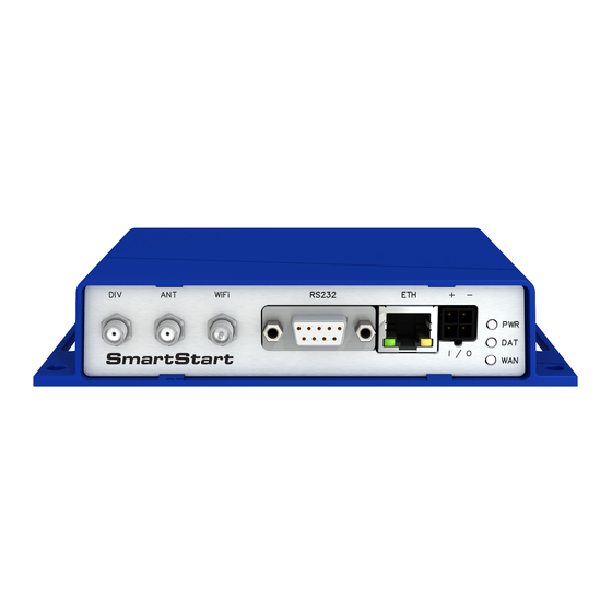
3. Router Design 3.1 Router Versions The SmartStart SL305 router is supplied in the following versions (see table below). All versions are available only in plastic casing. Router versions SL305 with RS232 SL305 with RS232 & WiFi Table 1: Router versions Figure 6: Front panel 3.2 Product Revisions... -
Page 13: Delivery Identification
LTE module Cat.4 EMEA, 1x ETH, 1x RS232, 1x BI, 1x BO, 2x SIM reader SmartStart SL305 BB-SL30510110 LTE module Cat.4 EMEA, 1x ETH, 1x RS232, 1x BI, 1x BO, 2x SIM reader, WiFi Table 4: Order codes overview SmartStart SL305 Hardware Manual... -
Page 14: Basic Dimensions Of The Router
3. Router Design 3.5 Basic Dimensions of the Router 3.5 Basic Dimensions of the Router 3.5.1 Front view Figure 8: Front view 3.5.2 Top view Figure 9: Top view 3.5.3 Bottom view 3.5.4 Rear view SmartStart SL305 Hardware Manual... - Page 15 3. Router Design 3.5 Basic Dimensions of the Router Figure 10: Bottom view Figure 11: Rear view SmartStart SL305 Hardware Manual...
-
Page 16: Mounting Recommendations
• To ensure the correct functioning of the router we recommend the use of an earth-bonding distribu- tion frame for the grounding of the power supply of the router, data cables and antenna within the switchboard. SmartStart SL305 Hardware Manual... -
Page 17: Removal From The Din Rail
To remove the router from the DIN rail, push the router down lightly, so the bottom part of the DIN rail clip (hitched to the DIN rail) gets out of the rail and then pull out the bottom part of the router away from the DIN rail. Figure 13: Removal from the DIN rail SmartStart SL305 Hardware Manual... -
Page 18: Description Of The Rear Panel
DB9 female Connector for serial interface RS232. Connector for main antenna. Connector for diversity antenna. WiFi R-SMA Connector for WiFi antenna (only for versions with WiFi module!). Table 5: Front panel description Figure 14: SmartStart front panel SmartStart SL305 Hardware Manual... - Page 19 Table 6: Status indication The status indication of the WAN LED is updated every 10 seconds. Or the difference between neighbouring cells is exactly 3 dBm. Or the difference between neighbouring cells is smaller than 3 dBm. SmartStart SL305 Hardware Manual...
- Page 20 The router is awakened after the power supply outage and subsequent renewal. Figure 16: Circuit example – connection of power supply The PWR / IO interface is also designed for the processing of binary input and control (setting) of binary output. SmartStart SL305 Hardware Manual...
- Page 21 Putting the router into LPM mode can be done using the lpm command, see Commands and Scripts application note for more details. Consumption in LPM mode may vary depending on the configuration of the router. SmartStart SL305 Hardware Manual...
- Page 22 SMA connector on the router’s front panel (see the figure below). Recommended tightening moment is 0.9 Nm. Figure 18: Connecting the antenna A diversity antenna improves the radio capability of the router at low signal strength. SmartStart SL305 Hardware Manual...
- Page 23 3.9.4 SIM Card Reader The SmartStart SL305 contains two readers for 3 V and 1.8 V SIM cards, which are located on the rear panel of the device. In order for the router to function, it is necessary to insert an activated SIM card with an unblocked PIN code.
- Page 24 Input/Output — — — — Table 9: Connection of Ethernet connector Figure 20: Ethernet connector The Ethernet cable plugs into the RJ45 connector labeled as ETH (see the figure below). Figure 21: Connection of Ethernet cable SmartStart SL305 Hardware Manual...
- Page 25 Receive Data Output Transmit Data Input Data Terminal Ready Input System Ground — Data Set Ready Output Request to Send Input Clear to Send Output Ring Indicator Table 10: Connection of RS232 connector Figure 22: RS232 connector SmartStart SL305 Hardware Manual...
- Page 26 Turns off and then turns on the router Disconnect and reconnect the power, press the Reboot button in the web configuration Reset Restores the default configuration and Press the RST button reboots the router Table 11: Description of router reset and restart SmartStart SL305 Hardware Manual...
-
Page 27: Connecting The Router Before The First Use
Don’t forget to insert a SIM card. The router can not operate without a connected antenna, SIM card and power supply. If the antenna is not connected, the router may be damaged. Figure 24: Router connection SmartStart SL305 Hardware Manual... - Page 28 WebAccess/DMP server. See the configuration manual [1], chapter Basic Information WebAccess/DMP Configuration, for more information. If the router’s label does not contain a unique password, use the password "root". SmartStart SL305 Hardware Manual...
- Page 29 Once the login information are entered successfully, the user will have access to the router’s web interface via the web browser. Figure 26: Router web interface A detailed description of the router settings in the Web interface can be found in the Configuration manual for SmartStart [1]. SmartStart SL305 Hardware Manual...
-
Page 30: Technical Parameters
2x SMA – 50 Ohm 1x R-SMA – 50 Ohm (only for WiFi) Table 12: Basic parameters Temperature range for routers equipped with WiFi module is reduced to -25 C to +55 C (-40 F to +131 F)! SmartStart SL305 Hardware Manual... -
Page 31: Technical Specification Of User Interfaces
EN 301 511, EN 301 908-1, EN 301 908-2, EN 301 908-13, EN 300 328 Safety EN 62368-1, EN IEC 62311 Transportation E-Mark E8 homologation number: 10R – 04 8634 Environmental REACH, RoHS and WEEE compliant Table 14: Standards and Regulations SmartStart SL305 Hardware Manual... -
Page 32: Type Tests And Environmental Conditions
3 axis, 8 hours per axis Shock EN 60068-2-27 ed. 2 half-sine, 15 g peak, 11 ms, 6 pulses per axis Isolation – Ethernet port 1.5 kV Table 15: Type tests and environmental conditions SmartStart SL305 Hardware Manual... -
Page 33: Technical Parameters Of Module
• VSWR – <2:1 (Antenna input impedance response as function of frequency. This shows the antenna resonances and its bandwidth). • SMA – 50 • For good diversity performance, the primary and secondary antennas should have different polariza- tions. SmartStart SL305 Hardware Manual... -
Page 34: Technical Parameters Of Wifi
Flash memory Available memory space 1 862 MB • 2x 256 MB – FW • 512 MB – User data storage • 838 MB – Space for Router Apps 512 MB Table 18: Other technical parameters SmartStart SL305 Hardware Manual... -
Page 35: Appendix A: Troubleshooting
Also enable "Send all remaining incoming packets to default server" feature and fill in the IP address of your Web server. On the Web server, the default gateway has to be the IP address of the router. DynDNS doesn’t work. • With private APN this will not work. SmartStart SL305 Hardware Manual... - Page 36 I switched the router to offline mode by SMS message, but the router is in online mode after reboot. • SMS messages do not change the router configuration. They remain in effect only until the router is rebooted. SmartStart SL305 Hardware Manual...
- Page 37 Web interface in "Configuration" section, "Services", "SSH". Then connect with any SSH client on port 22 of the router. User and password is the same as for the Web interface. Telnet on v2 routers can be enabled here: "Configuration" section, "Services", "Telnet". SmartStart SL305 Hardware Manual...
-
Page 38: Appendix B: Customer Support
+1-800-346-3119 (Monday – Friday, 7 a.m. to 5:30 p.m. CST) Fax: +1-815-433-5109 E-mail: support.iiot.ana@advantech.com Web: www.advantech.com Customer Support for Asia Phone: +886-2-2792-7818 #1299 (Monday – Friday, 9 a.m. to 5:30 p.m. UTC+8) Fax: +886-2-2794-7327 E-mail: icg.support@advantech.com.tw Web: www.advantech.com SmartStart SL305 Hardware Manual... -
Page 39: Appendix C: Regulatory & Safety Information
At the end of it’s life this pro- duct MUST NOT be mixed with other commercial waste for disposal. The device contains a battery. Remove the battery from the device before disposal. The battery in the device needs to be disposed of apart accordingly. Check the terms and conditions of your supplier for disposal information. SmartStart SL305 Hardware Manual... -
Page 40: Appendix D: Related Documents
Appendix D: Related Documents Configuration Manual for SmartStart Routers [EP] Product-related documents and applications can be obtained on Engineering Portal at https://icr.advantech.com/download address. SmartStart SL305 Hardware Manual... - Page 41 We, Advantech Czech s.r.o., declare that the radio equipment narrated in this user’s manual complies with Radio Equipment Regulations 2017 (S.I. 2017 No. 1206). We, Advantech Czech s.r.o., declare that the radio equipment narrated in this user’s manual complies with Directive 2014/53/EU.
Need help?
Do you have a question about the SmartStart SL305 and is the answer not in the manual?
Questions and answers