Advantech SmartMotion ST352 User Manual
Twin cellular module router
Hide thumbs
Also See for SmartMotion ST352:
- User manual (50 pages) ,
- Hardware manual (47 pages) ,
- Start manual (20 pages)

Subscribe to Our Youtube Channel
Related Manuals for Advantech SmartMotion ST352


Summary of Contents for Advantech SmartMotion ST352
- Page 1 Twin Cellular Module Router SmartMotion ST352 USER MANUAL LUCOM GmbH — Flößaustr. 22a — 90763 Fürth — Tel.: +49 911/ 957 606 00 — E-Mail: info@lucom.de — www.lucom.de...
- Page 2 Website www.advantech-bb.com c 2019 Advantech B+B SmartWorx s.r.o. No part of this publication may be reproduced or transmitted in any form or by any means, electronic or mechanical, including photography, recording, or any information storage and retrieval system without written consent. Information in this manual is subject to change without notice, and does not represent a commitment on the part of Advantech B+B SmartWorx.
- Page 3 Please see http://ep.advantech-bb.cz/devzone for more information. Advantech B+B SmartWorx s.r.o., Sokolska 71, 562 04 Usti nad Orlici, Czech Republic Document No. MAN-0011-EN, revision from April 12, 2019. Released in the Czech Republic. LUCOM GmbH — Flößaustr. 22a — 90763 Fürth — Tel.: +49 911/ 957 606 00 — E-Mail: info@lucom.de — www.lucom.de...
-
Page 4: Table Of Contents
SmartMotion ST352 Contents 1 Safety Instructions 2 WEEE directive 3 Router Description 3.1 Usage of the Router ....... . . - Page 5 SmartMotion ST352 7.3 Type tests and environmental conditions ..... . 7.4 Technical parameters of both of cellular modules ....
- Page 6 SmartMotion ST352 List of Figures Access to the Internet from LAN ......Backed up access to the Internet .
- Page 7 SmartMotion ST352 List of Tables Router versions ........
- Page 8 SmartMotion ST352 1. Safety Instructions Please, observe the following instructions: The router must be used in compliance with all applicable international and national laws and in compliance with any special restrictions regulating the utilization of the router in prescribed applications and environments.
-
Page 9: Weee Directive
SmartMotion ST352 2. Product Disposal Instructions The WEEE (Waste Electrical and Electronic Equipment: 2012/19/EU) directive was in- troduced to ensure that electrical/electronic products are recycled using the best available recovery techniques in order to minimize impact on the environment. This product contains high quality materials and components which can be recycled. -
Page 10: Router Description
SmartMotion ST352 3. Router Description SmartMotion ST352 is an industrial cellular router intended for wireless communication in mobile networks that make use of LTE, HSPA+, UMTS, CDMA, EDGE or GPRS technology. The router is equipped with two independent cellular modules for backed up communication. -
Page 11: Usage Of The Router
SmartMotion ST352 Examples of possible applications mobile office telemetric fleet management remote monitoring security system vending and dispatcher machines telematic 3.1 Usage of the Router The router is primarily intended for these four basic situations: I. Access to the Internet from LAN Figure 1: Access to the Internet from LAN LUCOM GmbH —... -
Page 12: Backed Up Access To The Internet
SmartMotion ST352 II. Backed up access to the Internet (from LAN) Figure 2: Backed up access to the Internet III. Secure networks interconnection or using VPN Figure 3: Using VPN tunnel LUCOM GmbH — Flößaustr. 22a — 90763 Fürth — Tel.: +49 911/ 957 606 00 — E-Mail: info@lucom.de — www.lucom.de... -
Page 13: Serial Gateway
SmartMotion ST352 IV. Serial Gateway Figure 4: Serial Gateway LUCOM GmbH — Flößaustr. 22a — 90763 Fürth — Tel.: +49 911/ 957 606 00 — E-Mail: info@lucom.de — www.lucom.de... -
Page 14: Contents Of Package
SmartMotion ST352 4. Contents of Package Basic delivered set of router includes: Router, Power supply, Crossover UTP cable, Up to five external antennas, – 4x Terminal antenna for standard LTE – 1x WiFi antenna (if router contains WiFi module) Loose power and I/O connector (+8 pins Clip for the DIN rail, Paper start guide. -
Page 15: Router Design
5. Router Design 5.1 Router versions SmartMotion ST352 router is supplied in the following versions (see table below). All ver- sions are available in a metal box. All versions are available with PoE PD (Power over Ethernet – powered device) so you can power the router from both ETH0 and ETH1 interfaces, or with PoE PSE (power source equipment) so you can power other devices by the router. -
Page 16: Order Codes
SmartMotion ST352 5.3 Order codes Order codes overview is shown in the table below. Product Name Order code Features – interfaces ST352 BB-ST3520x0yz 2x LTE module, 2x ETH, 1x USB, 2x BI, 1x BO, 1x microSD reader, 4x SIM reader... -
Page 17: Examples Of Order Code
SmartMotion ST352 Examples of complete order code: Order code Features – interfaces Power supply BB-ST35208020 2x LTE module, 2x ETH, 1x USB, 2x BI, 1x metal none BO, 1x microSD reader, 4x SIM reader, PoE BB-ST35219020 2x LTE module, 2x ETH, 1x USB, 2x BI, 1x... -
Page 18: Basic Dimensions Of The Router Box
SmartMotion ST352 5.4 Basic dimensions of the router box Figure 9: Basic dimensions of the router box 5.5 Mounting recommendations Possibility to be put on a work surface, DIN rail EN 60715 with included metal clip. For the most of applications with a built-in router in a switch board it is possible to recognize... -
Page 19: Removal From The Din Rail
SmartMotion ST352 – Length of the bunch (combination of power supply and data cables) can be maxi- mum 1.5 m. If the length of data cables exceeds 1.5 m or in the event of, the cable leads towards the switch – board. We recommend installing over – voltage protec- tors (surge suppressors). -
Page 20: Description Of The Rear Panel
SmartMotion ST352 5.7 Description of the rear panel The rear panel contains only four SIM cards readers (SIM1, SIM2, SIM3 and SIM4), mi- croSD card reader (SD) and RST button used to restore default configuration and reboot the SmartMotion router. -
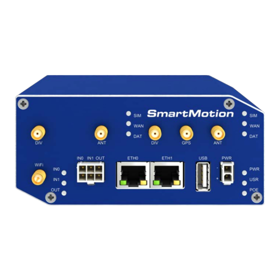
Page 21: Status Indication
SmartMotion ST352 5.8.1 Status indication There are nine LED indicators on the front panel to provide router status information. Each ETH port has two additional LEDs that provide information about the port status. Caption Color State Description Green Blinking Router is ready. -
Page 22: Power Connector Pwr
SmartMotion ST352 5.8.2 Power connector PWR Panel socket 2-pin. Pin number Signal mark Description GND(-) Negative pole of DC supply voltage VCC(+) Positive pole of DC supply voltage (+10 to +60 V DC) Table 10: Connection of power connector Figure 13: Power connector Unit has to be supplied by a power supply specified as a Limited Power Source (LPS) ac-... -
Page 23: Antenna Connector Ant, Div, Gps And Wifi
SmartMotion ST352 5.8.3 Antenna connector ANT, DIV, GPS and WiFi Main, diversity and GPS antennas are connected to the router using the SMA connector on the front panel. There is also available R-SMA antenna connector through which the additional antenna can be connected, if the router is equipped with WiFi module. -
Page 24: Sim Card Reader
SmartMotion ST352 5.8.4 SIM card reader Four SIM card readers for 3 V and 1.8 V SIM cards are placed on the rear panel of the router. For getting the router to work is necessary to insert an activated SIM card with an un- blocked PIN code. -
Page 25: Microsd Card Reader
SmartMotion ST352 5.8.5 MicroSD card reader The microSD card reader is located on the rear panel of the router (the third slot). This card reader allows the router to operate with microSD memory cards. The technical specifications are stated in the table below. -
Page 26: Ethernet Ports (Eth0 And Eth1)
SmartMotion ST352 5.8.6 Ethernet Ports (ETH0 and ETH1) Panel socket RJ45. Signal mark Description Data flow direction TXD+ Transmit Data – positive pole Input/Output TXD- Transmit Data – negative pole Input/Output RXD+ Receive Data – positive pole Input/Output PoE power + (if it’s equipped by PoE) PoE power + (if it’s equipped by PoE) -
Page 27: Power Over Ethernet (Poe)
SmartMotion ST352 5.8.7 Power over Ethernet (PoE) On the router models with PoE, the PoE+ standard IEEE 802.3at-2009 and PoE standard IEEE 802.3af-2003 are supported in both Ethernet ports (ETH0, ETH1). The PoE PD version allows the router to be powered over the Ethernet by another PoE PSE device. The PoE PSE version also allows the router to power other devices over the Ethernet. -
Page 28: Poe Pse Usage
SmartMotion ST352 PoE PSE Figure 21: PoE PSE usage The power supply used with the PoE PSE router has to provide voltage from 44 to 57 V DC and the output power has to be at least 65 W for full PoE+ use (Class 4) in both Ethernet ports (ETH0 and ETH1). -
Page 29: Usb Port
SmartMotion ST352 5.8.8 USB Port Panel socket USB-A. Signal mark Description Data flow direction +5 V Positive pole of 5 V DC supply voltage, 0.5 A USB data - USB data signal – negative pole Input/Output USB data + USB data signal – positive pole... -
Page 30: I/O Port
SmartMotion ST352 5.8.9 I/O Port Panel socket 6-pin. Signal mark Description Binary input 0 Binary input 0 Binary input 1 Binary input 1 Binary output Binary output Table 15: Connection of I/O port Figure 23: I/O connector The I/O user Interface is designed for the processing of binary input and control (setting) of binary output. -
Page 31: Binary Inputs Connection
SmartMotion ST352 Binary inputs connection example: Figure 24: Binary inputs connection Binary output Binary output parameters: – 60 V AC / 300 mA – 60 V DC / 300 mA The current of the binary output is limited by a resettable fuse (300 mA). -
Page 32: Reset
SmartMotion ST352 5.8.10 Reset When the PWR LED starts flashing on the front panel, it is possible to restore the de- fault configuration of the router by pressing the RST button on the rear panel. After pressing this button the default configuration will be restored and the router will reboot (after which the green LED will be on). -
Page 33: First Use
SmartMotion ST352 6. First Use 6.1 Connecting the router before first use Before putting the router into operation it is necessary to connect all components which are required to run your applications. Don’t forget to insert SIM card. The router can not operate without connected antenna, SIM card and power supply. If the antenna is not connected, router can be damaged. -
Page 34: Start
SmartMotion ST352 6.2 Start The router is put into operation when the power supply is connected to this router. By default, the router will automatically start to log on to the default APN. DHCP server will start to assign addresses for devices on the Ethernet port ETH0. Router behavior can be changed via the web interface. -
Page 35: Router Web Interface
SmartMotion ST352 After successfully entering login information user gains access to the router via his internet browser. Figure 30: Router web interface A detailed description of the router settings via the Web interface can be found in the document Configuration manual for SmartMotion routers. -
Page 36: Technical Parameters
SmartMotion ST352 7. Technical Parameters 7.1 Basic parameters SmartMotion Router Temperature range Operating -40 C to +75 C Storage -40 C to +85 C Cold start -35 C Data transfers via mobile network are available immediately -40 C Data transfers via mobile network are available approximately in five minutes after the start of... -
Page 37: Standards And Regulations
SmartMotion ST352 7.2 Standards and regulations The router complies with the following standards and regulations. Standards and regulations Telecom and emission ETSI EN 301 511 V12.5.1, ETSI EN 300 440 V2.1.1, ETSI EN for the 1st module 301 908-1 V11.1.1, ETSI EN 301 908-2 V11.1.1, ETSI EN 301 908-13 V11.1.1... -
Page 38: Type Tests And Environmental Conditions
SmartMotion ST352 7.3 Type tests and environmental conditions Phenomena Test Description Test levels EN 61000-4-2 Enclosure contact 6 kV (crit. A) Enclosure air 8 kV (crit. A) RF field AM EN 61000-4-3 Enclosure 20 V/m (crit. A) modulated (80 – 2700 MHz) 3 V/m (crit. -
Page 39: Technical Parameters Of Both Of Cellular Modules
SmartMotion ST352 7.4 Technical parameters of both of cellular modules Technical parameters of both of cellular modules LTE parameters Bit rate 100 Mbps (DL) / 50 Mbps (UL) 3GPP rel. 8 standard Supported bandwidths: 5 MHz, 10 MHz, 20 MHz... -
Page 40: Technical Parameters Of Gps
SmartMotion ST352 7.5 Technical parameters of GPS GPS specifications Antenna SMA 50 – active Protocols NMEA 0183 v3.0 Frequency 1575.42 MHz Sensitivity Tracking: -161 dBm Acquisition (Assisted): -158 dBm Acquisition (Standalone): -145 dBm Acquisition time Hot start: 1 s Warm start: 29 s... -
Page 41: Technical Parameters Of Wifi
SmartMotion ST352 7.6 Technical parameters of WiFi WiFi Antenna connector R-SMA – 50 Supported WiFi band 2.4 GHz, 5 Ghz Standards 802.11a, 802.11b, 802.11g, 802.11n 2.4 GHz supported channels 1, 2, 3, 4, 5, 6, 7, 8, 9, 10, 11, 12, 13... -
Page 42: Technical Parameters Of Power Over Ethernet (Poe)
SmartMotion ST352 7.8 Technical Parameters of Power over Ethernet (PoE) Standards IEEE 802.3at-2009 (PoE+) and IEEE 802.3af-2003 (PoE) are supported. Ca- bling needed is Category 5, up to 12.5 . It is possible to use a passive PoE injector. PoE PD: parameters for opposite PSE Input voltage range 42.5 –... -
Page 43: Recommended Literature
SmartMotion ST352 8. Recommended Literature Advantech B+B SmartWorx: Start Guide for SmartMotion, Advantech B+B SmartWorx: Configuration Manual for SmartMotion Routers, Advantech B+B SmartWorx: Commands and Scripts for v2 and v3 Routers. LUCOM GmbH — Flößaustr. 22a — 90763 Fürth — Tel.: +49 911/ 957 606 00 — E-Mail: info@lucom.de — www.lucom.de... -
Page 44: Troubleshooting
9. Troubleshooting If you cannot connect to the router from your PC, your network card may be configured in such a way that it is not possible to connect to the router. Take one or more of the following steps in order to solve the problem: Make sure your PC’s network card is configured to obtain the IP address form the DHCP server (by default the DHCP server is running in the router). - Page 45 In a private APN it is not recommended to get the DNS settings from operator (on "Mobile WAN" page) Go to "System Log" page in "Status" section and observe where the error occurs. I cannot connect from the Internet to the device behind the router. I have NAT enabled.
- Page 46 Serial communication is not working. Verify that the router model supports serial communications. Also verify the serial communication settings. To do so, open the router’s configuration menu via the web browser, select the appropriate "Expansion Port" from "Configuration" part of the menu and verify the settings.
-
Page 47: Customers Support
During cleaning of the router do not use aggressive chemicals, solvents and abrasive cleaners! Hereby, Advantech B+B SmartWorx s.r.o. company declares that the radio equipment narrated in this user’s guide is in compliance with EU Directive 2014/53/EU. The full text of the EU Declaration of Conformity is available at the following internet address: www.advantech-bb.cz/eudoc...
Need help?
Do you have a question about the SmartMotion ST352 and is the answer not in the manual?
Questions and answers