Advantech SmartFlex SR306 User Manual
Lte industrial router
Hide thumbs
Also See for SmartFlex SR306:
- Start manual (20 pages) ,
- Start manual (20 pages) ,
- Start manual (20 pages)
Table of Contents
Advertisement
Quick Links
Advertisement
Table of Contents

Subscribe to Our Youtube Channel
Related Manuals for Advantech SmartFlex SR306


Summary of Contents for Advantech SmartFlex SR306
- Page 1 LTE Industrial Router SmartFlex SR306 USER MANUAL...
- Page 2 SmartFlex SR306 © 2023 Advantech Czech s.r.o. No part of this publication may be reproduced or transmitted in any form or by any means, electronic or mechanical, including photography, recording, or any information storage and retrieval system without written consent. Information in this manual is subject to change without notice, and does not represent a commitment on the part of Advantech.
- Page 3 Information, notice – Useful tips or information of special interest. GPL license https://icr.advantech.cz/source-code Source codes under GPL license are available at address. Advantech Czech s.r.o., Sokolska 71, 562 04 Usti nad Orlici, Czech Republic Document No. MAN-0007-EN, revision from June 8, 2023. Released in the Czech Republic.
-
Page 4: Table Of Contents
SmartFlex SR306 Contents 1 Safety Instructions 2 WEEE directive 3 Router Description 3.1 Usage of the Router ....... . . - Page 5 SmartFlex SR306 7 Technical Parameters 7.1 Basic parameters ........
- Page 6 SmartFlex SR306 List of Figures Access to the Internet from LAN ......Backed up access to the Internet .
- Page 7 SmartFlex SR306 Version with RS232-RS485/422 interface ..... RS232 connector ........
- Page 8 SmartFlex SR306 List of Tables Router versions ........
-
Page 9: Safety Instructions
SmartFlex SR306 1. Safety Instructions Please, observe the following instructions: • The router must be used in compliance with all applicable international and national laws and in compliance with any special restrictions regulating the utilization of the router in prescribed applications and environments. -
Page 10: Weee Directive
SmartFlex SR306 2. Product Disposal Instructions The WEEE (Waste Electrical and Electronic Equipment: 2012/19/EU) directive was in- troduced to ensure that electrical/electronic products are recycled using the best available recovery techniques to minimize the environmental impact. This product contains high quality materials and components which can be recycled. -
Page 11: Router Description
SmartFlex SR306 3. Router Description SmartFlex SR306 is an industrial cellular router intended for the Latin American (LATAM) and Asia Pacific (APAC) markets. However, it can also be operated in Europe, Middle East and Africa (EMEA) area. This router is an ideal device for wireless communication in mobile networks that make use of LTE, HSPA+, UMTS, EDGE or GPRS technology. -
Page 12: Usage Of The Router
SmartFlex SR306 Examples of possible applications • mobile office • telemetric • fleet management • remote monitoring • security system • vending and dispatcher machines • telematic 3.1 Usage of the Router The router is primarily intended for these four basic situations: I. -
Page 13: Backed Up Access To The Internet
SmartFlex SR306 II. Backed up access to the Internet (from LAN) Figure 2: Backed up access to the Internet III. Secure networks interconnection or using VPN Figure 3: Using VPN tunnel... -
Page 14: Serial Gateway
SmartFlex SR306 IV. Serial Gateway Figure 4: Serial Gateway... -
Page 15: Contents Of Package
SmartFlex SR306 4. Contents of Package Basic delivered set of router includes: • router, • power supply (based on ordered plug type), • crossover UTP cable, • up to three external antennas, • loose power and I/O connector (+8 pins •... -
Page 16: Router Design
Check with your local Advantech sales representative for available options and HW configura- tions. SmartFlex SR306 router is supplied in the following versions (see table below). All versions are available in plastic or metal box according to customer requirements. All versions are available with PoE PD (Power over Ethernet –... -
Page 17: Version Switch (Plastic)
SmartFlex SR306 Figure 10: Version SWITCH (plastic) Figure 14: Version SWITCH (metal) Figure 11: Version SWITCH and WiFi (plastic) Figure 15: Version SWITCH and WiFi (metal) Figure 12: Version RS232-RS485 (plastic) Figure 16: Version RS232-RS485 (metal) Figure 13: Ver. RS232-RS485 & WiFi (plastic) -
Page 18: Version Rs232-Rs485-Eth (Plastic)
SmartFlex SR306 Figure 18: Version RS232-RS485-ETH (plastic) Figure 20: Version RS232-RS485-ETH (metal) Figure 19: RS232-RS485-ETH & WiFi (plastic) Figure 21: RS232-RS485-ETH & WiFi (metal) -
Page 19: Product Revisions
SmartFlex SR306 5.2 Product Revisions For the product revision history, see the table below. The revision number is printed on the packaging and product labels. The router GUI can also display the product revision under Status -> General -> System Information ->... -
Page 20: Order Codes
SmartFlex SR306 5.4 Order codes Order codes overview is shown in the table below. Product Name Order code Features – interfaces SR306 BB-SR3060x0yz LTE module, 2x ETH, 1x USB, 2x BI, 1x BO, 1x mi- croSD reader, 2x SIM reader... -
Page 21: Type Of Router Box
SmartFlex SR306 Letter "y" – type of the router box Type of box Number "y" in code Plastic Metal Table 6: Type of router box Letter "z" – type of power supply plug Plug type Number "z" in code Without accessories... -
Page 22: Basic Dimensions Of The Router Box
SmartFlex SR306 5.5 Basic dimensions of the router box Figure 23: Basic dimensions of the router box 5.6 Mounting Recommendations • It is possible to place the router on a flat surface, • DIN rail EN 60715 with the included plastic or metal clip. -
Page 23: Removal From The Din Rail
SmartFlex SR306 – Data cables must not have a reticular tension of 230 V/50 Hz or 120 V/60 Hz. • Sufficient space must be left between each connector for the handling of cables, • To ensure the correct functioning of the router we recommend the use of an earth- bonding distribution frame for the grounding of the power supply of the router, data cables and antenna within the switchboard. -
Page 24: Description Of The Rear Panel
SmartFlex SR306 5.8 Description of the rear panel The rear panel contains two holders for SIM cards (SIM1 and SIM2), a holder for microSD card (SD) and an RST button used to restore the default configuration and reboot the router. -
Page 25: Status Indication
SmartFlex SR306 5.9.1 Status indication There are status LEDs on the front panel to provide router status information. Each ETH port has two additional LEDs that provide information about the port status. Caption Color State Description Green Blinking The router is booting up. -
Page 26: Power Connector Pwr
SmartFlex SR306 5.9.2 Power connector PWR Panel socket 2-pin. Pin number Signal mark Description GND(-) Negative pole of DC supply voltage VCC(+) Positive pole of DC supply voltage (+10 to +60 V DC) Table 11: Connection of power connector Figure 27: Power connector Unit has to be supplied by a power supply specified as a Limited Power Source (LPS) ac- cording to Annex Q of IEC 62368-1. - Page 27 SmartFlex SR306 Low Power Mode In applications requiring low power consumption (such as solar power - not 7/24 mode) is strictly recommended to use LPM mode prior to powering down the entire router. LPM (Low Power Mode) is a router mode where the router is in sleep mode with minimal power consumption.
-
Page 28: Antenna Connector Ant, Div, Gps And Wifi
SmartFlex SR306 5.9.3 Antenna connector ANT, DIV, GPS and WiFi The main, diversity and GPS antennas are connected to the router using the SMA connec- tor on the front panel. There is also an R-SMA antenna connector available, through which an additional antenna can be connected, if the router is equipped with a WiFi module. -
Page 29: Sim Card Reader
SmartFlex SR306 5.9.4 SIM card reader Two SIM card readers for 3 V and 1.8 V SIM cards are located on the rear panel of the router. In order for the router to function, it is necessary to insert an activated SIM card with an unblocked PIN code. -
Page 30: Microsd Card Reader
SmartFlex SR306 5.9.5 MicroSD card reader The microSD card reader is located on the router’s rear panel (the third slot). This card reader allows the router to operate with microSD memory cards. The technical specifications are stated in the table below. The microSD card changing procedure is described below. - Page 31 SmartFlex SR306 • To mount the card to to mnt directory, use the mount command: mount /dev/mmcblk0p1 /mnt For more information about the commands for creating, mounting, checking and unmounting a file system on a microSD card, see the application note for Ext4_tools router app.
-
Page 32: Ethernet Ports (Eth0 And Eth1)
SmartFlex SR306 5.9.6 Ethernet Ports (ETH0 and ETH1) The panel socket RJ45 is used for this interface. The isolation barrier of the Ethernet signal ports against the ground is 1500 V. 10base-T & 100base-T PoE (Mode B) Tx+ (Transmit Data+) —... -
Page 33: Power Over Ethernet (Poe)
SmartFlex SR306 5.9.7 Power over Ethernet (PoE) Available only for models with PoE feature; see Chapter for the order codes. You can not power the router via the ETH2 ports on the SWITCH router version. The PoE PD is available on the ETH0 and ETH1 ports only. -
Page 34: Poe Pse Usage
SmartFlex SR306 PoE PSE Figure 35: PoE PSE usage The power supply used with the PoE PSE router has to provide voltage from 44 to 57 V DC and the output power has to be at least 65 W for full PoE+ use (Class 4) in both Ethernet ports (ETH0 and ETH1). -
Page 35: Usb Port
SmartFlex SR306 5.9.8 USB Port Panel socket USB-A. Signal mark Description Data flow direction +5 V Positive pole of 5 V DC supply voltage, 0.5 A USB data - USB data signal – negative pole Input/Output USB data + USB data signal – positive pole... -
Page 36: I/O Port
SmartFlex SR306 5.9.9 I/O Port Panel socket 6-pin. Signal mark Description Binary input 0 Binary input 0 Binary input 1 Binary input 1 Binary output Binary output Table 16: Connection of I/O port Figure 37: I/O connector The I/O user Interface is designed for the processing of binary input and control (setting) of binary output. -
Page 37: Binary Connection
SmartFlex SR306 Binary output • Binary output parameters: – 60 V AC / 300 mA – 60 V DC / 300 mA • The current of the binary output is limited by a resettable fuse (300 mA). Binary inputs and output connections... -
Page 38: Reset
SmartFlex SR306 5.9.10 Reset When the PWR LED starts flashing on the front panel, it is possible to restore the de- fault configuration of the router by pressing the RST button on the rear panel. After pressing this button the default configuration will be restored and the router will reboot (after which the green LED will be on). -
Page 39: Interfaces Description
SmartFlex SR306 5.10 Interfaces Description Besides the basic version of SmartFlex router there are available versions with one of the following interfaces: • SWITCH interface • RS232-RS485/422 interface • RS232-RS485-ETH interface 5.10.1 SWITCH interface The three LAN ports of the SWITCH interface for SmartFlex routers (RJ45 connectors for connecting Ethernet devices) act as a typical switch device. -
Page 40: Switch Interface Parameters
SmartFlex SR306 Technical specification of Ethernet IEEE 802.3: Ethernet interface, IEEE 802.3 standard Maximum data rate 100 Mbps Max. total cable length (300 Bd, 200 nF/km) 100 m Table 20: SWITCH interface parameters... -
Page 41: Rs232-Rs485/422 Interface
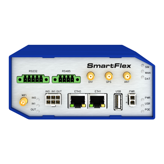
SmartFlex SR306 5.10.2 RS232-RS485/422 interface These interfaces are physically connected through the 5-pin and 4-pin terminal block con- nectors. The insulation strength is up to 2.5 kV. Attention, connectors are not isolated from each other! No state indication is displayed for this interface. These router versions comply with the standards and temperature ranges stated in Chap. -
Page 42: Rs485/422 Connector
SmartFlex SR306 Connection of RS485 connector: Signal Description Direction TxRx+ RS485 B (+) Input/Output TxRx- RS485 A (-) Input/Output TxRx+ RS485 B (+) Input/Output TxRx- RS485 A (-) Input/Output Table 22: Connection of RS485 connector Connection of RS422 connector: Signal... -
Page 43: Connection Of Jumpers
SmartFlex SR306 Figure 44: Connection of jumpers Technical specification of RS232 and RS485 bus: RS232 and RS485 interface Max. operating RS232 bus current 15 mA Max. number of devices on RS485 bus Max. output current on RS485 bus 60 mA Max. -
Page 44: Rs232-Rs485-Eth Interface
SmartFlex SR306 5.10.3 RS232-RS485-ETH interface This interface board includes a panel RJ45 connector for Ethernet connection (ETH2 in the figure), and four-pin and three-pin terminal block connectors for RS232 and RS485 con- nection. The insulation strength is up to 2.5 kV between the ETH2 and RS485 interfaces and from the rest of the router, too. -
Page 45: Rs485 Connector
SmartFlex SR306 When connecting counterpart terminal block connectors (included in package with the router), use cables with nominal cross section 0.2 to 1.0 square mm (30 to 16 AWG). Recommended stripping length is 5 mm. For M2 captive screws the screw driver 0.5 x 3 mm is recommended. -
Page 46: State Indication Of The Rs232-Rs485-Eth Interface
SmartFlex SR306 State indication of the interface: Description of indication ETH2 – green LED Selected 100 Mbps Selected 10 Mbps ETH2 – Yellow LED The network cable is connected Blinking Data transmission The network cable is not connected RS485, RS232 – green LED Indicates Receive data RS485, RS232 –... -
Page 47: First Use
SmartFlex SR306 6. First Use 6.1 Connecting the router before first use Before putting the router into operation it is necessary to connect all of the components that are required to run your applications. Don’t forget to insert a SIM card. -
Page 48: Start
SmartFlex SR306 6.2 Start The router will start when a power supply is connected to the router. By default, the router will automatically start to log on to the default APN. The DHCP server will start to assign addresses for devices connected through the Ethernet port ETH0. Router’s behavior can be changed via the web interface. -
Page 49: Entering Login Information
SmartFlex SR306 Figure 51: Entering login information Figure 52: Router web interface A detailed description of the router settings in the Web interface can be found in the Configuration manual for SmartFlex routers. -
Page 50: Technical Parameters
SmartFlex SR306 7. Technical Parameters 7.1 Basic parameters SmartFlex Router Temperature range Operating -40 C to +75 C (-40 F to +167 F) Storage -40 C to +85 C (-40 F to +185 F) Cold start -35 C Data transfers via mobile network are available... -
Page 51: Standards And Regulations
SmartFlex SR306 7.2 Standards and regulations The router complies with the following standards and regulations. Parameter Description Radio ETSI EN 301 511, ETSI EN 301 908-2, ETSI EN 301 908-13, ETSI EN 300 328, ETSI EN 301 893 ETSI EN 301 489-1, ETSI EN 301 489-1, ETSI EN 301 489-17... -
Page 52: Type Tests And Environmental Conditions
SmartFlex SR306 7.3 Type tests and environmental conditions Phenomena Test Description Test levels EN 61000-4-2 Enclosure contact 6 kV (crit. A) Enclosure air 8 kV (crit. A) RF field AM EN 61000-4-3 Enclosure 20 V/m (crit. A) modulated (80 – 2700 MHz) 3 V/m (crit. -
Page 53: Technical Parameters Of Cellular Module
SmartFlex SR306 7.4 Technical parameters of cellular module Technical parameters of cellular module LTE parameters Bit rate 100 Mbps (DL) / 50 Mbps (UL) UE CAT. 3 3GPP rel. 9 standard Supported bandwidths: 5 Mhz, 10 Mhz, 20 Mhz Supported frequencies: B20 (800 MHz), B8 (900 MHz),... -
Page 54: Technical Parameters Of Gps
SmartFlex SR306 7.5 Technical parameters of GPS GPS specifications Antenna SMA 50 – active Protocols NMEA 0183 v3.0 Frequency 1575.42 MHz Sensitivity Tracking: -161 dBm Acquisition (Assisted): -158 dBm Acquisition (Standalone): -145 dBm Acquisition time Hot start: 1 s Warm start: 29 s... -
Page 55: Technical Parameters Of Wifi
SmartFlex SR306 7.6 Technical parameters of WiFi WiFi Antenna connector R-SMA – 50 Supported WiFi band 2.4 GHz, 5 Ghz Standards 802.11a, 802.11b, 802.11g, 802.11n 2.4 GHz supported channels 1, 2, 3, 4, 5, 6, 7, 8, 9, 10, 11, 12, 13... -
Page 56: Technical Parameters Of Power Over Ethernet (Poe)
SmartFlex SR306 7.8 Technical Parameters of Power over Ethernet (PoE) Standards IEEE 802.3at-2009 (PoE+) and IEEE 802.3af-2003 (PoE) are supported. Ca- bling needed is Category 5, up to 12.5 . It is possible to use a passive PoE injector. PoE PD: parameters for opposite PSE Input voltage range 42.5 –... -
Page 57: Related Documents
SmartFlex SR306 8. Related Documents Advantech Czech: Start Guide, Advantech Czech: Configuration Manual for SmartFlex Routers. -
Page 58: Troubleshooting
SmartFlex SR306 9. Troubleshooting If you cannot connect to the router from your PC, your network card may be configured in such a way that it is not possible to connect to the router. Take one or more of the following steps in order to solve the problem: •... - Page 59 SmartFlex SR306 I cannot connect from the Internet to the device behind the router. I have NAT enabled. • The device’s gateway has to be configured so it points to the router. I can’t access my Web server placed behind the router over NAT.
- Page 60 SmartFlex SR306 Serial communication is not working. • Verify that the router model supports serial communications. Also verify the serial communication settings. To do so, open the router’s configuration menu via the web browser, select the appropriate "Expansion Port" from "Configuration" part of the menu and verify the settings.
-
Page 61: Customer Support
SmartFlex SR306 10. Customer Support Customer Support for Europe Advantech Czech s.r.o. Sokolska 71 562 04, Usti nad Orlici, Czech Republic Phone: +353 91 792444 Fax: +353 91 792445 E-mail: iiotcustomerservice@advantech.eu Web: www.advantech.com Customer Support for NAM Advantech B+B SmartWorx... - Page 62 SmartFlex SR306 We, Advantech Czech s.r.o., declare that the radio equipment narrated in this user’s manual complies with Directive 2014/53/EU. The full text of the EU Declaration of Conformity is available at the following internet address: icr.advantech.cz/eudoc...
Need help?
Do you have a question about the SmartFlex SR306 and is the answer not in the manual?
Questions and answers