Advantech SmartStart SL305 User Manual
Hide thumbs
Also See for SmartStart SL305:
- User manual (44 pages) ,
- Hardware manual (42 pages) ,
- Start manual (20 pages)
Table of Contents
Advertisement
Quick Links
Advertisement
Table of Contents

Subscribe to Our Youtube Channel
Related Manuals for Advantech SmartStart SL305


Summary of Contents for Advantech SmartStart SL305
- Page 1 LTE Industrial Router SmartStart SL305 USER MANUAL...
- Page 2 SmartStart SL305 c 2022 Advantech Czech s.r.o. No part of this publication may be reproduced or transmitted in any form or by any means, electronic or mechanical, including photography, recording, or any information storage and retrieval system without written consent. Information in this manual is subject to change without notice, and does not represent a commitment on the part of Advantech.
- Page 3 Information, notice – Useful tips or information of special interest. GPL licence Source codes under GPL licence are available at https://icr.advantech.cz/source-code address. Advantech Czech s.r.o., Sokolska 71, 562 04 Usti nad Orlici, Czech Republic Document No. MAN-0056-EN, revision from March 3, 2022. Released in the Czech Republic.
-
Page 4: Table Of Contents
SmartStart SL305 Contents 1 Safety Instructions 2 WEEE directive 3 Router Description 3.1 LTE Category 4 (Cat.4) ....... - Page 5 SmartStart SL305 7 Technical Parameters 7.1 Basic Parameters ........
- Page 6 SmartStart SL305 List of Figures Access to the Internet from LAN ......Backed up access to the Internet .
- Page 7 SmartStart SL305 List of Tables Router versions ........
-
Page 8: Safety Instructions
SmartStart SL305 1. Safety Instructions Please, observe the following instructions: The router must be used in compliance with all applicable international and national laws and in compliance with any special restrictions regulating the utilization of the router in prescribed applications and environments. -
Page 9: Weee Directive
SmartStart SL305 2. Product Disposal Instructions The WEEE (Waste Electrical and Electronic Equipment: 2012/19/EU) directive was in- troduced to ensure that electrical/electronic products are recycled using the best available recovery techniques to minimize the impact on the environment. This product contains high quality materials and components which can be recycled. -
Page 10: Router Description
SmartStart SL305 3. Router Description Cellular router SmartStart is designed for wireless communication in the mobile networks that make use of traditional cellular technologies. The primary purpose of this router is its use in the newest Category 4 (Cat.4) services on the cellular LTE network. -
Page 11: Usage Of The Router
SmartStart SL305 The router also supports additional software like R-SeeNet for permanent traffic monitoring of routers or WebAccess/VPN for remote access. Examples of possible applications mobile office telematic smart meters for utilities telemetric fleet management remote monitoring security systems vending and dispatcher machines 3.4 Usage of the Router... -
Page 12: Backed Up Access To The Internet
SmartStart SL305 II. Backed up access to the Internet (from LAN) Figure 2: Backed up access to the Internet III. Secure networks interconnection or using VPN Figure 3: Using a VPN tunnel... -
Page 13: Serial Gateway
SmartStart SL305 IV. Serial Gateway Figure 4: Serial Gateway... -
Page 14: Contents Of Package
SmartStart SL305 4. Contents of Package The basic router set available for delivery includes the following items: router, power and IO cable (1.5 m long), clip for the DIN rail (two screws are included), paper start guide. Figure 5: Contents of package... -
Page 15: Router Design
SmartStart SL305 5. Router Design 5.1 Router Versions The SmartStart SL305 router is supplied in the following versions (see table below). All versions are available only in plastic casing. Router versions SL305 with RS232 SL305 with RS232 & WiFi Table 1: Router versions... -
Page 16: Delivery Identification
SmartStart SL305 5.2 Delivery Identification Trade name Product name Description SL305 SmartStart LTE router (Cat.4) for EMEA Table 2: Delivery identification Figure 7: Product label 5.3 Order Codes The table below shows an overview of order codes. Name Order code Features –... -
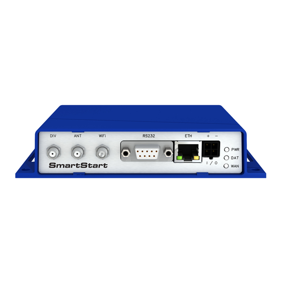
Page 17: Basic Dimensions Of The Router
SmartStart SL305 5.4 Basic Dimensions of the Router 5.4.1 Front view Figure 8: Front view 5.4.2 Top view Figure 9: Top view... -
Page 18: Bottom View
SmartStart SL305 5.4.3 Bottom view Figure 10: Bottom view 5.4.4 Rear view Figure 11: Rear view... -
Page 19: Mounting Recommendations
SmartStart SL305 5.5 Mounting recommendations It is possible to place the router on a flat surface, mount the router on a wall using four holes in corners (Figure 10) and screws with diam- eter 4 mm, attach the router on DIN rail EN 60715 with the included clip BB-SBD25. -
Page 20: Removal From The Din Rail
SmartStart SL305 5.6 Removal from the DIN rail The DIN rail clip is suitable for a DIN rail according to EN 60715 standard only. The default position of metal rail clip, which is used for mounting the router on a DIN rail, is shown in the following figure. -
Page 21: Description Of The Rear Panel
SmartStart SL305 5.7 Description of the Rear Panel The rear panel contains two holders for SIM cards (SIM1, SIM2) and RST button used to restore the default configuration followed by rebooting of the router. Picture with the rear view of the router is on figure 11. Description of resetting procedure is described in chapter 5.8.7. -
Page 22: Status Indication
SmartStart SL305 5.8.1 Status indication There are three LED indicators on the front panel to provide router status information. The ETH port has two additional LEDs that provide information about the port status. Caption Color State Description Green Blinking Router is ready. -
Page 23: Power Pwr/Io Connector
SmartStart SL305 5.8.2 Power PWR/IO Connector Panel socket 4-pin. Pin number Signal mark Description GND(-) Negative pole of DC supply voltage VCC(+) Positive pole of DC supply voltage (+9 to +36 V DC, 1 A) Binary input OUT0 Binary output... -
Page 24: Binary Connection
SmartStart SL305 Binary Input Logical 0 / 1 Voltage Web interface status logic 0 0 – 0.7 V logic 1 1.6 – 36 V Table 7: Characteristics of binary input The binary input status in the Shell is returned via io get bin0. -
Page 25: Antenna Connector Ant, Div And Wifi
SmartStart SL305 5.8.3 Antenna Connector ANT, DIV and WiFi The main and diversity antennas are connected to the router using the SMA connector on the front panel. There is also an R-SMA antenna connector available, through which an additional antenna can be connected, if the router is equipped with a WiFi module. -
Page 26: Sim Card Reader
5.8.4 SIM Card Reader The SmartStart SL305 contains two readers for 3 V and 1.8 V SIM cards, which are located on the rear panel of the device. In order for the router to function, it is necessary to insert an activated SIM card with an unblocked PIN code. -
Page 27: Ethernet Port Eth
SmartStart SL305 5.8.5 Ethernet Port ETH The panel socket RJ45 is used for this interface. The isolation barrier of the Ethernet signal ports against the ground is 1500 V. Signal mark Description Data flow direction TXD+ Transmit Data – positive pole... -
Page 28: Serial Port Rs232
SmartStart SL305 5.8.6 Serial Port RS232 This interface is physically connected through the DB9 Female connector. Signal mark Description Data flow direction Data Carrier Detect Output Receive Data Output Transmit Data Input Data Terminal Ready Input System Ground — Data Set Ready... -
Page 29: Reset
SmartStart SL305 5.8.7 Reset When the PWR LED starts flashing on the front panel, it is possible to restore the de- fault configuration of the router by pressing the RST button on the rear panel. After pressing this button, the default configuration will be restored and the router will reboot (after which the green LED will be on). -
Page 30: First Use
SmartStart SL305 6. First Use 6.1 Connecting the Router Before the First Use Before putting the router into operation it is necessary to connect all of the components that are required to run your applications. Don’t forget to insert a SIM card. -
Page 31: Start
SmartStart SL305 6.2 Start The router will start when a power supply is connected to the router. By default, the router will automatically start to log on to the default APN. The DHCP server will start to assign addresses for devices connected through the Ethernet port ETH. Router’s behavior can be changed via the web interface. -
Page 32: Entering Login Information
SmartStart SL305 Figure 26: Entering login information... -
Page 33: Router Web Interface
SmartStart SL305 Once the login information are entered successfully, the user will have access to the router’s web interface via the web browser. Figure 27: Router web interface A detailed description of the router settings in the Web interface can be found in the... -
Page 34: Technical Parameters
SmartStart SL305 7. Technical Parameters 7.1 Basic Parameters SmartStart Temperature range Operating -40 C to +75 C Storage -40 C to +85 C Humidity Operating 0 to 95 % relative humidity non condensing Storage 0 to 95 % relative humidity non condensing... -
Page 35: Technical Specification Of User Interfaces
SmartStart SL305 7.2 Technical specification of user interfaces RS232 Connector RJ45 DB9 Female Standard IEEE 802.3 Min. data rate 10 Mbps 300 bps Max. data rate 100 Mbps 230400 bps Max. total cable length 100 m 20 m (300 Bd, 200 nF/km) Table 12: Technical specification of user interfaces... -
Page 36: Type Tests And Environmental Conditions
SmartStart SL305 7.4 Type Tests and Environmental Conditions Phenomena Test Description Test levels EN 61000-4-2 Enclosure AC port 6 kV (crit. A) Enclosure DC port 8 kV (crit. A) Radiated RF immu- EN 61000-4-3 Enclosure 10 V/m, 80mHz - 6 GHz... -
Page 37: Technical Parameters Of Module
SmartStart SL305 7.5 Technical Parameters of Module LTE module for EMEA LTE parameters Bit rate 150 Mbps (DL) / 50 Mbps (UL) LTE FDD Cat.4, 3GPP release 9 compliant Supported frequencies: FDD frequencies: B28A (700 MHz), B20 (800 MHz), B8 (900 MHz), B3 (1800 MHz), B1 (2100 MHz),... -
Page 38: Technical Parameters Of Wifi
SmartStart SL305 7.6 Technical Parameters of WiFi WiFi Antenna connector R-SMA – 50 Supported WiFi band 2.4 GHz Standards 802.11b, 802.11g, 802.11n 2.4 GHz supported channels 1, 2, 3, 4, 5, 6, 7, 8, 9, 10, 11, 12, 13 RX Sensitivity 11b, 11 Mbps: typ. -
Page 39: Related Documents
SmartStart SL305 8. Related Documents Advantech Czech: Start Guide for SmartStart, Advantech Czech: SmartStart Configuration Manual, Advantech Czech: Commands and Scripts. -
Page 40: Troubleshooting
SmartStart SL305 9. Troubleshooting If you cannot connect to the router from your PC, your network card may be configured in such a way that it is not possible to connect to the router. Take one or more of the following steps in order to solve the problem: Make sure your PC’s network card is configured to obtain the IP address form the... - Page 41 SmartStart SL305 I cannot connect from the Internet to the device behind the router. I have NAT enabled. The device’s gateway has to be configured so it points to the router. I can’t access my Web server placed behind the router over NAT.
- Page 42 SmartStart SL305 Serial communication is not working. Verify that the router model supports serial communications. Also verify the serial communication settings. To do so, open the router’s configuration menu via the web browser, select the appropriate "Expansion Port" from "Configuration" part of the menu and verify the settings.
-
Page 43: Customer Support
SmartStart SL305 10. Customer Support Customer Support for Europe Advantech Czech s.r.o. Sokolska 71 562 04, Usti nad Orlici, Czech Republic Phone: +353 91 792444 Fax: +353 91 792445 E-mail: iiotcustomerservice@advantech.eu Web: www.advantech.com Customer Support for NAM Advantech B+B SmartWorx... - Page 44 SmartStart SL305 We, Advantech Czech s.r.o., declare that the radio equipment narrated in this user’s manual complies with Radio Equipment Regulations 2017 (S.I. 2017 No. 1206). We, Advantech Czech s.r.o., declare that the radio equipment narrated in this user’s manual complies with Directive 2014/53/EU.
Need help?
Do you have a question about the SmartStart SL305 and is the answer not in the manual?
Questions and answers