Advantech SmartFlex SR300 User Manual
Lan industrial router
Hide thumbs
Also See for SmartFlex SR300:
- Start manual (20 pages) ,
- Start manual (20 pages) ,
- Start manual (20 pages)
Table of Contents
Advertisement
Quick Links
Advertisement
Table of Contents

Related Manuals for Advantech SmartFlex SR300


Summary of Contents for Advantech SmartFlex SR300
- Page 1 LAN Industrial Router SmartFlex SR300 USER MANUAL...
- Page 2 SmartFlex SR300 c 2022 Advantech Czech s.r.o. No part of this publication may be reproduced or transmitted in any form or by any means, electronic or mechanical, including photography, recording, or any information storage and retrieval system without written consent. Information in this manual is subject to change without notice, and does not represent a commitment on the part of Advantech.
- Page 3 Information, notice – Useful tips or information of special interest. GPL licence Source codes under GPL licence are available at https://icr.advantech.cz/source-code address. Advantech Czech s.r.o., Sokolska 71, 562 04 Usti nad Orlici, Czech Republic Document No. MAN-0005-EN, revision from May 17, 2022. Released in the Czech Republic.
-
Page 4: Table Of Contents
SmartFlex SR300 Contents 1 Safety Instructions 1.1 Hazardous Locations Installation Instructions ....1.2 Other Safety Instructions ...... - Page 5 SmartFlex SR300 7.1 Basic parameters ........
- Page 6 SmartFlex SR300 List of Figures Contents of package ....... . .
- Page 7 SmartFlex SR300 List of Tables Router versions ........
-
Page 8: Safety Instructions
SmartFlex SR300 1. Safety Instructions Please, observe the following instructions: 1.1 Hazardous Locations Installation Instructions These devices are open-type devices that are to be installed in an enclosure suitable for the environment and can only be accessed with the use of a tool or key. -
Page 9: Other Safety Instructions
SmartFlex SR300 1.2 Other Safety Instructions The router must be used in compliance with all applicable international and national laws and in compliance with any special restrictions regulating the utilization of the router in prescribed applications and environments. To prevent possible injury and damage to appliances and to ensure compliance with all relevant provisions, use only the original accessories. -
Page 10: Weee Directive
SmartFlex SR300 2. Product Disposal Instructions The WEEE (Waste Electrical and Electronic Equipment: 2012/19/EU) directive was in- troduced to ensure that electrical/electronic products are recycled using the best available recovery techniques to minimize the impact on the environment. This product contains high quality materials and components which can be recycled. -
Page 11: Router Description
Host port, two binary inputs and one output (I/O connector). An integral part of the router is also a memory card reader placed on the rear panel. This reader allows SmartFlex SR300 to operate with microSD cards and increase storage space of the router up to 64 GB (32 GB in case of SDHC cards). -
Page 12: Contents Of Package
SmartFlex SR300 4. Contents of Package Basic delivered set of router includes: router, power supply, crossover UTP cable, 2.4 GHz WiFi antenna (only for version with WiFi), loose power and I/O connector (+8 pins clip for the DIN rail, paper start guide. -
Page 13: Router Design
Check with your local Advantech sales representative for available options and HW configura- tions. SmartFlex SR300 router is supplied in the following versions (see table below). All versions are available in plastic or metal box according to customer requirements. All versions are available with PoE PD (Power over Ethernet –... -
Page 14: Delivery Identification
SmartFlex SR300 5.2 Delivery identification Trade name Product name Description SmartFlex SR300 SmartFlex Router in a plastic or metal box Table 2: Delivery identification Figure 6: Label example... -
Page 15: Order Codes
SmartFlex SR300 5.3 Order codes Order codes overview is shown in the table below. Product Name Order code Features – interfaces SR300 BB-SR3000x1yz 5x ETH, 1x USB, 2x BI, 1x BO, 1x microSD reader, SR300 BB-SR3001x1yz 5x ETH, 1x USB, 2x BI, 1x BO, 1x microSD reader,... -
Page 16: Type Of Router Box
SmartFlex SR300 Letter "y" – type of the router box Type of box Number "y" in code Plastic Metal Table 5: Type of router box Letter "z" – type of the power supply connector Type of power supply Number "z" in code... -
Page 17: Basic Dimensions Of The Router Box
SmartFlex SR300 5.4 Basic dimensions of the router box Figure 7: Basic dimensions of the router box 5.5 Mounting recommendations Possibility to be put on a work surface, DIN rail EN 60715 with included plastic or metal clip. For the most of applications with a built-in router in a switch board it is possible to recognize... -
Page 18: Removal From The Din Rail
SmartFlex SR300 5.6 Removal from the DIN rail The DIN rail clip is suitable for a DIN rail according to EN 60715 standard only. The default position of plastic or metal rail clip, which is used for mounting the router on a DIN rail, is shown in the following figure. -
Page 19: Description Of The Rear Panel
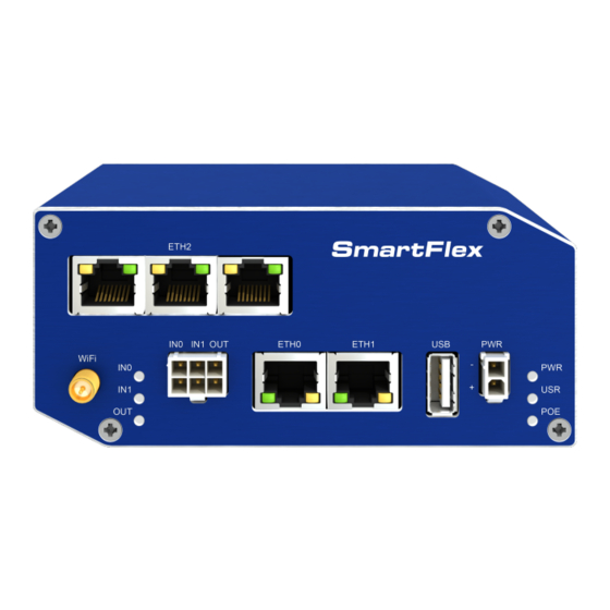
SmartFlex SR300 5.7 Description of the rear panel The rear panel contains only one holder for SD card (SD) and RST button used to restore default configuration and reboot the router. 5.8 Description of the front panel On the front panel is the following:... -
Page 20: Status Indication
SmartFlex SR300 5.8.1 Status indication About router status inform nine LED indicators on the front panel. Each ETH port has two additional LEDs that provide information about port status. Caption Color State Description Green Blinking Router is ready Starting of the router Fast blinking Updating firmware... -
Page 21: Power Connector Pwr
SmartFlex SR300 5.8.2 Power connector PWR Panel socket 2-pin. Pin number Signal mark Description GND(-) Negative pole of DC supply voltage VCC(+) Positive pole of DC supply voltage (+10 to +60 V DC) Table 10: Connection of power connector Figure 11: Power connector Unit has to be supplied by a power supply specified as a Limited Power Source (LPS) ac-... - Page 22 SmartFlex SR300 In applications requiring low power consumption (such as solar power - not 7/24 mode) is strictly recommended to use "LPM" mode prior to powering down the entire router. All metal parts are connected together with the negative pole of power supply (common pole).
-
Page 23: Antenna Connector Wifi
SmartFlex SR300 5.8.3 Antenna connector WiFi If the router is equipped with WiFi module on the customer’s request, appropriate antenna is connected to the reverse SMA connector (WiFi). The extarnal antenna is connected by screwing this antenna to the reverse SMA connector on the router’s front panel (see the figure below). -
Page 24: Microsd Card Reader
SmartFlex SR300 5.8.4 MicroSD card reader The microSD card reader is placed on the rear panel of the router (there is only a single slot). This card reader allows the router to operate with memory cards microSD. Technical specifications are stated in the table below. - Page 25 SmartFlex SR300 In the output of the command find out the entry for the microSD card, for example: mmcblk0: p1 To mount the card to to mnt directory, use the mount command: mount /dev/mmcblk0p1 /mnt For more information about the commands for creating, mounting, checking and unmounting a file system on a microSD card, see the application note for...
-
Page 26: Ethernet Ports (Eth0 And Eth1)
SmartFlex SR300 5.8.5 Ethernet Ports (ETH0 and ETH1) The panel socket RJ45 is used for this interface. The isolation barrier of the Ethernet signal ports against the ground is 1500 V. Signal mark Description Data flow direction TXD+ Transmit Data – positive pole... -
Page 27: Power Over Ethernet (Poe)
SmartFlex SR300 5.8.6 Power over Ethernet (PoE) On the router models with PoE, the PoE+ standard IEEE 802.3at-2009 and PoE standard IEEE 802.3af-2003 are supported in both Ethernet ports (ETH0, ETH1). The PoE PD version allows the router to be powered over the Ethernet by another PoE PSE device. The PoE PSE version also allows the router to power other devices over the Ethernet. -
Page 28: Poe Pse Usage
SmartFlex SR300 PoE PSE Figure 18: PoE PSE usage The power supply used with the PoE PSE router has to provide voltage from 44 to 57 V DC and the output power has to be at least 65 W for full PoE+ use (Class 4) in both Ethernet ports (ETH0 and ETH1). -
Page 29: Usb Port
SmartFlex SR300 5.8.7 USB Port Panel socket USB-A. Signal mark Description Data flow direction +5 V Positive pole of 5 V DC supply voltage, 0.5 A USB data - USB data signal – negative pole Input/Output USB data + USB data signal – positive pole... -
Page 30: I/O Port
SmartFlex SR300 5.8.8 I/O Port Panel socket 6-pin. Signal mark Description Binary input 0 Binary input 0 Binary input 1 Binary input 1 Binary output Binary output Table 15: Connection of I/O port Figure 20: I/O connector The I/O user Interface is designed for the processing of binary input and control (setting) of binary output. -
Page 31: Binary Connection
SmartFlex SR300 Binary output Binary output parameters: – 60 V AC / 300 mA – 60 V DC / 300 mA The current of the binary output is limited by a resettable fuse (300 mA). Binary inputs and output connections... -
Page 32: Reset
SmartFlex SR300 5.8.9 Reset When PWR LED starts flashing on the front panel, it is possible to restore the default con- figuration of the router by pressing the RST button on the rear panel. After pressing this button the default configuration is restored and then router reboots (green LED will be on). -
Page 33: Interfaces Description
SmartFlex SR300 5.9 Interfaces Description There are available versions with one of the following interfaces: SWITCH interface 5.9.1 SWITCH interface Three LAN ports of SWITCH interface for SmartFlex routers (RJ45 connectors for connect- ing Ethernet devices) act as a typical switch device. This means that the router reads Ethernet frames (data packets on an Ethernet link) from any port on SWITCH interface and transmits them on other ports of the SWITCH interface. -
Page 34: First Use
SmartFlex SR300 6. First Use 6.1 Connecting the router before first use Before putting the router into operation it is necessary to connect all components which are required to run your applications. The router can not operate without connected power supply. -
Page 35: Start
SmartFlex SR300 6.2 Start The router is put into operation when the power supply is connected to this router. By default, the router will automatically start to log on to the default APN. DHCP server will start to assign addresses for devices on the Ethernet port ETH0. Router’s behavior can be changed via the web interface. -
Page 36: Entering Login Information
SmartFlex SR300 Figure 26: Entering login information Figure 27: Router web interface... -
Page 37: Technical Parameters
SmartFlex SR300 7. Technical Parameters 7.1 Basic parameters SmartFlex SR300 Temperature range Operating -40 C to +80 C Storage -40 C to +85 C Cold start -40 C Humidity Operating 0 to 95 % relative humidity non condensing Storage 0 to 95 % relative humidity non condensing... -
Page 38: Standards And Regulations
SmartFlex SR300 7.2 Standards and regulations The router complies with the following standards and regulations: Standards and regulations Radio ETSI EN 300 328, ETSI EN 301 893 ETSI EN 301 489-1, ETSI EN 301 489-1, ETSI EN 301 489-17 Safety... -
Page 39: Type Tests And Environmental Conditions
SmartFlex SR300 7.3 Type tests and environmental conditions Phenomena Test Description Test levels EN 61000-4-2 Enclosure contact 6 kV (crit. A) Enclosure air 8 kV (crit. A) RF field AM EN 61000-4-3 Enclosure 20 V/m (crit. A) modulated (80 – 2700 MHz) 3 V/m (crit. -
Page 40: Technical Parameters Of Wifi
SmartFlex SR300 7.4 Technical parameters of WiFi WiFi Antenna connector R-SMA – 50 Supported WiFi band 2.4 GHz, 5 Ghz Standards 802.11a, 802.11b, 802.11g, 802.11n 2.4 GHz supported channels 1, 2, 3, 4, 5, 6, 7, 8, 9, 10, 11, 12, 13... -
Page 41: Technical Parameters Of Power Over Ethernet (Poe)
SmartFlex SR300 7.6 Technical Parameters of Power over Ethernet (PoE) Standards IEEE 802.3at-2009 (PoE+) and IEEE 802.3af-2003 (PoE) are supported. Ca- bling needed is Category 5, up to 12.5 . It is possible to use a passive PoE injector. PoE PD: parameters for opposite PSE Input voltage range 42.5 –... -
Page 42: Related Documents
SmartFlex SR300 8. Related Documents Advantech Czech: Start Guide, Advantech Czech: Configuration Manual for SmartFlex Routers. -
Page 43: Troubleshooting
SmartFlex SR300 9. Troubleshooting If you cannot connect to the router from your PC, your network card may be configured in such a way that it is not possible to connect to the router. Take one or more of the following steps in order to solve the problem: Make sure your PC’s network card is configured to obtain the IP address form the... - Page 44 SmartFlex SR300 – Error resolving hostname: no such file or directory – Connect to DynDNS server failed L2TP or IPSec isn’t establishing. Check the "System Log" page for error messages. IPSec tunnel establishes but the communication does not run. Probably there are bad routing rules defined in the connected devices, or the default gateway.
-
Page 45: Customer Support
SmartFlex SR300 10. Customer Support Customer Support for Europe Advantech Czech s.r.o. Sokolska 71 562 04, Usti nad Orlici, Czech Republic Phone: +353 91 792444 Fax: +353 91 792445 E-mail: iiotcustomerservice@advantech.eu Web: www.advantech.com Customer Support for NAM Advantech B+B SmartWorx... - Page 46 SmartFlex SR300 We, Advantech Czech s.r.o., declare that the radio equipment narrated in this user’s manual complies with Radio Equipment Regulations 2017 (S.I. 2017 No. 1206). We, Advantech Czech s.r.o., declare that the radio equipment narrated in this user’s manual complies with Directive 2014/53/EU.
Need help?
Do you have a question about the SmartFlex SR300 and is the answer not in the manual?
Questions and answers