Tuttnauer 5075 Technician Manual
Hide thumbs
Also See for 5075:
- Technician manual (134 pages) ,
- Operation and maintenance manual (95 pages) ,
- Operation & maintenance manual (87 pages)
Table of Contents
Advertisement
Advertisement
Table of Contents

Related Manuals for Tuttnauer 5075


Summary of Contents for Tuttnauer 5075
- Page 1 MANUAL EL-D Standard Autoclave ELPVC-D Including the Pre-Vacuum Option Models 5050 and 5075 Cat. No. MAN205- 0570000EN Rev. A Tuttnauer Europe b.v., Hoeksteen 11, 4815 PR, Breda, P.O. Box 7191, 4800 GD Breda, Netherlands. +31/76-5423510, Fax: +31/76-5423540...
-
Page 3: Table Of Contents
Load on counter ..................... 10 Construction....................10 Environment Emission Information ............. 10 Directives and Standards ................10 Electrical Data ....................11 2.10 Overall Dimensions Models 5050, 5075 EL ..........12 2.11 Symbol Description ..................13 2.12 Technical Specifications EL-D ..............14 2.13 Water quality .................... - Page 4 Preliminary Operations for Each Technician Call ........64 Safety tests after repair .................. 64 Dismantling the Outer Cover of the Autoclave ..........65 Replacing the chamber heater............... 65 Replacing the Safety Valve ................66 Cleaning and Replacing the Electrode ............67 Replacing the PT100 Temperature Sensor ...........
- Page 5 TABLE OF CONTENT (Cont.) DRAWINGS PAGE NO. FRONT VIEW .......................... 17 REAR VIEW ..........................18 OVERALL DIMENSIONS Models 3840, 3850 ELCPVGBH-D.......... 12 WATER OUTLET STRAINER ....................98 PIPING DRAWING ....................... 105 ELECTRICAL WIRING DIAGRAM .................. 106 SWITCH BOX WIRING DIAGRAM .................. 114 OPEN SWITCH BOX ......................
-
Page 6: Introduction
INTRODUCTION This manual, together with the operator’s manual, forms the complete edition of the Operation and Maintenance instructions. This manual is intended for the use of the technician. It is forbidden for unqualified and unauthorized personnel to service the autoclave in accordance with the instructions in this manual. Any unauthorized service may result in the invalidation of the manufacturer’s guarantee. -
Page 7: Installation Instructions
INSTALLATION INSTRUCTIONS The following utilities have to be connected (Refer to the drawing below ‘Rear View’ of the autoclave). Power outlet, as detailed in the table below: 3 Ph, 400V/50/60Hz Power Recommended Circuit Breaker If the 3 phase autoclave has to be connected to a one phase power network, 1 x 230V, 50/60Hz., connect the 1ph 230V power source to the supplied switch box that has a 1 phase input (from the power source) and a 3 phase output (to the autoclave). -
Page 8: Installation Site
Connection of the pressure regulator This paragraph refers to the pressure regulator of the feed water and to the pressure regulator of the mineral free water. 1. Attach the pressure regulator to the facility's water outlet. 2. Connect the supplied flexible hose to the pressure regulator's assembly outlet and to the autoclave's water inlet. - Page 9 Caution: Before moving the autoclave, verify that the electrical, air and water connections have been disconnected, and there is no pressure in the chamber. Do not drop this device! Page 7...
-
Page 10: Technical Data
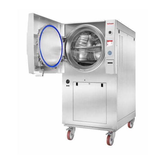
TECHNICAL DATA Introduction Models 5050 and 5075 ELPV-D/ELCPV-D are table-top sterilizers designed especially for the sterilization of instruments, liquids, medical waste, and other materials in hospital laboratories, medical laboratories, research institutes, food laboratories and pharmaceutical facilities. A computerized control unit ensuring a fully automatic sterilization cycle controls the autoclave. -
Page 11: Stand - By Heating Mode
Only technical personnel having proper qualifications, holding technical documentation and adequate test instrumentation are authorized to undertake repair or service. Stand – by heating mode The autoclave provides an option of heating the chamber in stand-by mode between cycles with a very low power in order to reduce total cycle time (1.6% of the total power only). -
Page 12: Load On Counter
Power Model Voltage current electrical consumption shock 3 Ph, Class I 6 x 1100W 5075 400V/50Hz (IEC 60601-1) Class I 3 Ph, 4 x 1100W (IEC 5050 400V/50Hz 60601-1) Attention: The electrical net must be protected with a current leakage safety relay. -
Page 13: Electrical Data
2. ISO 13485:2003 – Quality systems – Medical devices. Electrical Data Line Protection against Power Supply Voltage Model current electrical shock consumption Class I 5075 6 x 1100W 3 Ph, 400V/50Hz (IEC 60601-1) Class I 5050 4 x 1100W 3 Ph, 400V/50Hz (IEC 60601-1) Page 11... -
Page 14: Overall Dimensions Models 5050, 5075 El
1.10 Overall Dimensions Models 5050, 5075 EL TOP VIEW FRONT VIEW Model 5050 5075 Dimensions 34.6 34.6 Overall 28.7 28.7 Dimensions 32.1 1045 41.1 Maximum 1440 56.7 1640 64.6 dimensions 31.6 31.6 (door open) 24.7 24.7 Distance between supporting legs 23.4... -
Page 15: Symbol Description
MODEL PROPERTIES 5050 5075 Chamber diameter in mm Chamber depth in mm 102 lit. 160 lit. Effective Chamber volume 27 US gal 42.3 US gal Height (mm) Overall Width (mm) dimensions Length (mm) 1100 Maximum Width (mm) dimensions Height (mm) -
Page 16: Technical Specifications El-D
Page 14... -
Page 17: Water Quality
1.13 Water quality Water for generating steam The distilled or mineral – free water supplied to the autoclave should have the physical characteristics and maximum acceptable level of contaminants indicated in the table below: Physical Characteristics and Maximum acceptable contaminants levels in steam for sterlizers (According to EN 13060:2004). - Page 18 RO removes particulate matter, organic molecules and pyrogens that DI cannot remove RO water is less corrosive to steel and copper than DI water. RO maintenance requirements are less demanding than those of the DI units. Therefore the use of mineral free water will contribute to better performance and longer life of the autoclave.
-
Page 19: Front View
FRONT VIEW Description Autoclave cover Safety valve Validation port (under door cover) Water reservoir cover Pressure gauge Water reservoir – assembly Reservoir water drain valve (under Control panel display door cover) Ring for drain valve (under door Control panel keyboard cover) Printer Cover RJ45 Ethernet port... -
Page 20: Rear View
REAR VIEW Description Cut off Circuit breaker Electricity Strainer Drain Tap Water Air Inlet Page 18... -
Page 21: Control Panel
CONTROL PANEL CONTROL PANEL DRAWING Description Display Keypad: Up Button Keypad: Start/Stop Button Keypad: Down Button Printer Page 19... -
Page 22: Description And Functions Of The Front Panel Keyboard
Description and Functions of the Front Panel Keyboard The front panel is composed of 3 sections: 1. Display screen. 2. Keypad. 3. Printer Display screen The display is a LCD panel used to display the current status of the autoclave while using Operational Messages and Error Messages. Program description: ... - Page 23 Keypad The keypad consists of three keys as described below: UP key This key has the following functions: In the menu directories: o This key enables the operator to browse through the cycles. In the directories available: o When the cursor is blinking on a number, the UP ▲ key increases its value.
-
Page 24: Tests
TESTS Installation Tests The service technician shall perform the following preliminary checks before operating the autoclave: a. Integrity Check Perform a visual check to verify that there are no dents, scratches, broken gauges, etc. Leveling Check Check that the autoclave is leveled. Leakage current test Check the precise operation of the earth leakage relay. -
Page 25: Water Quality
Observe the closing device for excessive wear 5 years Observe the closing device for excessive wear Safety tests (pressure vessel, efficiency, electrical) shall be performed in accordance with local rules or regulations, by an authorized inspector. Only an authorized technician shall perform the 6-months and yearly tests! WATER QUALITY Physical Characteristics and Maximum acceptable contaminant levels in water or steam, for steam generator and... -
Page 26: Safety Features
The use of heavy scaled water for the vacuum pump cooling, can cause blocking of the rotor and put the pump out of operation. This invalidates the guarantee for the vacuum pump. Safety Features This autoclave includes built-in safety features such as: ... -
Page 27: Description Of The Control System
DESCRIPTION OF THE CONTROL SYSTEM. BLOCK DIAGRAM HARDWARE SOFTWARE COMPONENTS Main board CPU +memory- Backup power input 24/12 I/O Board 24/12 MCIMX27LVOP4A+MC13783VK5 CPU- STM32F103R6T6 Input R.T.C (including Battery) M41T81SM6E Input -24 Digital Outputs Memory card expansion -2 Analog outputs COM1 MT46H32M16LFBF- (RS232) -9 Digital inputs... -
Page 28: Description Of The Programmable Component
Description of the programmable component: Interfaces to users Keypad: The keypad has three push buttons: Down key Up key Start/stop key Display: The control system has a graphical display USB socket: The USB socket is intended to load cycles' history from flash a memory (disk on key). -
Page 29: Calibration
5.2.1.3 Digital outputs Digital Outputs Description Chamber heaters SSR that operates the chamber heaters J13/6 Water pump / Option , relay that operates the water J13/10 water valve pump / water valve Vacuum pump / Option , relay that operates the water to vacuum vacuum pump / water to vacuum J13/12... - Page 30 Reference temperature tool ¼” BSP adaptor (for the validation port) Reference pressure tool: vacuum / pressure gauge in Psig. Calibrating the temperature sensor In case of calibrating with PT-100 Simulator, please select Celsius and kPa units. Enter the MENU screen by pressing the UP and DOWN keys simultaneously for 2-3 seconds.
- Page 31 Move the cursor to "Analog inputs calibration" with the UP and DOWN keys. When it is blinking, select it by pressing the START/STOP key. Move to "Calibrate analog input" with the UP and DOWN keys, and then when it is blinking select it with the START/STOP key Move the cursor to "Chamber Temperature"...
- Page 32 This is a typical calibration screen. This screen presents the current read temperature on screen top right. On top right of the screen, the current temperature read is presented. RH – Temperature is read by the control system at a high temperature point. AH –...
- Page 33 Now press the UP and DOWN keys simultaneously to return to the previous screen until OPERATION SCREEN will be present Calibrating the pressure sensor In order to calibrate the pressure sensor repeat stages 1-5 on page 1 "Calibrating the temperature sensor" Move the cursor to "Chamber pressure"...
- Page 34 The calibration is comparing the system read Pressure (Measured by the control system) to the actual Pressure measured by reference device in two points at least. Setting Pressure: Setting Pressure done by changing the read Pressure to be equal to the actual Pressure.
-
Page 35: Software Development Plan
Software development plan: The hardware is consisted of cards: MAIN and IO Main card Lithium coin Ethernet Connector Connector Power Supply battery T.H Connector Not in use to Keypad to IO Board Connector Horizontal 4V DC) 3V 48mAh Connector to Connector to Connector LCD display... - Page 36 Development tools (MAIN card) The software develop environment is on Microsoft Visual Studio 2005 that includes the Microsoft Platform Builder for Windows CE 6.0. The specific Tuttnauer system application is written in C Sharp.net on Microsoft Compact Framework .net IO Card...
- Page 37 transporting this data according to the request in the communication channel RS-232 to the personally adapted protocol. At the end of the check process of the digital and analog ports, the communication channel is checked, in case of receiving a request, the request is checked and if the request is legitimate it will be taken care of.
- Page 38 MAIN and IO cards communication protocol between IO board to Main Board Communication protocol between IO to Main boards is described below. The communication manged by the Main board (master), the IO functions as slave 1. There are six communication functions. The communication functions (to read or write) identified by number.
-
Page 39: Checking And Changing Parameters And Other Data
CHECKING AND CHANGING PARAMETERS AND OTHER DATA When the system is ready, enter the QUICK OPTIONS screen by pressing the UP and DOWN keys simultaneously. Note: To exit every screen: move the cursor to Exit by pressing UP or DOWN keys and then press START/STOP key. - Page 40 4. The following screen will be displayed: 5. Move the cursor to the required item and press START/STOP key. 6. The time shown on the screen will be added to the current value and you will return to the cycle main screen. For example, if the dry time was 2 min., and you chose 10 minutes on the Add Dry Time screen, the dry time for the current cycle will be 12 minutes.
- Page 41 Export to USB This directory includes two subdirectories (see below) 1. Move the cursor to Export to USB 2. Press the START/STOP key. 3. The following screen will be displayed: Page 39...
- Page 42 Export all settings to USB device This subdirectory allows exporting all settings to USB device 1. Insert the USB device into the USB socket. 2. Press START/STOP key on the Export all settings to USB device item. 3. The following screen will appear: In order to exit this subdirectory, press the START/STOP key.
- Page 43 Print cycles This subdirectory allows to send cycle information to the printer. 1. Move the cursor to Print cycles. 2. Press the START/STOP key. 3. The following screen will be displayed: 4. Move the cursor to the required item and press START/STOP key 5.
- Page 44 1. Move the cursor to Version Information. 2. Press the START/STOP key. 3. The following screen will be displayed: 1. To enter the sub directories, move the cursor by pressing UP or DOWN keys to the required item and press START/STOP. View current version information This subdirectory enables the operator to see the current version information as described below:...
- Page 45 Operational System – Microsoft Windows CE. Version 6.0. DLL size Software Major Minor Automatic Bugs update date change change builder repair Major change Concept change e.g.: changing operating system, Changed by the in accordance with the change programmer sequence. ...
- Page 46 1. Move the cursor to Start cycle by clock. 2. Press the START/STOP key. 3. The following screen will be displayed: When entering the START CYCLE BY CLOCK screen, the time is displayed. The cursor is blinking on the "minute" digit. The time is displayed in the form “HH:MM”.
- Page 47 Cancelling the START CYCLE BY CLOCK To cancel the START CYCLE BY CLOCK move the cursor by pressing START/STOP key to Disable and press UP or DOWN keys. In order to exit this subdirectory, press the UP and DOWN keys simultaneously. Set date and time This subdirectory enables the operator to set date and time.
-
Page 48: Entering The Main Menu
After changing the time and the date, by pressing the START/STOP key move the cursor to Set. Confirm the new time and date by pressing UP or DOWN keys. The following screen will appear: Entering the main menu When the system is ready, enter the QUICK OPTIONS screen by pressing the UP and DOWN keys simultaneously. - Page 49 Press the UP or DOWN keys to move the cursor to Admin and press START/STOP key. The following screen will be displayed: 0000 is displayed on the screen with the cursor blinking on the right digit. To increase or decrease the digits, press the UP or DOWN keys. After changing the code to 0001 move the cursor to Set by pressing the START/STOP key.
-
Page 50: Directories And Subdirectories
In order to exit the Main Menu screen move the cursor to Exit by pressing START/STOP Key. When Exit is blinking press UP or DOWN keys. To browse through the directories, use the UP or DOWN keys. When the required directory is blinking, press the START/STOP key. The required screen will be displayed. -
Page 51: Cycle Parameters (Custom Program = Duplicate Cycle)
Reset atmospheric pressure Printer test Print all gain and offset Cycle Parameters (Custom program = duplicate cycle) This directory applicable only for custom 1 and custom 2 programs Subdirectory Property Purge Time Purge Purge Temperature Pulse A Count Pulse A Stay Time Pulse A Low Pressure Pulse A High Pressure Create Pulse... - Page 52 Purge Purge Time Typical display for Purge subdirectory Choose and enter Purge Time. SET PARAMETER screen will be displayed Set the required value, move to Set and press UP or DOWN keys to confirm the parameter value. In order to exit move the cursor to Exit and press UP or DOWN keys Purge Temperature Repeat the action mentioned in temperature Purge Time...
- Page 53 Typical display for Create Pulse subdirectory Choose and enter Pulse A Count SET PARAMETER screen will be displayed Set the required value, move to Set and press UP or DOWN keys to confirm the parameter value. In order to exit move the cursor to Exit and press UP or DOWN keys Pulse A Stay Time Repeat the action mentioned in Pulse A Count above.
- Page 54 Typical display for Keep Heat subdirectory Choose and enter Temperature 1 Stay. SET PARAMETER screen will be displayed Set the required value, move to Set and press UP or DOWN keys to confirm the parameter value. In order to exit move the cursor to Exit and press UP or DOWN keys Temperature 1 Stay Time Repeat the action mentioned in temperature 1 Stay above...
- Page 55 Repeat the action mentioned in 7.4.2.1 Sterilization Temperature Cooling Cool Mode Typical display for Cool Mode subdirectory Choose and enter Cool Mode SET PARAMETER screen will be displayed Set the required value, move to Set and press UP or DOWN keys to confirm the parameter value. In order to exit move the cursor to Exit and press UP or DOWN keys Cool End Temperature...
- Page 56 SET PARAMETER screen will be displayed Set the required value, move to Set and press UP or DOWN keys to confirm the parameter value. In order to exit move the cursor to Exit and press UP or DOWN keys Drying Dry Time Typical display for Dry Time subdirectory Choose and enter Dry Time...
-
Page 57: System Parameters
Choose and enter End Temperature SET PARAMETER screen will be displayed Set the required value, move to Set and press UP or DOWN keys to confirm the parameter value. In order to exit move the cursor to Exit and press UP or DOWN keys Global Bio Hazard (Option) - Page 58 In order to enter to the sub directories move the cursor by pressing UP or DOWN keys to the required item and press START/STOP key In order to exit this screen follows one of the next: Move the cursor to Exit with the UP or DOWN keys and select it by pressing the START/STOP key.
- Page 59 Print Rate Sterilization This subdirectory allows to change the printing rate during sterilization stage. 1. To increase or decrease the digits, press the UP or DOWN keys. 2. After changing the value move the cursor to Set by pressing the START/STOP.
-
Page 60: Maintenance
2. After changing the value move the cursor to Set by pressing the START/STOP. 3. When Set is blinking, press the UP or DOWN keys in order to confirm changes and return to the previous screen. 4. In order to exit this screen follows one of the next: ... - Page 61 5. Remove the USB device from the USB Socket 6. In order to exit this screen and return to MAINTENANCE directory press START/STOP key. 7. In order to exit the MAINTENANCE directory follows one of the next: Move the cursor to Exit with the UP or DOWN keys and select it by pressing the START/STOP key.
- Page 62 Once you have a custom cycle created by duplication, you will see Change the Keep Heat Time option available in the menu as explained below. 1. Choose you custom cycle (in our example, 7B) 2. Login as Admin (see 6.3 Entering the main menu). 3.
- Page 63 8. Change the required parameter. 9. To increase or decrease the digits, press the UP or DOWN keys. 10. After changing the value move the cursor to Set by pressing the START/STOP key. 11. When Set is blinking, press the UP or DOWN keys in order to confirm changes and return to the previous screen.
- Page 64 Print Test This subdirectory enables the operator to test the printer. When pressing START/STOP key on the Printer Test item the printer will print out the following print out: Cycle errors: None Canceled By User Door is open Analog Input Error I/O Card Failed Power Down Invalid Parameter Value...
- Page 65 Press the UP and DOWN keys simultaneously Print All Gain and Offset This subdirectory enables the operator to print all the gain and offset values. When pressing START/STOP key on the Print all gain and offset item the printer will print out the following: Drain Temperature G:000.0400;O:-004.0000 Chamber Temperature...
-
Page 66: Maintenance And Replacement Procedures
MAINTENANCE AND REPLACEMENT PROCEDURES Preliminary Operations for Each Technician Call 1. In order to maintain efficient service, the technician must perform the following: Cleaning the following, if requires cleaning: Chamber, trays and trays holder. Filters. Bottom parts and plungers of the solenoid valves. ... -
Page 67: Dismantling The Outer Cover Of The Autoclave
Dismantling the Outer Cover of the Autoclave Caution! Before starting, disconnect the instrument from the power source and ensure that there is no pressure in the autoclave. Allow the autoclave to cool before removing outer covers. 1. Unscrew the screws (2) holding the upper cover (1). 2. -
Page 68: Replacing The Safety Valve
Replacing the Safety Valve Caution! Before starting, be sure that the electric cord is disconnected and that there is no pressure in the autoclave. Note: this instruction refers to both, PED and ASME approved safety valves 1. Remove the outer cover of the autoclave. 2. -
Page 69: Cleaning And Replacing The Electrode
Description Cat. No. Description Cat. No. Chamber SVL029-0028 Safety valve base CMV100-0004 2.8 Bar safety ASME valve SVL029-0090 Screw BOL190-0150 40 psi Replacing the PT100 Temperature Sensor Caution! Before proceeding, make sure that the electric cord is disconnected and there is no pressure in the autoclave. Remove the autoclave outer covers. - Page 70 Insert a screwdriver in the holes on the sides of the door cover and unscrew the inner closing arm guide (see the figure below). Insert a screwdriver in the holes on the sides of the door cover and unscrew the 4 screws assembling the door cover to the door (see the figure below).
-
Page 71: Replacing The Door Gasket
See the figures of the disassembling procedure above. Open the autoclave's door. Attach the door cover to the door so that the door cover hinges match the hinges of the door itself (1, figure below). Insert the four screws assembling the door cover to the door. Insert a screwdriver in the holes on the sides of the door cover and tighten the 4 screws assembling the door cover to the door. -
Page 72: Replacing The Micro-Switch
Description Cat. No. Segment LOK387-0062 Screw M5 x 16 BOL191-0162 Gasket GAS080-0203 Screw M5 x 25 BOL191-0240 Spring lock washer M5 NUT193-0325 Nut M5 NUT192-0192 Replacing the micro-switch 1. Unscrew the 2 screws (1). 2. Unscrew the nut (2) and remove the micro-switch. 3. - Page 73 Caution! Before starting, disconnect the instrument from the power source and ensure that there is no pressure in the autoclave. Allow the autoclave to cool before replacing the Panel. Unscrew the five side fastening screws (1). Pull the panel out for approx. 30 centimeters. Remove the protective cover (2) Remove the digital I/O card (4) and the main card (5).
-
Page 74: Replacing The Printer Door
Remove the display (4) and the keypad (5). To do so, unscrew and disconnect the display, then pull the keypad inwards. Remove the printer (3) (see sec. 7.12 "Replacing the Printer"). Assemble the above parts (see steps 7-10) on the new panel. Assemble the panel and fasten it to the autoclave with the 4 fastening screws (see step 1). -
Page 75: Replacing The Printer
7.12 Replacing the Printer Caution Before starting, disconnect the instrument from the power source and ensure that there is no pressure in the autoclave. Allow the autoclave to cool before opening the service door. Remove the panel (see sec. 7.10 Replacing the Panel) to reveal the internal part and the electrical connectors. -
Page 76: Replacing The Main Switch
Connect the printer's connectors Connect all the connectors of the board. Lay the control panel on its place. Assemble the panel (see sec. 7.10). 7.13 .Replacing the main switch Caution! Before starting, disconnect the instrument from the power source and ensure that there is no pressure in the chamber. -
Page 77: Replacing The Fuse Of The Transformer
7.14 Replacing the fuse of the transformer Caution! Before starting, disconnect the instrument from the power source. Allow the autoclave to cool before dismantling the outer covers. Remove the autoclave covers (see para. 9.3 “Dismantling the Outer Covers of the Autoclave”). 2. -
Page 78: Replacing The Plunger Or Coil Of The 1/4" Solenoid Valve
7.15 Replacing the Plunger or Coil of the 1/4" Solenoid Valve The solenoid valves may be out of order due to faulty plunger or coil. To repair the solenoid valve – replace the faulty plunger or solenoid Caution! Before starting, disconnect the instrument from the power source and ensure that there is no pressure in the chamber. -
Page 79: Replacing The Plunger Or Coil Of The Baccara Solenoid Valve
7.16 Replacing the Plunger or Coil of the BACCARA Solenoid Valve The solenoid valves may be out of order due to faulty plunger or coil. To repair the solenoid valve – replace the faulty plunger or solenoid Caution! Before starting, disconnect the instrument from the power source and ensure that there is no pressure in the chamber. -
Page 80: Replacing The Air Filter
7.17 Replacing the Air Filter Caution! Before proceeding, make sure that the electric cord is disconnected and there is no pressure in the autoclave. Pull out the filter cover. Pull the air filter out of its seat. Insert a new filter by pressing it into the filter seat. Replace the filter cover. -
Page 81: Replacing The Pressure Transducer
7.18 Replacing the Pressure Transducer Caution! Before proceeding, make sure that the electric cord is disconnected and there is no pressure in the autoclave. Remove the autoclave outer covers. Unscrew the screw (1). Lift and remove the transducer's cap (2) from the transducer (4). If the square gasket (3) remains on the transducer, remove it and install it on the new transducer. -
Page 82: Replacing The Power Supplies, Water Level Board And Relays
3. Unscrew the 6 screws (3). 4. Remove the old circuit breaker and replace it with a new one. Use only an original circuit breaker supplied by Tuttnauer. 5. Assemble the new circuit breaker with the 6 screws (3). 6. Connect the electrical connections (3). -
Page 83: Releasing The Vacuum Pump When The Rotor Is Locked
Part No. Description THE0039-0104 Ground Terminal, Feed-Through, Grey THE039-0107 Terminal, Feed-Through, 4-Conductor, 2.5 mm², Black THE039-0105 Terminal, Feed-Through, 4-Conductor, 2.5 mm², Red ELE035-0144 Power Supply, 24VDC, 1A Terminal, Feed-Through, 2-Conductor, Fuse Disconnect 1 THE-039-0091 1/4X1/4, 4mm² Ground Terminal, Feed-Through, 4-Conductor, 2.5 mm², THE039-0108 Green/Yellow ELE035-0119... -
Page 84: Replacing The Safety Pressure Switch
Unscrew and remove the pressure switch (2) from its seat (3). Replace the pressure switch with a new one, use only an original pressure switch supplied by Tuttnauer. Assemble the pressure switch (2) to its seat (3). Connect the electrical connections (1). -
Page 85: Replacing The Vacuum Pump
7.23 Replacing the Fan of the Electronic Unit Caution! Before starting, disconnect the autoclave from the power source. Allow the autoclave to cool before dismantling the outer covers. Remove the autoclave covers (see para. 9.3 “Dismantling the Outer Covers of the Autoclave”). Unplug the fan plug (1). -
Page 86: Replacing The Water Reservoir Electrode /Float
7.24 Replacing the Water Reservoir Electrode /Float Open the cover Disconnect the wires of the float (1) Unscrew the white plastic nut (2) Pull out the old float (3); insert the new float in the correct direction Apply some leakage prevention glue inside the nut and tighten it Reconnect the wires and close the cover. - Page 87 Page 85...
-
Page 88: Troubleshooting
TROUBLESHOOTING This troubleshooting chart enables the user to solve minor malfunctions, prior to contacting our service department. Only technical personnel having proper qualifications and holding technical documentation (including a technician manual) and adequate information are authorized to service the apparatus. Message / Symbol / Failure Description... - Page 89 Message / Symbol / Failure Description Corrective Action Problem 1 This message is displayed if the 1 Perform a new cycle. temperature raises 7°F (4°C) above sterilization temperature High Temp during the sterilization stage for 2 seconds during sterilization cycle. 2 Door gasket is leaking.
- Page 90 Message / Symbol / Failure Description Corrective Action Problem 3 Faulty heating element. 3 Replace faulty heating element. 1 This message is displayed if the 1 Check and fix the pressure in chamber does not reach compressed air supply. the preset pressure before Low Pressure initiating the cooling stage.
- Page 91 Message / Symbol / Failure Description Corrective Action Problem after preset time, during the air removal stage. RTC Error - 1 Set Current Date And Please Set This message is displayed in order Time. Current Date to set the date and the time. 2 If the problem persists, and Time replace the main board.
- Page 92 Message / Symbol / Failure Description Corrective Action Problem Cycle counter Number of cycles, since last exceeded - periodical maintenance, exceeded Perform, periodical Please call for the preset number as defined by maintenance operations service "cycle counter" parameter. This message is displayed if power Turn on the autoclave and wait down has occurred during the cycle.
- Page 93 Message / Symbol / Failure Description Corrective Action Problem pressure higher (more than 10%) than specified. Safety relief valve does not Safety relief valve is faulty. Replace relief valve close in time (2-3 seconds). Safety relief Replace relief valve and valve leaks Safety relief valve is faulty.
- Page 94 Message / Symbol / Failure Description Corrective Action Problem and Main board. 2 I/O card is faulty (both while cycle 2. replace faulty is running or not). Error Locking 1 One or both micro-switches on the 1 Fix disconnections. (following door frame are disconnected closing the 2 One or both micro-switches on the...
-
Page 95: No Response When Turning On The Autoclave
No response when turning on the autoclave Refer to the electrical diagram No response when turning on the autoclave Circuit breaker on ON position Turn C.B. on Problem persists Problem solved 230V between phase and neutral on C.B. Faulty C.B. Replace C.B. -
Page 96: Solenoid Valve Always Open
Solenoid valve always open Valve always closed Perform In-Out test Valve opens Disconnect valve's plug Valve O.K. Voltage in plug when control unit sends a signal Faulty coil Wire discontinuity Replace coil discontinuity Page 94... -
Page 97: Door Is Closed But The Locking Motor Does Not Work
Door is closed but the locking motor does not work Door is closed but the locking motor does not work Enter "Input-Output" Enter "View Digital output State" Press manually the door switch. See next page appears by "Close Door" Motor operates Motor's fuse burnt Switch pressing... -
Page 98: List Of Spare Parts
LIST OF SPARE PARTS Part No. Description COV507-0009 External Jacket Support Strip WHE070-0015 Leg, PVC ,Bolt Type 3/8", 60mm CMT240-0003 Spacer for Drain Valve, Brass FIT100-0309 Male Elbow 90°, Twin Ferrule, 1/4"NPTx5/16" Tube, Brass FIT100-0297 Male Connector, Twin Ferrule, 1/4"NPTx3/8" Tube, Brass GAS080-0010 Water, Neopren, 2x11x19 mm BOL191-0092... - Page 99 VLV170-0022 Valve, Needle, 1/4", Bronze NPT VLV170-0066 Drain Valve ELC507-0081 CPN064-0031 Keyboard, EZ 9"&11", EZ/3870-D & Hor.-D CTP200-0138 Board, I/O Extension, Bacsoft CTP200-0140 Board, Main Control, Bacsoft ELC258-0012 Shield, Control Unit Boards, Bacsoft ELE039-0048 Terminal, male, brass, w/o isolation, PC1L18704LR, K.S. Terminals POL064-0031 Panel, Control, Assy., 50xx-D POL064-0024...
-
Page 100: Water Outlet Strainer
Cover Door for 50XX-D - Assembly BOL191-0140 Pan Head Machine Screw, Phillips, M4x12, St. St. A2, DIN7985 POL067-0004 Cover, Reservoir, Fill water TRY507-0001 Tray, Perforated, 5075 ML/EL, St.St. CMT196-0001 Bushing, water level electrode GAS086-0001 Tube, Teflon, Water Level Electrode ELE039-0048 Terminal, male, brass, w/o isolation, PC1L18704LR, K.S. -
Page 101: Pressure Vs Temperature For Saturated Steam
PRESSURE VS TEMPERATURE FOR SATURATED STEAM psia InHg °F °C psia psig °F °C 2.95 114.5 0.10 45.8 17.1 219.7 1.18 117.9 104.3 4.44 129.3 0.15 54.1 17.2 219.9 1.18 118.6 104.4 5.90 140.2 0.20 60.1 17.2 220.1 1.19 118.6 104.5 7.39 149.1... - Page 102 psia psig °F °C psia psig °F °C 20.5 229.3 1.41 141.4 109.6 24.6 239.2 1.70 169.7 115.1 20.6 229.5 1.42 142.0 109.7 24.7 10.0 239.4 1.70 170.2 115.2 20.6 229.6 1.42 142.4 109.8 24.7 10.0 239.5 1.71 170.8 115.3 20.7 229.8 1.43...
- Page 103 psia psig °F °C psia psig °F °C 29.4 14.7 249.1 2.02 202.4 120.6 34.6 19.9 258.6 2.39 238.7 125.9 29.5 14.8 249.3 2.03 203.1 120.7 34.7 20.0 258.8 2.39 239.4 126.0 29.5 14.8 249.4 2.04 203.7 120.8 34.8 20.1 259.0 2.40 240.2...
- Page 104 psia psig °F °C psia psig °F °C 40.6 25.9 268.2 2.80 280.0 131.2 45.7 31.2 275.4 3.15 315.0 135.2 40.7 26.0 268.3 2.81 280.9 131.3 45.8 31.3 275.5 3.16 315.9 135.3 40.9 26.2 268.5 2.82 281.7 131.4 45.9 31.5 275.7 3.17 316.8...
-
Page 105: Valves Numbering
VALVES NUMBERING The valves in the drawing and the manual are numbered according to their function. The following list includes all the valve numbers that are in use in Tuttnauer Change-over : steam / electricity Locking door cylinder (front door) - Page 106 Drain – from reservoir Drain – from jacket overflow Drain – from vacuum pump / ejector Drain – from chamber Drain – from cooler DRAIN Drain – from sanitary filter Drain – from steam generator Drain – jacket Drain – condense from seal Exhaust –...
-
Page 107: Piping Drawing
PIPING DRAWING – MODEL 5050, 5075 ELCPVBH Page 105... -
Page 108: Electrical Wiring Diagram
ELECTRICAL WIRING DIAGRAM Page 106... - Page 109 Page 107...
- Page 110 Page 108...
- Page 111 Page 109...
- Page 112 Page 110...
- Page 113 Page 111...
- Page 114 Page 112...
- Page 115 Page 113...
-
Page 116: Switch Box Wiring Diagram
SWITCH BOX WIRING DIAGRAM To enable the connection of the autoclave to the 1 phase electrical net, a special switch box is supplied with the autoclave. This switch box shall be placed on the wall and the wiring connection shall be as described below. Page 114... -
Page 117: Open Switch Box
OPEN SWITCH BOX FROM FROM AUTOCLAVE NETWORK Page 115... -
Page 118: Closed Switch Box
CLOSED SWITCH BOX Page 116...
Need help?
Do you have a question about the 5075 and is the answer not in the manual?
Questions and answers