AgileX BUNKER User Manual
Hide thumbs
Also See for BUNKER:
- User manual (17 pages) ,
- User manual (18 pages) ,
- User manual (23 pages)

Related Manuals for AgileX BUNKER


Summary of Contents for AgileX BUNKER
- Page 1 BUNKER USER MANUAL BUNKER AgileX Robotics Team USER MANUAL V.2.0.0 2023.09 Document version Edited Version Date Reviewer Notes V1.0.0 2023/03/17 谢瑞亲 Document creation 1 / 3 5...
- Page 2 BUNKER integrators and end customers have the responsibility to ensure compliance with the applicable laws and regulations of relevant countries, and to ensure that there are no major dangers in the complete robot application.
- Page 3 ● Carry out remote control within the range of visibility. ● The maximum load of BUNKER is 70KG. When in use, ensure that the payload does not exceed 70KG. ● When installing an external extension on BUNKER, confirm the position of the center of mass of the extension and make sure it is at the center of rotation.
- Page 4 ● The battery of BUNKER products is not fully charged when it leaves the factory. The specific battery power can be read from the voltage display meter at the rear of the BUNKER chassis or the CAN bus communication interface;...
- Page 5 ● The current of the extended power supply at the tail does not exceed 6.25A, and the total power does not exceed 300W; Additional safety advice ● If you have any questions about the use process, please follow the relevant instruction manual or consult relevant technical personnel;...
-
Page 6: Table Of Contents
2.3 Instructions on control demands and movements 3 Getting Started 3.1 Use and operation 3.2 Charging 3.3 Communication using CAN 3.3.2 CAN Cable Connection 3.3.3Implementation of CAN 3.4 Firmware upgrades 3.5 BUNKER ROS Package Use Example 4 Q&A 5 Product Dimensions 5.1 Product outline dimension illustration 6 / 3 5... -
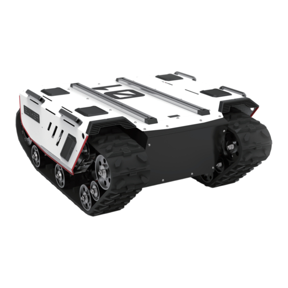
Page 7: Bunker Introduction
5.2 Top expansion stent size description diagram 1 BUNKER Introduction BUNKER is designed as a multi-purpose tracked chassis with different application scenarios considered: simple and sensitive operation, large development space, adapt to various fields of development and application, independent suspension system, high payload and suspension, strong climbing ability, can climb stairs. - Page 8 Chassis height 90mm Track width 150mm Length 560mm Weight About 130kg Weight Load 70kg Type Lithium battery Battery Capacity 30AH Voltage Maximum climbing capacity 30° Maximum Speed 1.5m/s Minimum turning radius Be able to turn on a pivot Maximum obstacle 170mm Performance 2×650W brushless servo...
-
Page 9: Required For Development
1.3 Required for development FS RC transmitter is provided (optional) in the factory setting of BUNKER, which allows users to control the chassis of robot to move and turn; CAN and RS232 interfaces on BUNKER can be used for user s customization. ’... -
Page 10: Instructions On Remote Control
S1 is the throttle button to control the forward and backward of BUNKER; S2 controls the rotation, POWER is the power button, and it can be turned on at the same time. It should be noted that when the remote controller is turned on, SWA, SWB, SWC, SWD all need to be at the top. - Page 11 Figure 2.3 Schematic Diagram of Buttons on FS RC transmitter Remote control interface description: Bunker : model Vol: battery voltage Car: chassis status Batt: Chassis power percentage P: Park Remoter: remote control battery level Fault Code: Error information (Represents byte [5] in 211 frame)
-
Page 12: Instructions On Control Demands And Movements
A reference coordinate system can be defined and fixed on the vehicle body as shown in Figure 2.4 in accordance with ISO 8855. As shown in Figure 2.4, the vehicle body of BUNKER is in parallel with X axis of the established reference coordinate system. -
Page 13: Getting Started
Press down emergency push button at the rear of BUNKER vehicle body; Basic operating procedure of remote control ● After the chassis of BUNKER mobile robot is started correctly, turn on the RC transmitter and select the remote-control mode. Then, BUNKER platform movement can be controlled by the RC transmitter. -
Page 14: Communication Using Can
● Make sure the electricity of BUNKER chassis is powered off. Before charging, please make sure Q2 (key switch) in the rear control console is turned off; ● Insert the charger plug into Q3 charging interface on the rear control panel;... - Page 15 0x00 Normal condition Current status of byte [0] unsigned int8 0x01 Emergency stop vehicle body 0x02 System Error 0x00 Stand by byte [1] Mode control unsigned int8 0x01 CAN command control 0x03 Remote control Battery voltage byte [2] upper 8 bits Actual voltage ×...
- Page 16 bit [0] Low-voltage failure bit [1] Low-voltage warning Remote control signal lost bit [2] protection(0: Normal 1: Lost byte [5] signal) Drive 1 communication bit [3] failure(0: Normal 1: Failure) Drive 2 communication bit [4] failure(0: Normal 1: Failure) bit [5] Reserve, default value 0 bit [6]...
- Page 17 Data length 0x08 Position Function Data type Description Moving speed byte [0] upper 8 bits Actual speed X 1000 (with an signed int16 Moving speed accuracy of 0.001m/s) byte [1] lower 8 bits Rotation speed byte [2] upper 8 bits Actual speed X 1000 (with an signed int16 Rotation speed...
- Page 18 Linear velocity upper 8 byte byte [0] Linear moving speed mm/s(unit) Signed int16 Linear byte [1] Range[-1500,1500] velocitylower 8 byte Linear speed Rotation angular speed byte [2] percentage Signed int16 0.001rad/s(unit) Angular speed byte [3] Range [-1000,1000] percentage byte [4] Reserved —...
- Page 19 Stand by Note[1] Description for control mode When the remote control is power off, the control mode of BUNKER is can command control by default , that means chassis can be controlled by commands directly. Please note that the control mode in command still need to set 0x01 if the speed command need to be executed successfully.
- Page 20 0x00 Clear all failures Failures clear byte [0] Unsigned int8 0x01 Clear motor1 failures command 0x02 Clear motor2 failures In addition to the feedback of chassis status, there are also feedback data from the motors and sensors. Table 3.7 Motor Rotational Speed Feedback Frame Command Name Motor Rotational Speed Feedback Frame Cycle...
- Page 21 Data length 0x08 Location Function Data type Description Reserved 0x00 byte [0] byte [1] Reserved 0x00 Drive temperature byte [2] upper 8 bits Signed int 16 Unit: 1℃ byte [3] Drive temperature lower 8 bits byte [4] Reserved 0x00 byte [5] Drive status Unsigned int 8 Refer to Table 3.9 for detail...
- Page 22 bit [5] Reserved bit [6] Reserved bit [7] Reserved Table 3.10 Odometer Feedback Frame Command Name Odometer Feedback Command Receive- Sending node Receiving node Cycle ms timeout(ms) Steer-by-wire Decision-making 0x311 20ms None chassis control unit Data length 0x08 Location Function Data type Description...
- Page 23 Right wheel odometer highest bit Right wheel odometer byte [4] second highest Right wheel odometer feedback byte [5] Signed int 32 byte [6] Right wheel (Unit: mm) odometer byte [7] second lowest Right wheel odometer lowest Table 3.11 Remote Control Information Feedback Frame Command Remote Control Information Feedback Command Name...
-
Page 24: Can Cable Connection
Range[-100,100] 3.3.2 CAN Cable Connection BUNKER ships with the vehicle and provides a male aviation plug as shown in Figure 3.2. The definition of the wires is: yellow is CANH, blue is CANL, red is the positive power supply, and black is the negative power supply. -
Page 25: 3Implementation Of Can
Figure 3.2 Schematic diagram of aviation plug male connector 3.3.3 Implementation of CAN Correctly start the chassis of BUNKER mobile robot, and turn on FS RC transmitter. Then, switch to the command control mode, i.e. toggling SWB mode of FS RC transmitter to the top. At this point, BUNKER chassis will accept the command from CAN interface, and the host can also parse the current state of chassis with the real-time data fed back from CAN bus. - Page 26 Upgrade Process 1.Plug in the USBTOCAN module on the computer, and then open the AgxCandoUpgradeToolV1.3_boxed.exe software (the sequence cannot be wrong, first open the software and then plug in the module, the device will not be recognized). 2.Click the Open Serial button, and then press the power button on the car body. If the connection is successful, the version information of the main control will be recognized, as shown in the figure.
- Page 27 4.Click the node to be upgraded in the node list box, and then click Start Upgrade Firmware to start upgrading the firmware. After the upgrade is successful, a pop-up box will prompt. 2 7 / 3 5...
-
Page 28: Bunker Ros Package Use Example
CANlight can communication module ×1 ● Thinkpad E470 notebook ×1 ● AGILEX BUNKER mobile robot chassis ×1 ● AGILEX BUNKER remote control FS-i6s ×1 ● AGILEX BUNKER top aviation power socket ×1 Use example environment description ● Ubuntu 18.04 2 8 / 3 5... - Page 29 ● Hardware connection and preparation ● Lead out the CAN wire of the BUNKER top aviation plug or the tail plug, and connect CAN_H and CAN_L in the CAN wire to the CAN_TO_USB adapter respectively; ● Turn on the knob switch on the BUNKER mobile robot chassis, and check whether the emergency stop switches on both sides are released ●...
- Page 30 复 代 sudo apt install can-utils ● If the can-to-usb has been connected to the BUNKER robot this time, and the car has been turned on, use the following commands to monitor the data from the BUNKER chassis 复 代...
- Page 31 *_base:: The core node for the chassis to send and receive hierarchical CAN messages. Based on the communication mechanism of ros, it can control the movement of the chassis and read the status of the bunker through the topic. *_msgs: Define the specific message format of the chassis status feedback topic.
-
Page 32: Product Dimensions
A:Normally, if BUNKER can be controlled by a RC transmitter, it means the chassis movement is under proper control; if the chassis feedback frame can be accepted, it means CAN extension link is in normal condition. Please check the CAN control frame sent to see whether the data check is correct and whether the control mode is in command control mode. - Page 33 5.2 Top expansion stent size description diagram 3 3 / 3 5...
- Page 34 3 4 / 3 5...
- Page 35 3 5 / 3 5...
Need help?
Do you have a question about the BUNKER and is the answer not in the manual?
Questions and answers