AgileX BUNKER User Manual
Hide thumbs
Also See for BUNKER:
- User manual (17 pages) ,
- User manual (18 pages) ,
- User manual (35 pages)
Table of Contents
Advertisement
Quick Links
Advertisement
Table of Contents

Subscribe to Our Youtube Channel
Related Manuals for AgileX BUNKER


Summary of Contents for AgileX BUNKER
- Page 1 BUNKER AgileX Robotics Team User Manual 2020.04 V.2.0.1...
- Page 2 If you have any questions about use, please contact us at support@agilex.ai. Please follow and implement all assembly instructions and guidelines in the chapters of this manual, which is very important. Particular...
- Page 3 The maximum load of BUNKER is 70KG. When in use, When BUNKER has had a defect, please ensure that the payload does not exceed 70KG. contact the relevant technical to deal with it, When installing an external extension on BUNKER, do not handle the defect by yourself.
- Page 4 Do not push BUNKER directly. When charging, make sure the ambient temperature is above 0℃. 5.Maintenance Regularly check the tension of the hanging crawler, and tighten the crawler every 150~200h. After every 500 hours of operation, the bolts and nuts of each part of the car body should be inspected.
-
Page 5: Table Of Contents
CONTENTS 1 Bunker Introduction..............1 1.1 Component list.................1 1.2 Tech specifications................1 1.3 Required for development..............2 2 The Basics..................3 2.1 Description of electrical interface.............3 2.2 Instruction on remote control............4 2.3 Instruction on control demands and movements......4 3 Getting Started................5 3.1 Use and operation................5 3.2 Charging....................6... -
Page 7: Bunker Introduction
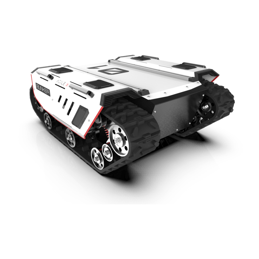
1 BUNKER Introduction BUNKER is designed as a multi-purpose tracked chassis with different application scenarios considered: simple and sensitive operation, large development space, adapt to various fields of development and application, independent suspension system, high payload and suspension, strong climbing ability, can climb stairs. -
Page 8: Required For Development
Communication interface 1.3 Required for development FS RC transmitter is provided (optional) in the factory setting of BUNKER, which allows users to control the chassis of robot to move and turn; CAN and RS232 interfaces on BUNKER can be used for user’s customization. -
Page 9: The Basics
2 The Basics This section provides a brief introduction to the BUNKER mobile robot platform. It is convenient for users and developers to have a basic understanding of BUNKER chassis. Description of electrical interface The interface at rear end is shown in Figure 2-1, where Q1 is CAN and 48V power supply aviation interface;... -
Page 10: Instruction On Remote Control
S1 is the throttle button to control the forward and backward of BUNKER; S2 controls the rotation, POWER is the power button, and it can be turned on at the same time. It should be noted that when the remote controller is turned on, SWA, SWB, SWC, SWD all need to be at the top. -
Page 11: Getting Started
As shown in Figure 2.4, the vehicle body of BUNKER is in parallel with X axis of the established reference coordinate system. Following this convention, a positive linear velocity corresponds to the forward movement of the vehicle along positive x-axis direction and a positive angular velocity corresponds to positive right-hand rotation about the z-axis. -
Page 12: Charging
Basic operating procedure of remote control: After the chassis of BUNKER mobile robot is started correctly, turn on the RC transmitter and select the remote-control mode. Then, BUNKER platform movement can be controlled by the RC transmitter. 3.2 Charging BUNKER is equipped with a standard charger by default to meet customers' recharging demand. - Page 13 The description is given in Table 3.1. Table 3.1 Feedback Frame of BUNKER Chassis System Status Command System Status Feedback Command Name Sending node Receiving node Receive- Cycle(ms)...
- Page 14 Table 3.2 Description of Failure Information Description of Failure Information Byte Meaning bit [0] Check error of CAN communication control command (0:No failure 1:Failure bit [1] Reserved, default 0 bit [2] Reserved, default 0 bit [3] Reserved, default 0 byte [4] bit [4] Reserved, default 0 bit [5]...
- Page 15 byte [2] Rotational speed higher 8 bits signed int16 Actual speed X 1000 (with an accuracy of byte [3] Rotational 0.001rad/s) speed lower 8 bits byte [4] Reserved 0x00 byte [5] Reserved 0x00 byte [6] Count paritybit unsigned int8 0~255 counting loops, which will be (count) added once every command sent byte [7]...
- Page 16 [Note 2]-Information about failure clearing In case the RC transmitter is powered off, the command: 0X00 No failure clearing command control mode of BUNKER is defaulted to command 0x00 No failure clearing command control mode, which means the chassis can be 0X01 Clear battery under-voltage failure directly controlled via command.
- Page 17 * @BRIEF CAN MESSAGE CHECKSUM EXAMPLE CODE * @PARAM[IN] ID : CAN ID * @PARAM[IN] *DATA : CAN MESSAGE DATA STRUCT POINTER * @PARAM[IN] LEN : CAN MESSAGE DATA LENGTH * @RETURN THE CHECKSUM RESULT STATIC UINT8 AGILEX_CANMSGCHECKSUM(UINT16 ID, UINT8 *DATA, UINT8 LEN) UINT8 CHECKSUM = 0X00;...
-
Page 18: Can Cable Connection
For the detailed content of protocol, please refer to CAN communication protocol. 3.4Firmware upgrades The RS232 port on BUNKER can be used by make the upgrading process fast and users to upgrade the firmware for the main smooth. A screenshot of this application is controller in order to get bug fixes and feature shown in Figure 3.3. - Page 19 · USB-to-serial port X 1 · Connect the serial cable onto the upgrade serial · BUNKER chassis X 1 port of BUNKER chassis(need to disassemble the · Computer(Windows operating system)X1 rear electrical plate); · Connect the serial cable to the computer;...
-
Page 20: Attention
4 Attention This section includes some precautions that should be paid attention to for BUNKER use and development. Battery Operational environment The battery supplied with BUNKER is not fully The operating temperature of BUNKER outdoors is -10 charged in the factory setting, but its specific power ℃... - Page 21 A:Normally, if BUNKER can be controlled by a RC transmitter, it means the chassis movement is under proper control; if the chassis feedback frame can be accepted, it means CAN extension link is in normal condition.
-
Page 22: Product Dimensions
6 Product Dimensions 6.1 Product outline dimension illustration... -
Page 23: Top Expansion Stent Size Description Diagram
6.2 Top expansion stent size description diagram...
Need help?
Do you have a question about the BUNKER and is the answer not in the manual?
Questions and answers