AgileX BUNKER User Manual
Hide thumbs
Also See for BUNKER:
- User manual (18 pages) ,
- User manual (23 pages) ,
- User manual (35 pages)
Table of Contents
Advertisement
Quick Links
Advertisement
Table of Contents

Related Manuals for AgileX BUNKER


Summary of Contents for AgileX BUNKER
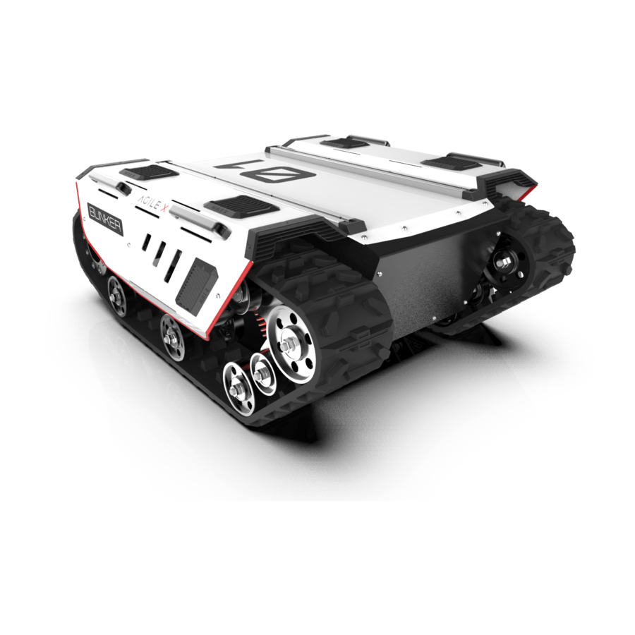
- Page 1 BUNKER AgileX Robotics Team User Manual 2020.08 V.2.0.0...
- Page 2 If you have any questions about use, please contact us at support@agilex.ai. Please follow and implement all assembly instructions and guidelines in the chapters of this manual, which is very important. Particular...
- Page 3 The design and use of the complete system need to comply with the safety requirements established in the standards and regulations of the country where the robot is installed. BUNKER integrators and end customers have the responsibility to ensure compliance with the applicable laws and regulations of relevant countries, and to ensure that there are no major dangers in the complete robot application.
-
Page 4: Table Of Contents
CONTENTS 1 Bunker Introduction 3.4 Firmware upgrades 1.1 Component list 1.2 Tech specifications 4 Attention 1.3 Required for development 4.1 Battery 4.2 Operational environment 2 The Basics 4.3 Electrical /extension cords 2.1 Description of electrical 4.4 Additional safety advice interface 4.5 Other notes... -
Page 5: Bunker Introduction
1.3 Required for development FS RC transmitter is provided (optional) in the factory setting of BUNKER, which allows users to control the chassis of robot to move and turn; CAN and RS232 interfaces on BUNKER can be used for user’ s customization. -
Page 6: The Basics
2 The Basics This section provides a brief introduction to the BUNKER mobile robot platform. It is convenient for users and developers to have a basic understanding of BUNKER chassis. 2.1Description of electrical interface The interface at rear end is shown in Figure 2-1, where Q1 is CAN and 48V power supply aviation interface; Q2 is the power switch;... -
Page 7: Instruction On Control Demands And Movements
Coordinate System for Vehicle Body As shown in Figure 2.4, the vehicle body of BUNKER is in parallel with X axis of the established reference coordinate system. In RC control mode, push the remote control stick S1 forward to move in the positive X direction, push stick S1 backward to move in the negative X direction. -
Page 8: Getting Started
BUNKER is equipped with a standard charger by default to meet customers' recharging demand. The detailed operating procedure of charging is shown as follows: Make sure the electricity of BUNKER chassis is powered off. Before charging, please make sure Q2 (key switch) in the rear control console is turned off;... - Page 9 Table 3.1 Feedback Frame of BUNKER Chassis System Status Command Name System Status Feedback Command Sending node Receiving node Cycle(ms) 接收超时(ms) 0x151 Steer-by-wire chassis Decision-making control unit 20ms 无 Data length 0x08 Position Function Data type Description 0x00System in normal condition...
- Page 10 The command of movement control feedback frame includes the feedback of current linear speed and angular speed of moving vehicle body. For the detailed content of protocol, please refer to Table 3.3. Table 3.3 Movement Control Feedback Frame Command Name Movement Control Feedback Frame Sending node Receiving node...
- Page 11 [Note 1] In case the RC transmitter is powered off, the control [Note 2] Information about failure clearing command: mode of BUNKER is defaulted to command control mode, 0X00 No failure clearing command which means the chassis can be directly controlled via 0x00 No failure clearing command command.
-
Page 12: Can Cable Connection
Upgrade preparation Before connection, ensure the robot chassis is powered off; The RS232 port on BUNKER can be used by users to upgrade the Connect the serial cable onto the upgrade serial port of firmware for the main controller in order to get bug fixes and feature BUNKER chassis(need to disassemble the rear electrical plate);... -
Page 13: Attention
4 Attention This section includes some precautions that should be paid attention to for BUNKER use and development. 4.1 Battery 4.2 Operational environment The battery supplied with BUNKER is not fully charged in the The operating temperature of BUNKER outdoors is -10℃ to 45 factory setting, but its specific power capacity can be displayed... - Page 14 5 Q&A Q: BUNKER IS STARTED UP CORRECTLY, BUT WHY CANNOT THE RC TRANSMITTER CONTROL THE VEHICLE BODY TO MOVE? A: FIRST, CHECK WHETHER THE DRIVE POWER SUPPLY IS IN NORMAL CONDITION, WHETHER THE DRIVE POWER SWITCH IS PRESSED DOWN AND WHETHER E-STOP SWITCHES ARE RELEASED; THEN, CHECK WHETHER THE CONTROL MODE SELECTED WITH THE TOP LEFT MODE SELECTION SWITCH ON THE RC TRANSMITTER IS CORRECT.
-
Page 15: Product Dimensions
6 Product Dimensions 6.1 Product outline dimension illustration 780.84... -
Page 16: Top Expansion Stent Size
6.2 Top expansion stent size description diagram... - Page 17 AgileX Robotics ( Dongguan) CO., Ltd WWW.AGILEX.AI Email: sales@agilex.ai TEL:+86-0769-22892150...
Need help?
Do you have a question about the BUNKER and is the answer not in the manual?
Questions and answers