
Related Manuals for Nordpeis Salzburg L Convection PN-SAL01-450


Summary of Contents for Nordpeis Salzburg L Convection PN-SAL01-450
- Page 1 Installation manual Manuel d’installation Montageanleitung Salzburg L Convection Last updated: 02.12.2022 Art.nr: PN-SAL01-450 / PN-SAL01-300 / CO-SAL01-100 RRF nr: 50 13 3415-1; 50 13 3510...
-
Page 2: Table Of Contents
IMPORTANT SAFETY PRECAUTIONS! INDEX General information about heat accumulating fireplaces 1. Please follow the installation manual when connecting your stove / fireplace to the chimney / Double action damper flue pipe. If connected differently from instruction Airvent please, consider the heat radiation from the flue Cleaning the Smoke Duct System pipe to the surrounding materials. -
Page 3: General Information About Heat Accumulating Fireplaces
Salzburg is equipped with secondary The heat accumulating fireplaces from Nordpeis have combustion technology, which can normally only a long duct system where the heat developed in the be found on modern fireplaces. -
Page 4: Glue
Nordpeis offers a one-year warranty on these parts. water, in order to have a clear indentation between the After this, replacements can be purchased. -
Page 5: Packaging Recycle
Use clean and dry wood with a maximum moisture CERAMIC GLASS content of 20% and minimum 16%. Humid wood requires a lot of air for the combustion, as extra energy/ CANNO T BE heat is required for drying the humid wood and heat RECY C LED effect is therefore minimal. -
Page 6: Choice Of Fuel
Pull the hot ember to the front of combustion chamber when inserting new logs so that For the latest updated version go to www.nordpeis.com the wood is ignited from the front. Place first layer of wood logs perpendicular to the front. The fire should burn with bright and lively flames. -
Page 7: Before Installing A New Fireplace
Warning! Nordpeis AS is not responsible for incorrect installation. Keep the air intakes, supplying combustion and convection air free from blockage. Important to check... -
Page 8: Combustion Pace
The air vent control is turned to the right to increase the air supply to Salzburg L Convection Combustion pace An accumulating fireplace is designed to absorb thermal energy during a relatively short period of relatively intense heat. When the period of intensive combustion is completed, the product will deliver the accumulated heat over a longer period of time. -
Page 9: Some Advice In Case Of Combustion Problems
Some advice in case of combustion problems Error Explanation Solution The chimney is blocked Contact a chimney sweeper / dealer for more information or clean The flue is sooty or there is accumulated soot on the the flue, smoke baffle and burn chamber. No draught smoke baffle The smoke baffle is wrongly positioned... - Page 10 CONSIGNES DE SÉCURITÉ IMPORTANTES: INDEX 1. Veuillez suivre les instructions d’utilisation du manuel Les poêles à accumulation lorsque vous raccordez votre poêle/foyer à la Double système de registres des circula- cheminée/au conduit. Si le raccordement se fait tions des fumées différemment des instructions, veuillez tenir compte du rayonnement thermique du conduit de fumée par Commande d’apport d’air...
-
Page 11: Les Poêles À Accumulation
Pour la combustion dans un poêle à accumulation de courte de refroidissement. chaleur la commande d’apport d’air est normalement Avec les poêles à accumulation de chaleur Nordpeis, laissée ouverte au maximum. Cela garantit une com- la chaleur produite dans la chambre de combustion bustion optimale et minimise les dépôts de carbone... -
Page 12: Mur Pare-Feu
Assurez-vous que les faite du produit. surfaces soient sèches avant d’étendre l’acrylique. Nordpeis garantit ces pièces un an. Une fois la garantie Une fois que le poêle est assemblé, remplir les joints passée, vous pouvez acheter des pièces de rechange. -
Page 13: Porte Et Verre
Allure de combustion Avertissement ! Un produit d’accumulation de chaleur ne doit pas être Utilisez uniquement des pièces de rechange utilisé trop agressivement car cela peut endommager recommandées par le fabricant. le produit. Afin de maximiser les bénéfices d’un produit d’accumulation de chaleur, il est donc important d’opti- Avertissement ! miser le rythme de combustion et la taille... -
Page 14: Conseils Généraux Pour Le Feu
Nordpeis AS n’est pas responsable du montage nouveaux bûches, de sorte que le bois s’allume de l’avant. défectueux d’un poêle.Sous réserve d’erreurs et de modifica Placer la première couche de bûches dans le sens perpen-... -
Page 15: Avant D'assembler Le Poêle
/ pays. Avertissement ! Ne pas obstruer les prises d’air comburant Nordpeis n’est pas responsable quant à l’installation. Avertissement ! Des hottes aspirantes, fonction- Vous devez vérifier la conformité des règlements nant dans la même pièce ou le même espace que locaux concernant (S’il vous plaît noter que cette... -
Page 16: Attention! Procédure De Séchage
Illustration des distances (FIG 1) Rythme de combustion * L’illustration montre la distance approximative entre le sol et le centre du trou pour le raccord avec le conduit Un poêle à accumulation de chaleur est conçu pour de fumée. Considérez une possible inclinaison de la absorber l’énergie thermique pendant une période sortie de fumée avant de faire perforer la cheminée. -
Page 17: Combustion
Problème Explication Solution La cheminée est obstruée. Contacter un cheminée ramoneur pour plus d’informations ou nettoyer la cheminée, le déflecteur et chambre de combustion. La sortie des fumées est remplie de suie ou de la Pas de tirage suie s’accumule sur le déflecteur. Le déflecteur est mal placé. - Page 18 WICHTIGE SICHERHEITSHINWEISE: INHALTSVERZEICHNIS 1. Befolgen Sie beim Anschluss Ihres Kaminofens bzw. Allgemeine Information zu Kamins an den Schornstein bzw. das Rauchgasrohr wärmespeichernden Feuerstellen die Installationsanleitung. Wenn Sie von den Doppeltwirkende Klappe Anschlussanweisungen abweichen, beachten Sie die Ventil für Verbrennungsluft Wärmestrahlung vom Rauchgasrohr, die auf die umliegenden Materialien einwirkt.
-
Page 19: Allgemeine Information Zu Wärmespeichernden Feuerstellen
Abkühlzeit. weitgehend Rußablagerungen im Kanalsystem. Intensives Befeuern hält auch leichter die Sichtscheibe Die wärmespeichernden Feuerstellen von Nordpeis rein. Wünscht man trotzdem eine längere Brennperiode haben ein langes Kanalsystem, bei dem die in der und ein ruhigeres Flammenbild, kann man die Brennkammer entwickelte Wärme durch das... -
Page 20: Kleber
Glätten Sie danach die Oberfläche mit einer Ihres Produktes ab. eingeseiften Fingerspitze oder Schwamm, und Nordpeis gibt auf diese Teile 1 Jahr Garantie. Danach ermöglichen Sie, dass trotz der Glättung eine deutliche können Ersatzteile gekauft werden. Markierung in der Verbindung zwischen den Elementen sichtbar bleibt. -
Page 21: Feuerraumtür Und Sichtscheibe
3. Tipps zur Befeuerung Wiedergewinnung von feuerfestem Glas Feuerfestes Glas kann nicht wiedergewonnen werden! Bruchglas und nicht wiederverwendbares, Befeuerungsrhythmus hitzebeständiges Glas muss als Restmüll entsorgt Zum Anfeuern verwendet man am Besten Anzündwürfel werden. Feuerfestes Glas hat eine höhere und Schnittholz. Zeitungspapier macht viel Asche und Schmelztemperatur und kann daher nicht mit dem außerdem ist Druckerschwärze schädlich für die Altglas entsorgt werden. -
Page 22: Brennstoffwahl
geschlossener Feuerraumtür Ihr Gerät auf extreme Brennstoffwahl Als Brennstoff für den Einsatz eignen sich alle Holzarten Temperaturen aufheizen kann und ein unkontrollier- wie z. B. Birken-, Buchen-, Eichen-, Ulmen-, Eschenund bares Feuer hervorruft. Deshalb sollen Sie nie die Obstbaumholz. Die Holzarten unterscheiden sich Brennkammer ganz mit Holz anfüllen. -
Page 23: Technische Information
Vor der Installation Ihres Gerätes beachten Sie bitte alle Rußablagerungen im Schornstein. geltenden Bestimmungen. *1/ siehe Punkt 9 / Grundsätzliche Anforderungen. Nordpeis ist nicht für Warnung! Lufteinlässe, durch die Verbrennungs- widerrechtliche oder inkorrekte Instalation Ihres Gerätes luft strömt, dürfen nicht blockiert werden. -
Page 24: Wichtig! Austrocknungsprozess
Maßzeichnungen (FIG 1) Der Luftregler wird nach rechts bewegt, um die Luft- *Die Abbildung zeigt die Mitte der ungefähren Höhe in zufuhr für den Salzburg L Convection zu erhöhen. der vorgesehenen Öffnung für das Rauchrohr. Wenn Sie das Loch in den Schornstein bohren, denken Sie an einen eventuellen Anstieg des Rauchrohrs. -
Page 25: Hilfe Bei Problemen Mit Der Verbrennung
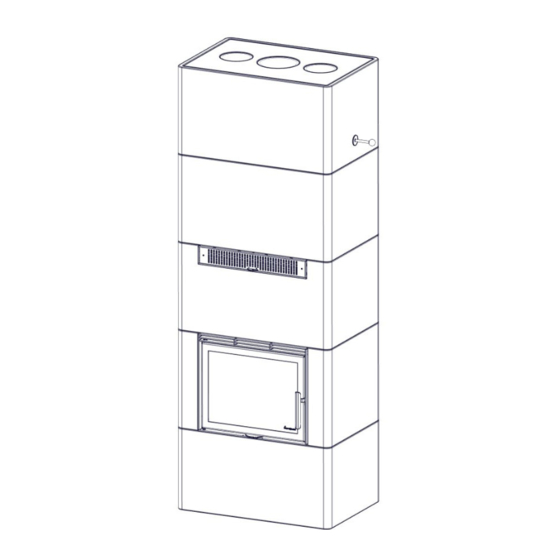
Hilfe bei Problemen mit der Verbrennung FEHLER ERKLÄRUNG BEHEBUNG Zu wenig Zug Rauchrohr verstopft. Schornsteinfeger/Fachhändler kontaktieren oder Rauchrohr und Brennkammer reinigen. Rauchrohr verrußt oder Rußverstopfung an der Rauchgasprallplatte. Rauchgasprallplatte falsch angebracht. Kontrollieren Sie die Position der Rauchgasprallplatte. Siehe Montageanleitung. Das Gerät gibt Unterdruck im Raum. - Page 26 FIG 1 Salzburg L Convection = mm Nordpeis AS Gj e llebekkstubb N-3420 LIIERSKOGE...
- Page 27 FIG 1a Salzburg L Convection extension base = mm 1RUGSHLV$ 6 *MHOOHEHNNVW 1/,,(56.2*(11RUZH\ Nordpeis AS Gj e llebekkstubben N-3420 LIIERSKOGEN, N...
- Page 28 Salzburg L Convection + 1 = mm FIG 1b Nordpeis AS Gj e llebekkstubb N-3420 LIIERSKOGE...
- Page 29 Salzburg L Convection / Salzburg L Convection extension base FIG 1c Salzburg L Convection + 1 = AIR =mm & Revision note: Revision by: Date: Material:...
- Page 30 FIG 2 Salzburg L Convection =Combustible material/ Matières combustibles/ Brennbarem Material/ Materiał palny...
- Page 31 NOTE! It is important to centre the inner core relative to the surround. Ensure that the core is centred after each shift of PowerStone™. Confirm that the inner core is assembled vertically, and that the layers are not offset relative to each other. There should be a 6-10 mm air gap between the inner core and the surround.
- Page 32 Salzburg L Convection FIG 3 Salzburg L Convection + 1 extension X = safety distance X = distance de sécurité X = sicherheitsabstand CO-SAL01-010 (1A) CO-SAL01-02A FIG 3a Salzburg L Convection + extension base X, Y = safety distance X, Y = distance de sécurité X, Y = sicherheitsabstand CO-SAL01-100 (1A)
- Page 33 The base plate (1) or the base extension plate (2) is placed on the floor. It is important that the entire intended contact surface is in actual contact with the floor. This can be ensured by spreading a layer of tile adhesive or thin mortar on the floor before the base plate is placed on the floor.
- Page 34 FIG 3b Salzburg L Convection + extension base CO-SAL01-010 FIG 4 Salzburg L Convection Salzburg L Convection + extension base Salzburg L Convection + 1 extension PI-SAL01-010 PI-SAL01-010 IMPORTANT! The inner core of Powerstone™ must be centered from the first element. Attention! In case of the extension base appliance further assembling steps are the same as standard one.
- Page 35 Bottom air connection Rear air connection Raccordement d’air par le bas Raccordement d’air par l’arrière Unterer Luftanschluss Hinterer Luftanschluss PI-SAL01-020 PI-SAL01-020 PO-SAL01-03B PO-SAL01-03A PO-SAL01-03A...
- Page 36 FIG 5 PI-SAL01-030 FIG 6 PI-SAL01-04B PI-SAL01-04A...
- Page 37 FIG 7 A FIG 7 B 1,5 mm 1,5 mm 22-SAL02-160 0 mm 0 mm CO-SAL01-020 CO-SAL01-020 CO-SAL01-02A Do not use the brackets if the radiation shield will not be used. N’utilisez pas les supports sans l’écran thermique. Verwenden Sie die Halterungen nicht, wenn der Wärmeschutz entfernt wurde.
- Page 38 FIG 8 B FIG 8 A CO-SAL01-020 CO-SAL01-020 CO-SAL01-020...
- Page 39 FIG 9 PI-SAL01-04A PI-SAL01-04B PI-SAL01-05A PI-SAL01-05B PI-SAL01-04B PI-SAL01-04A PI-SAL01-05A PI-SAL01-05B...
- Page 40 FIG 10 Ø 12mm Place the long gasket in the slots on the Powerstone. Use acrylic glue to keep it in place at the height of the frame. This gasket seals the gap around the door/frame. After placing the door/frame, make sure the ends of the gasket overlaps on top of the frame (FIG 12).
- Page 41 FIG 11 10 mm We recommend removing the door during assembly in order not to damage it. The procedure of disas- sembing the door from the frame is shown in FIG 48-50 Nous vous recommandons de retirer la porte pendant le montage pour éviter de l’endommager. La procé- dure du démontage et montage du cadre et de la porte sont représentés à...
- Page 42 FIG 13 2.5mm The distance between the surround and door frame should be equal at the top and the bottom (2-3mm). This distance can be adjusted on the door frame system by loosening the four screws that hold the frame. La distance entre l’habillage et le cadre de porte doit être égale en haut et en bas (2-3mm).
- Page 43 FIG 15 PO-SAL01-190 PI-SAL01-070 PI-SAL01-060 Ø 20x10 >8 mm = Place the first layer of PowerStone. If the gasket between the PO-SAL01-160 and the frame is not sealing sufficiently above the frame, use the enclosed 20x10 mm gasket for sealing. Placez la première couche de PowerStone.
- Page 44 FIG 16 PO-SAL01-200 Ø 12mm Place the next part. Do not use acrylic glue between the parts. Place the gasket on to the heat ex- changer. Placez l’élément suivant. Ne pas utiliser de colle acrylique entre les éléments. Placez le joint sur l’échangeur de chaleur. Positionieren Sie das nächste Element.
- Page 45 Salzburg L Convection Salzburg L Convection + 1 extension FIG 17 optional Right hand operations / Actionnement côté droit / Rechtshändiger Betrieb LA-SAL01-110 LA-SAL01-120 FIG 17b Left hand operations / Actionnement côté gauche / Linkshändiger Betrieb PO-SAL01-210...
- Page 46 Salzburg L Convection Salzburg L Convection + 1 extension FIG 18 21-32005-08A x2 3 mm 3 mm 21-32005-08A x2 FIG 19 22-SAL02-160 x2 0 mm 0 mm CO-SAL01-040...
- Page 47 Salzburg L Convection + 1 extension FIG 20 PO-SAL01-210 x3 FIG 21 22-SAL02-160 x2 CO-SAL01-070 0 mm 0 mm...
- Page 48 FIG 22 FIG 22 b Right hand operations / Actionnement côté Left hand operations / Actionnement côté droit / Rechtshändiger Betrieb gauche / Linkshändiger Betrieb LA-SAL01-110 LA-SAL01-110 LA-SAL01-120 LA-SAL01-120 Salzburg L Convection Salzburg L Convection + 1 extension FIG 23...
- Page 49 Salzburg L Convection / Salzburg L Convection + 1 extension FIG 24 a FIG 24 b...
- Page 50 DAMPER ROD TO BE FIXED LATER FIG 25 TIGE DU RÉGULATEUR DE TIRAGE À INSTALLER ULTÉRIEUREMEN KLAPPENSTANGE WIRD SPÄTER IN ORDNUNG GEBRACHT A. Lever pulled out to maximum - ,JQLWLRQPRGH B. Lever in the middle - Normal mode - the inner core is DFFX P X O D WLQJKHDW Attention! When moving lever to this position a slight resistance can be felt.
- Page 51 FIG 27 FIG 29 FIG 28 PO-SAL01-130 PI-SAL01-13A x2 Top connected product, place the next Powerstone parts. Do not use acrylic glue between the parts. If the product is to be connected to the chimney through one of the sides or the back, continue following instructions from FIG 33.
- Page 52 FIG 29 CO-SAL01-050 Attention! During usage, the gaskets between the Powerstone parts in the core will set, causing the core to sink. It is important to drill a big enough hole to allow a vertical drop of +/- 10mm. Attention ! Lorsque le poêle est utilisé, les joints entre les éléments en Powerstone se tassent, ce qui provoque l’abaissement du foyer.
- Page 53 FIG 30 3 mm...
- Page 54 FIG 31 IS-SAL02-040 FIG 32 22-SAL01-180 x 2 CO-SAL01-060...
- Page 55 Side and rear connection FIG 33 Raccordement arrière ou latérale Anschluss hinten/ seitlich PI-SAL01-120 Ø Depending on the product being connected through the rear (A) or side (B) connection, use a suited tool an make a cut in the Powerstone element. Make sure the cut is wide enough (C). Glue the small Powerstone fittings to the element using stove cement or similar.
- Page 56 FIG 34 Place the next concrete element. Use a suited tool to make a hole for the smokepipe. Remeber that the Powerstone core sets/sinks vertical during usage. Keep a distance between the smokepipe and the concrete of +/- 10mm. Placez l’élément en béton suivant. Utilisez un outil approprié pour réaliser un trou pour le conduit de fumées.
- Page 57 FIG 35 Place the smokepipe. Before placing the next Powerstone, make sure the connection between the Powerstone and the smokepipe is sealed. The flue pipe should be flush with the inside of the Power- stone. Montez le conduit de fumée. Avant de placer l’élément en Powerstone suivant, assurez-vous que la raccordement entre le Powerstone et le conduit de fumée est scellé.
Need help?
Do you have a question about the Salzburg L Convection PN-SAL01-450 and is the answer not in the manual?
Questions and answers