Table of Contents
Advertisement
Quick Links
Instructions
®
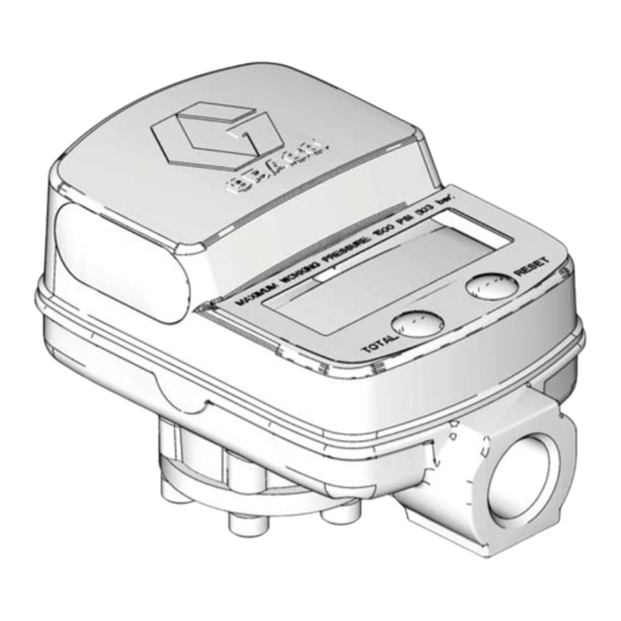
SDI15
Electronic Meter
Used to measure the quantify of dispensed fluid. Not approved to European explosive
atmosphere requirements or for use in hazardous locations. For indoor use only.
Model: 247453:
Use with petroleum-based
and synthetic oils and antifreeze only.
1500 psi (10.3 MPa, 103 bar) Maximum Working Pressure
15 gpm (57 lpm) Maximum Flow Rate
Model: 24G738:
only.
1500 psi (10.3 MPa, 103 bar) Maximum Working Pressure
15 gpm (57 lpm) Maximum Flow Rate
Important Safety Instructions
Read all warnings and instructions in this
manual. Save these instructions.
Inline
Use with diesel exhaust fluid
313048D
EN
ti12832a
Advertisement
Table of Contents

Related Manuals for Graco SDI15


Summary of Contents for Graco SDI15
- Page 1 Instructions ® SDI15 Inline Electronic Meter 313048D Used to measure the quantify of dispensed fluid. Not approved to European explosive atmosphere requirements or for use in hazardous locations. For indoor use only. Model: 247453: Use with petroleum-based and synthetic oils and antifreeze only.
-
Page 2: Fire And Explosion Hazard
Warnings Warnings The following warnings are for the setup, use, grounding, maintenance, and repair of this equipment. The exclama- tion point symbol alerts you to a general warning and the hazard symbol refers to procedure-specific risk. Refer back to these warnings. Additional, product-specific warnings may be found throughout the body of this manual where applicable. -
Page 3: Personal Protective Equipment
Warnings SKIN INJECTION HAZARD High-pressure fluid from dispensing device, hose leaks, or ruptured components will pierce skin. This may look like just a cut, but it is a serious injury that can result in amputation. Get immediate surgical treatment. • Engage trigger lock when not dispensing. •... -
Page 4: Installation
Installation Installation Grounding Pressure Relief Procedure The equipment stays pressurized until pressure is The equipment must be grounded. relieved. To reduce the risk of serious injury from pressurized fluid, accidental spray from the To reduce the risk of static sparking, ground all system dispenser or splashing fluid, follow the Pressure components per local and national electrical codes. -
Page 5: Typical Installation
The meter must be installed in-line as part of a dispense system as shown in F . 1. The typical installation shown is only a guide for selecting and installing an in-line meter; it is not an actual system design. Contact your Graco distrib- utor for assistance in designing a system to suit your needs. - Page 6 Meter Setup and Operation Meter Setup and Operation Setup Keypad Keys (F . 3) Terms The following terms are shown on the display and/or used often in this instruction manual. • R-TOTAL: Resettable Total Shows the cumulative amount that has been dis- pensed.
- Page 7 Meter Setup and Operation Displaying Setup Menus The amount displayed can be reset to zero at any time from the setup menus. * Press and hold Reset and Non-resettable Total Total keys simultaneously to display meter setup menus. The Non-resettable Total (displayed when TOTAL is on the screen as shown in F .
- Page 8 Meter Setup and Operation 1. Press and hold both the TOTAL and RESET keys. into the meter (F . 9). The All Segments screen and then the Software Version screen shown in F . 7 display. NOTE: The last two numeric digits of the number displayed on the Software Version screen reflect the version of software your meter is using.
- Page 9 Meter Setup and Operation MODEL 24G738: A one quart (US) or one liter (metric) Weights and Mea- sures approved container is required for calibration. This meter is factory calibrated to dispense water at 70°F (21°C) at 2.5 gpm (9.5 lpm). .
-
Page 10: Battery Replacement
Service Service Battery Replacement Graco recommends using AA Alkaline batteries such as 3. Use your fingers to pull battery cover (16) out of meter housing (1). Be careful not to lose the gasket ® ® ® ® Duracell , Energizer... -
Page 11: Troubleshooting
Troubleshooting Troubleshooting Problem Cause Solution Battery icon is shown on the display Batteries are low Replace batteries (5). See Replac- ing Battery, page 10. Replacement battery information is also provided in Technical Data, page 13. Digital display does not activate Batteries are low Replace batteries (5). -
Page 12: Display Lcd
113412 SCREW, mach, torx pan hd COVER, metering chamber SCREW, cap 15M432 COVER, battery 15M920 SCREW, seal, pan hd DISPLAY, LCD 109072 PACKING, o-ring Only parts that include a part number are available from Graco. All others are provided for reference only. 313048D... -
Page 13: Technical Data
Technical Data Technical Data Model 247453 Model 24G738 0.5 to 15 gpm 0.5 to 15 gpm Flow range (1.9 to 57 lpm) Flow Range (1.9 to 57 lpm) 1500 psi (10.3 MPa, 103 1500 psi (10.3 MPa, 103 Maximum working pressure bar) Maximum working pressure bar) -
Page 14: Graco Standard Warranty
With the exception of any special, extended, or limited warranty published by Graco, Graco will, for a period of twelve months from the date of sale, repair or replace any part of the equipment determined by Graco to be defective.
Need help?
Do you have a question about the SDI15 and is the answer not in the manual?
Questions and answers