Table of Contents
Advertisement
Quick Links
INSTRUCTIONS
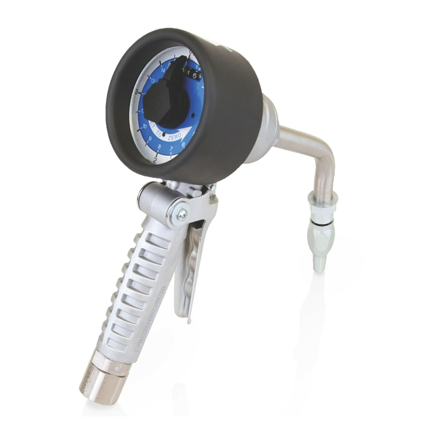
SDMM8 Manual Meter and
SDMP8 Preset Meter
For metered dispense of petroleum-based lubricants, oils and 50:50 antifreeze/water mix
fluids only.
For professional use only.
Maximum Working Pressure: 1500 psi (10 MPa, 103 bar)
List of Models page 2
Important Safety Instructions
Read all warnings and instructions in this
manual. Save these instructions.
333492G
EN
Advertisement
Table of Contents

Related Manuals for Graco SDMM8


Summary of Contents for Graco SDMM8
- Page 1 INSTRUCTIONS SDMM8 Manual Meter and SDMP8 Preset Meter 333492G For metered dispense of petroleum-based lubricants, oils and 50:50 antifreeze/water mix fluids only. For professional use only. Maximum Working Pressure: 1500 psi (10 MPa, 103 bar) List of Models page 2...
- Page 2 4/16 Liter BSPT 24U958* 4/16 Liter BSPP SDMM8 Manual Meters with Nozzle and Extension Packages The following packages include Bare Meter Model 24U959 and the nozzle and extension kits indicated in the table below. Model Number Model Description Inlet Extension Nozzle/Extension Kit...
- Page 3 Models The following packages include Bare Meter Model 24U957 and the nozzle and extension kits indicated in the table below. Model Number Model Description Inlet Extension Nozzle/Extension Kit Nozzle Parts† 24V044 4/16 Liter BSPT Flex 255853 255459 24V047 4/16 Liter BSPT Rigid 255852...
- Page 4 Models SDMP8 Preset Meters with Nozzle and Extension Packages The following packages include Bare Meter Model 24U947 and the nozzle and extension kits indicated in the table below. Model Number Model Description Inlet Extension Nozzle/Extension Kit Nozzle Parts† 24V052 60 Quart Rigid 24W641 255459...
- Page 5 Models The following packages include Bare Meter Model 24U954 and the nozzle and extension kits indicated in the table below. Model Number Model Description Inlet Extension Nozzle/Extension Kit Nozzle Parts† 24V059 60 Liter BSPT Rigid 24W641 255459 The following packages include Bare Meter Model 24U955 and the nozzle and extension kits indicated in the table below.
- Page 6 Warnings Warnings The following warnings are for the setup, use, grounding, maintenance, and repair of this equipment. The exclama- tion point symbol alerts you to a general warning and the hazard symbols refer to procedure-specific risks. When these symbols appear in the body of this manual or on warning labels, refer back to these Warnings. Product-specific hazard symbols and warnings not covered in this section may appear throughout the body of this manual where applicable.
- Page 7 Warnings WARNING WARNING WARNING WARNING EQUIPMENT MISUSE HAZARD Misuse can cause death or serious injury. • Do not operate the unit when fatigued or under the influence of drugs or alcohol. • Do not exceed the maximum working pressure or temperature rating of the lowest rated system component.
-
Page 8: Typical Installation
Pressure relief valve (required) NOTE: The relief pressure cannot exceed the meter’s maximum working pressure Fluid shut off valve Fluid line Fluid shut off valve Hose reel SDMM8 or SDMP8 meter Mounting channel Hose reel fluid inlet kit Fluid drain valve 333492G... -
Page 9: Installation
SDMM8 and SDMP8 Meter (N): When installing the meter leave at least two threads bare when using thread sealant. The bare threads ensure a ground is main- tained. -
Page 10: Component Identification
Installation Component Identification Key: Swivel 12 Trigger 37 Meter dial 41 Meter pointer 101 Nozzle 102 Extension 333492G... -
Page 11: Pre-Installation Procedure
Installation Pre-Installation Procedure 4. Slowly open the fluid shut off valve (J). 5. If you have multiple dispense positions, first flush NOTE: The letters used in the following instructions the dispense position farthest from the pump and refer to Typical Installation on page 8 and the Compo- work your way toward the pump. - Page 12 Installation 4. Install extension (102) to meter: d. Wrench tighten extension nut (102a). a. Loosen extension nut (102a) (F . 4) until it is 5. Install nozzle (101): completely off tube threads. NOTE: Do not use PTFE tape or thread sealant on threads of nozzle (101).
-
Page 13: Operation
Operation Operation The totalizer keeps a running total of the amounts dis- pensed. NOTE: The letters used in the following instructions 1. Turn meter pointer (41) counter-clockwise to select refer to Typical Installation on page 8 and the Compo- the desired volume. nent Identification on page 10. -
Page 14: Troubleshooting
Fluid shut-off valve (J or L) is not fully open Fully open fluid shut-off valve (J or L). (page 10). Foreign material is wedged in the meter Contact your Graco distributor for repair housing. or replacement. Meter leaks from twist lock nozzle. - Page 15 Troubleshooting Problem Cause Solution Poor swivel/hose connection. Apply PTFE tape (leave a minimum 2 engaged threads uncovered for electri- cal continuity) or sealant to threads of hose and tighten the connection. See Step 2 in Installation Procedure, page Meter leaks from swivel. Poor swivel/meter housing connection.
- Page 16 9. Install cover (17) on meter housing. Torque to 11-14 ft. lbs (14.9-18.9 N•m). 10. Install nozzle and extension assembly (101 and 102). SDMM8 Manual Meter Counter Section Repair Disassembly . 11 NOTE: Do not disassemble the fluid and counting sec- 5.
- Page 17 Service 4. Use a hex wrench to remove the plug setscrew. Remove the plug (50), remove the pin (51), spring (53), and the lower pointer (52) (F . 16). 1. Relieve pressure, page 9. 2. Remove the cover (44), small retaining ring (43), pointer pin (41) and pointer spring (42) (F .
- Page 18 Service 7. Remove the entire counter assembly (31) (F . 19). 3. Install the face plate panel (37) and large retaining clip (38) (F . 22). . 19 . 22 Reassembly 4. Install the lower pointer (52), spring (53), pin (51) and plug (50) as shown in F .
- Page 19 Service 6. Install small retaining ring (43), pointer pin (41) and 3. Remove the needle pointer (41), springs (39) and pointer spring (42). Install the cover (44). (F . 25). pins (40) (F . 27). 39/40 . 25 . 27 4.
- Page 20 Service 6. Remove the entire counter assembly (31) (F . 30). 3. Install face plate panel (37) and large retaining clip (38) (F . 33). . 30 Reassembly . 33 1. Install counter assembly (31) (F . 31). 4. Install the needle pointer (41), springs (39) and pins (40) as shown in F .
-
Page 21: Technical Data
Technical Data Technical Data Manual and Preset Meter Metric Flow rate* 0.26 to 8 gpm 1 to 30 lpm Maximum working pressure 1500 psi 10 MPa, 103.4 bar Weight Manual Meter 3.42 lbs 1.55 kg Preset Meter 3.50 lbs 1.58 kg Dimensions (without extension) (see page 29) Length 11.4 inches... - Page 22 SDMM8 Manual Meter Parts SDMM8 Manual Meter Parts Models 24U959, 24U960, 24U961, 24U956, 24U957, 24U958 Ref A Ref B Ref B See Ref A 3b 3a Torque to 7-10 ft lbs (9-13 N.m) Torque to 15-25 in. lbs (1.7-2.8 N.m) Torque to 11-14 ft.
- Page 23 SDMM8 Manual Meter Parts SDMM8 Manual Meter Parts Models 24U959, 24U960, 24U961, 24U956, 24U957, 24U958 Part No. Description Part No. Description GEAR, 21 teeth SWIVEL 24V467 KIT, SHAFT 238399 model 24U959, 24U956 106560 PACKING, o-ring 24H383 model 24U960, 24U957 24U352...
- Page 24 SDMP8 Preset Meter Parts SDMP8 Preset Meter Parts Models 24U947, 24U948, 24U949, 24U950, 24U951, 24U952, 24U953, 24U954, 24U955 Ref A Ref B Ref B Ref A 9 10 11 Torque to 7-10 ft lbs (9-13 N.m) Torque to 15-25 in. lbs (1.7-2.8 N.m) Torque to 11-14 ft.
- Page 25 SDMP8 Preset Meter Parts SDMP8 Preset Meter Parts Models 24U947, 24U948, 24U949, 24U950, 24U951, 24U952, 24U953, 24U954, 24U955 Part No. Description Part No. Description PISTON, oscillating SWIVEL DIVIDER 238399 model 24U947, 24U950, 24U953 PISTON, chamber 24H383 model 24U948, 24U951, ROLLER (not shown) 24U954 GEAR, 10 teeth 24H382...
- Page 26 SDMP8 Preset Meter Parts Part No. Description Part No. Description 16X587 GEAR, twin 11-44 teeth 41 16X577 NEEDLE (not shown) Models 42 16X584 SPRING, outer pointer 24U947, 24U948, 24U949, 24U953, 24U954, 24U955 RING, retaining 16Y999 GEAR, twin 24-44 teeth 43a 16X611 (not shown) Models 43b...
- Page 27 Nozzle (101) and Extension (102) Kits Nozzle (101) and Extension (102) Kits Kit No. Description Fluid Type Automatic, non-drip quick close nozzle with 255852* rigid extension Automatic, non-drip quick close nozzle with 255853* flexible extension Automatic, non-drip quick close nozzle with short rigid extension 24W641* Non-drip, quick close nozzle with rigid...
- Page 28 Nozzle (101) Parts Nozzle (101) Parts Part No. Description Fluid Type 255459* Automatic, non-drip, quick-close nozzle • BODY, nozzle • O-RING, packing • SPRING, compression • O-RING, packing • STEM, nozzle, valve • SEAT, valve 255460* Automatic, non-drip, quick-close nozzle Antifreeze •...
- Page 29 Nozzle (101) Parts Dimensions Manual Meter Preset Meter . 37 . 36 333492G...
- Page 30 With the exception of any special, extended, or limited warranty published by Graco, Graco will, for a period from the date of sale as defined in the table below, repair or replace equipment covered by this warranty and determined by Graco to be defective.
Need help?
Do you have a question about the SDMM8 and is the answer not in the manual?
Questions and answers