Table of Contents
Advertisement
Quick Links
Instructions - Parts
Helical Gear
Fluid Flow Meters
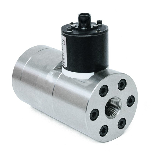
Positive displacement helical gear flow meters designed for higher flow rates and higher
viscosity materials. For professional use only.
Not approved for use in European explosive atmosphere locations.
6000 psi (41 MPa, 410 bar) Maximum Fluid Working Pressure
See page 2 for a list of models.
Important Safety Instructions
Read all warnings and instructions in this
manual. Save these instructions.
HG6000 Meter Shown
309834W
EN
r_246190_309834_1r
0359
Advertisement
Table of Contents

Related Manuals for Graco HG6000


Summary of Contents for Graco HG6000
- Page 1 Not approved for use in European explosive atmosphere locations. 6000 psi (41 MPa, 410 bar) Maximum Fluid Working Pressure See page 2 for a list of models. HG6000 Meter Shown Important Safety Instructions Read all warnings and instructions in this manual.
-
Page 2: Table Of Contents
Flushing the Meter ..... . . 9 Graco Information ......20 Disassembly . -
Page 3: Warnings
Equipment misuse can cause the equipment to rupture or malfunction and result in serious injury. • This equipment is for professional use only. • Use the equipment only for its intended purpose. Call your Graco distributor for information. • Read all instruction manuals, tags, and labels before operating equipment. •... - Page 4 Warnings WARNING SKIN INJECTION HAZARD Spray from the gun, leaks, or ruptured components can inject fluid into your body and cause extremely serious injury, including the need for amputation. Fluid splashed in the eyes or on the skin can also cause serious injury.
-
Page 5: Installation
Installation Installation Installing the Flow Meter • Flow volume can only be measured at the location where the flow meter is installed. Dust and Foreign Matter • Do not use more than 200 ft. (61 m) of cable. Avoid having dust or foreign matter enter the flow meter •... -
Page 6: Grounding
Installation Grounding 2. Never use the flow meter with an electrostatic gun isolation stand. Sensor Connector Pin-out 1. Always ground the fluid supply unit, using one of the following options: Pin 1: +10-30 Vdc Supply Pin 2: Signal Out a. Mount the meter to a grounded conductive sur- Pin 3: Ground face, or Pin 4: No Connection... -
Page 7: Operation
Operation Operation Flow Meter Verification The factory calibration factor (k factor) for the flow meter is stated in the Technical Data section of the manual. Pressure Relief Procedure This calibration factor is the number of flow meter pulses per liter, as determined by a measurement with oil. 1. -
Page 8: Troubleshooting
Troubleshooting Troubleshooting The sensor is not a serviceable part. Replace it if it is malfunctioning. Problem Cause Solution No flow volume displayed at monitor- Flow volume is too low to measure Increase flow volume. ing unit Fluid is not flowing See Problem: Fluid is not flowing, below. -
Page 9: Maintenance
Maintenance Maintenance 4. Follow the Pressure Relief Procedure, then dis- connect the fluid line from the solvent supply unit. 5. Reconnect the fluid line to the fluid supply. 6. Turn on the fluid supply. CAUTION Do not immerse the meter in solvent with the electronic 7. -
Page 10: Assembly
Maintenance 5. Hold the end housing (1) and gently alternately tap 7. Insert the 3-tooth helical gear (8) into the gear bear- on the two screws (2) with a hammer to separate ing (5), making sure the two helical gears mesh with the middle housing (11). -
Page 11: Parts
Parts Parts Model 246190, HG6000 Meter r_246190_309834_3r Torque to 350 +/- 15 in-lb (39.5 +/- 1.7 N•m) Torque to 42 +/- 15 in-lb (4.75 +/- 1.7 N•m) After ball (6) is placed into bearings, apply grease (31) into bearing area. -
Page 12: Model 280560, Hg6000 Meter
Parts Model 280560, HG6000 Meter r_246190_309834_3r Torque to 350 +/- 15 in-lb (39.5 +/- 1.7 N•m) Torque to 42 +/- 15 in-lb (4.75 +/- 1.7 N•m) After ball (6) is placed into bearings, apply grease (31) into bearing area. Ref. -
Page 13: Part No. 15V820 Helical Gear Fluid Flow Meter Assembly
Description Qty. Ref. Part Description Qty. 117670 BRACKET, mounting 280560 METER, HG6000; see page 12 115226 WASHER, lock; M6 15M861 REDUCER, pipe; 3/4 npt(m) x 1/4 107530 SCREW, cap, socket head; M6 x npt(f) 12 mm 166846 ADAPTER; 1/4 npt x 1/4 npsm 108328 SCREW, cap, socket head;... -
Page 14: Model 246340, Hg6000Ht Meter And Model 24R174, Hg6000Ht-Fm Meter
Parts Model 246340, HG6000HT Meter and Model 24R174, HG6000HT-FM Meter 7d 7f Torque to 350 +/- 15 in-lb (39.5 +/-1.7 N•m) r_246340_309834_1p Torque to 45 +/- 15 in-lb (5.09 +/- 1.7 N•m) Apply thermal lubricant (45) After ball (6) is placed into bearings, apply grease (52) into bearing area. - Page 15 Parts Model 246340, HG6000HT Meter and Model 24R174, HG6000HT-FM Meter Ref. Part Description Qty. Ref. Part Description Qty. 15B773 INSERT, threaded; m8 HOUSING, end 102235 SCREW, cap, hex head 117535 SCREW, cap, socket head 115862 CONNECTOR, male, crimp GUIDE, gear 115861 BULKHEAD, housing, insulat- 4†...
-
Page 16: Model 246652, Hg6000Hr Meter And Model 24P688, Hg6000Hr-Fm Meter
Parts Model 246652, HG6000HR Meter and Model 24P688, HG6000HR-FM Meter r_246652_309834_1l Torque to 350 +/- 15 in-lb (39.5 +/- 1.7 N•m) Torque to 42 +/- 15 in-lb (4.75 +/- 1.7 N•m) After ball (6) is placed into bearings, apply grease (31) into bearing area. Ref. -
Page 17: Dimensions
Dimensions Dimensions Flow Meter Port Size 3.0 in. 5.6 in. 76.2 mm 142.2 mm 6.1 in. 154.9 mm 3/4 - 14 npt(f) Outlet 3/4 - 14 npt(f) Inlet Flow Meter Mounting Holes Flow Meter Mounting Holes 2.1 in. (TOP VIEW) (BOTTOM VIEW) (53.3 mm) 1.0 in. -
Page 18: Technical Data
However, the Flow Range may be different depending on the Graco system in which the Flow Meter is used. To find the Flow Range for a specific Graco system, refer to that system's Operation Manual. -
Page 19: Accessories
0.25 0.50 0.00 Flow Rate (GPM) Accessories Use Only Genuine Graco Parts and Accessories Fluid Filter C58997 (30 mesh) High Resolution Meter Sensor Replacement Kit 246786 5000 psi (350 bar) Maximum Working Pressure The sensor update has been made to meters 246190... -
Page 20: Graco Standard Warranty
With the exception of any special, extended, or limited warranty published by Graco, Graco will, for a period of twelve months from the date of sale, repair or replace any part of the equipment determined by Graco to be defective. This warranty applies only when the equipment is installed, operated and maintained in accordance with Graco’s written recommendations.
Need help?
Do you have a question about the HG6000 and is the answer not in the manual?
Questions and answers