Table of Contents
Advertisement
Quick Links
Instructions-Parts
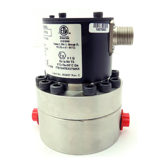
Volumetric Fluid Flow
Meter
For precise metering, with models for plural component fluids or solvents.
For professional use only.
See page 3 for model information, including maximum working pressure.
Important Safety Instructions
Read all warnings and instructions in this
manual before using the equipment.
Save these instructions.
G3000, G3000A, and G3000HR
FX250
S3000 Solvent Meter
TI11579a
G250 and G250HR
308778ZAG
EN
TI14674b
TI13038a
Advertisement
Table of Contents

Related Manuals for Graco FX250


Summary of Contents for Graco FX250
- Page 1 See page 3 for model information, including maximum working pressure. Important Safety Instructions Read all warnings and instructions in this manual before using the equipment. Save these instructions. S3000 Solvent Meter G3000, G3000A, and G3000HR TI11579a TI14674b G250 and G250HR FX250 TI13038a...
-
Page 2: Table Of Contents
Graco Standard Warranty ....24 Graco Information ......24... -
Page 3: Meter Models
0.02 to 1.0 gpm (75 to 3800 cc/min) 249427 G250HR 24W651 0.01 to 0.5 gpm (38 to 1900 cc/min) FX250* FX250 0.02 to 1.0 gpm (75 to 3800 cc/min) * See the Iniflex manual (3A8637) for model configurations. High Pressure Fluid Meters 4000 psi (28 MPa, 280 bar) Maximum Fluid Working Pressure Meter Part No. -
Page 4: Warnings
Warnings Warnings The following warnings are for the setup, use, grounding, maintenance, and repair of this equipment. The exclamation point symbol alerts you to a general warning and the hazard symbols refer to procedure-specific risks. When these symbols appear in the body of this manual, refer back to these Warnings. Product-specific hazard symbols and warnings not covered in this section may appear throughout the body of this manual where applicable. - Page 5 Warnings WARNING SPECIFIC CONDITIONS OF USE Equipment must comply with the following conditions to avoid a hazardous condition which can cause fire, explosion, or electric shock: • Sensor housing is of aluminum construction. Precautions must be taken to avoid impacts or contact with moving parts.
- Page 6 Warnings WARNING TOXIC FLUID OR FUMES HAZARD Toxic fluids or fumes can cause serious injury or death if splashed in the eyes or on skin, inhaled, or swallowed. • Read Safety Data Sheets (SDSs) to know the specific hazards of the fluids you are using. •...
-
Page 7: Installation
Installation Installation Installing the Flow Meter NOTE: You must assemble the meter sensor to the meter body before connecting the cable to the sensor Improper wiring can cause fire and explosion, electric for the meter to function properly. shock, or other serious injury. •... -
Page 8: Intrinsically Safe Installation Requirements
Installation Intrinsically Safe Installation 5. For ATEX and UK Ex, install per EN 60079-14 and applicable local and national codes. Requirements 6. Cable used to connect sensor and safety barrier See F . 2. must take capacitance and inductance into account. The maximum capacitance of the barrier is to be 1. -
Page 9: Grounding
Installation Grounding 2. Always ground the meter, using one of the following options: a. Mount the meter to a grounded conductive The equipment must be grounded to reduce the risk surface, or of static sparking and electric shock. Electric or static sparking can cause fumes to ignite or explode. -
Page 10: Operation
Operation Operation Pressure Relief Procedure Flow Volume Range The G3000v G3000A, G250, and FX250 meters flow Follow the Pressure Relief Procedure whenever volume range is 0.02-1.0 gal./min. (75-3800 cc/min.). you see this symbol. The G3000HR and G250HR meters flow volume range is 0.01-0.5 gal./min. -
Page 11: Troubleshooting
Troubleshooting Troubleshooting Follow Pressure Relief Procedure, page 10, before checking or repairing the equipment. NOTE: The sensor is not a serviceable part. Replace it if it is malfunctioning. Problem Cause Solution No flow volume displayed at Flow volume is too low to measure. Increase flow volume. -
Page 12: Maintenance
Maintenance Maintenance Flush the Equipment Improper wiring can cause fire and explosion, electric shock, or other serious injury. • Disconnect power source before installing. • All electrical equipment must only be installed by a qualified electrician. To avoid fire and explosion, always ground equipment •... -
Page 13: Cleaning Or Servicing The Meter Chamber
10. Assemble the two meter housings, making sure to Use only genuine Graco replacement parts. keep them parallel to each other. Substitution of components may impair intrinsic 11. Install the screws. Tighten them oppositely and safety. -
Page 14: Cleaning Or Servicing The Solvent Meter
(3d). Remove the shims trained and qualified. (3c). Use only genuine Graco replacement parts. NOTE: Do not remove the gear shafts (S) or the gear Substitution of components may impair intrinsic bearings (B). -
Page 15: Parts
Parts Parts Flow Meter Kits, for ProMix 2KS Wall Fluid Panel 15V804 G3000 Meter Kit 280555 S3000 Solvent Meter Kit 826212 G3000A Meter Kit 15V827 G3000HR Meter Kit TI14676b Ref. Part Description TI12427a 258718 METER, gear, S3000; used on Ref. Part Description 280555;... -
Page 16: Bare Meter Assemblies
Parts Bare Meter Assemblies 289813 G3000 Meter 26A119 G3000A Meter 289814 G3000HR Meter Ref. Part No. Description Qty. 114100 SCREW, socket-hd; M4 x 55 mm long 24W651 ELECTRONIC SENSOR** 239719 GEAR METER ASSEMBLY; includes items 4-11; used on 289813 26A118 GEAR METER ASSEMBLY;... - Page 17 Parts 249426 G250 Meter 249427 G250HR Meter FX250 Meter Ref. Part No. Description Qty. 111308 SCREW, cap, socket-hd HOUSING, upper 110588 O-RING; ptfe 239718 GEAR; used on 249426 244290 GEAR; used on 249427 192383 SHAFT, gear† 197142 SHAFT, gear‡ 192387 PIN, locating...
-
Page 18: Solvent Meter Assembly
Parts Solvent Meter Assembly 258718 S3000 Meter Ref. Part No. Description Torque to 27-57 in-lb (3.1-6.4 N•m). 114100 SCREW, socket-hd; M4 x 55 mm Torque to 11 ft-lb long (15 N•m). 24W650 ELECTRONIC SENSOR** 24G951 GEAR METER ASSEMBLY; used on 258718; includes items 3a-3f SCREW;... - Page 19 3.75 in. (95.25 mm) 1/4-18 npt(f) 4.00 in. inlet/outlet 1.92 in. (101.6 mm) (48.77 mm) 2.16 in. 1/4-18 npt(f) (54.86 mm) inlet/outlet 2.47 in. (62.74 mm) TI13042a 2.97 in. (74.44 mm) TI11579a FX250 Part No. FX250 Mounting Holes (bottom view) 308778ZAG...
-
Page 20: Dimensions
Dimensions Solvent Meter Part No. 258718 Mounting Holes (bottom 3.71 in. 1/4-18 npt(f) 2.36 in. (94.2 mm) inlet/outlet (60 mm) 1.96 in. (49.8 mm) 1.75 in. (44.45 mm) 3.15 in. TI14680a (80 mm) TI14674b Kit Mounting Bracket Part No. 15U749 0.44 in. -
Page 21: Technical Specifications
Technical Specifications Technical Specifications Volumetric Fluid Flow Meters U.S. Metric Maximum Fluid Working Pressure G3000, G3000A, and G3000HR 4000 psi 28 MPa, 276 bar S3000 Solvent Meter 3000 psi 21 MPa, 210 bar G250 and G250HR 300 psi 2.1 MPa, 21 bar Flow Range G3000, G3000A, and G250 0.02-1.0 gal/min... -
Page 22: California Proposition 65
California Proposition 65 308778ZAG... -
Page 23: Pressure Drop Curve
Pressure Drop Curve Pressure Drop Curve 500 cps 400 cps 300 cps 200 cps 100 cps 50 cps G3000/G3000A gal/min G250 and FX250 0.40 G3000HR/G250HR 0.05 0.10 0.15 0.20 0.25 0.30 0.35 0.45 0.50 0.55 gal/min 0.16 S3000 0.025 0.05 0.065 0.076 0.083 0.10... -
Page 24: Graco Standard Warranty
With the exception of any special, extended, or limited warranty published by Graco, Graco will, for a period of twelve months from the date of sale, repair or replace any part of the equipment determined by Graco to be defective.
Need help?
Do you have a question about the FX250 and is the answer not in the manual?
Questions and answers