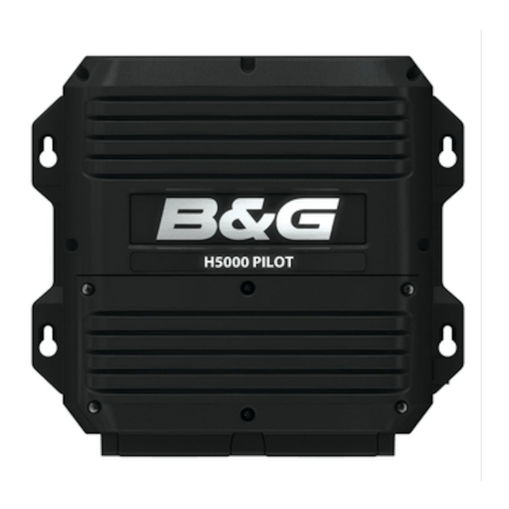
B&G H5000 Installation Manual
Pilot computer
Hide thumbs
Also See for H5000:
- Operation manual (117 pages) ,
- Installation manual (66 pages) ,
- Advanced user information (18 pages)
Table of Contents
Advertisement
Quick Links
H5000 PILOT COMPUTER
INSTALLATION GUIDE
For product manuals, technical specifica ons,
cer ficates and declara ons,
refer to the product website on:
www.bandg.com
*988-10673-001*
Parts included
1
2
3
5
4
1
1 x H5000 Pilot Computer
2
4 x Fixing screws, 3.5 * 19 mm
3
1 x Micro-C Drop cable (male)
4
1 x Micro-C T-Joiner
5
6 x Connectors
6
1 x 30 Amp fuse
Mounting
Dimensions
6
System wiring
1
5
T
6
12V
7
1
5
Masthead Unit
2
Graphic Display
6
3
H5000 Pilot Controller
7
4
8
GPS Antenna
92.0 mm (3.62")
196.0 mm (7.72")
2
3
12V
9
12V
8
9
Micro-C CAN bus backbone
H5000 Pilot Computer
H5000 Computer Unit
10
Rudder Feedback Unit
Speed sensor
11
Compass
12
Depth sensor
Hydraulic Ram
65.5 mm (2.58")
4
T
11
10
12
T
Terminator
12V
12 Volts
Advertisement
Table of Contents

Subscribe to Our Youtube Channel
Summary of Contents for B&G H5000
-
Page 1: H5000 Pilot Computer
Parts included Dimensions H5000 PILOT COMPUTER INSTALLATION GUIDE 1 x H5000 Pilot Computer 4 x Fixing screws, 3.5 * 19 mm 1 x Micro-C Drop cable (male) 1 x Micro-C T-Joiner 6 x Connectors 92.0 mm (3.62") 65.5 mm (2.58") 1 x 30 Amp fuse 196.0 mm (7.72") -
Page 2: External Alarm
H5000 Pilot Computer ne peut pas commander des électrovannes sans utiliser un relais isolé. H5000 Pilot Computer kann keine extern gespeisten Magnetventile ansteuern sofern keine isolierten Relais installiert sind. H5000 Pilot Computer kan ikke kobles mot magnetventiler med eksternt tilført spenning uten at man benytter eksterne releer. Power supply...


Need help?
Do you have a question about the H5000 and is the answer not in the manual?
Questions and answers