Table of Contents
Advertisement
Quick Links
Advertisement
Table of Contents

Related Manuals for B&G HB-1000I


Summary of Contents for B&G HB-1000I
- Page 1 HB-1000I Issue: 0001...
-
Page 2: Index
h1000 pilot index index index h1000 pilot display description siting the pilot head mounting procedure panel mounting h1000 compass unit description siting the compass unit mounting procedure rudder reference unit (rru) description key points when installing the rru linear feedback unit rudder drive options ram drive unit description... -
Page 3: Table Of Contents
h1000 pilot index index hydraulic drive pump installation examples single station system example dual station system example dual station system with bypass example dual station pressurised system example advanced control processor unit (acp) description siting the acp mounting procedure cable and connection information emc compliance general wiring notes all rudder drives –... - Page 4 h1000 pilot index index h1000 pilot calibration pilot installation checklist drive unit and steering system linear hydraulic rams size 3 ram installation checklist hydraulic pumps rotary drives rudder reference unit installation linear feedback unit installation compass installation electronics installation speed calibration calibrating the pilot pilot calibration parameters dockside calibration...
-
Page 5: H1000 Pilot Display
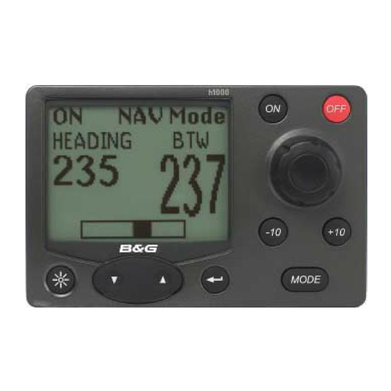
h1000 pilot description/installation h1000 pilot display d e s c r i p t i o n d e s c r i p t i o n The h1000 pilot display is designed to be mounted above or below decks. The display head allows control of the pilot and by installing multiple display heads, gives control at any station. -
Page 6: Mounting Procedure
h1000 pilot description/installation mounting procedure panel mounting Ensure there is sufficient room behind the panel to accommodate the fixings and connections, and using the template supplied, cut a hole in the panel in the desired position. Fix the mounting bracket into the hole using the screws supplied. Note: The sealing ring is fitted to the unit during manufacture, it purpose is to prevent moisture penetration and reduce the effects of any vibration transmitted through the instrument panel. -
Page 7: H1000 Compass Unit
h1000 pilot description/installation h1000 compass unit description The h1000 compass is an electronic fluxgate for use with all h1000 systems. The unit is housed in a sealed casing constructed of high impact plastic. It is therefore suitable for on or below deck mounting. If installed in a vessel with a steel or reinforced concrete hull it may be necessary to install the compass unit outside the magnetic screening affect of the hull and super-structure. -
Page 8: Rudder Reference Unit (Rru)
h1000 pilot description/installation rudder reference unit (rru) description The Rudder Reference Unit (rru) is a sealed, high specification potentiometer in a robust casing, providing rudder position information to the pilot computer unit. The operating arm is constructed from aluminium with three positions pre-drilled for the adjustable drag-link. The drag-link has ball-joints at each end which connect the unit operating arm to the tiller arm or steering quadrant. - Page 9 h1000 pilot description/installation rudder reference unit Measure the voltage difference between the green and blue wires of the rru; there should be a minimum of 1volt change from hardover to hardover. Note: If there is less than a 1volt change the pilot will not commission. •...
- Page 10 h1000 pilot description/installation rudder reference unit Page 9...
- Page 11 h1000 pilot description/installation rudder reference unit The RRU can be mounted in a variety of positions and orientations depending on the layout of the steering system. If the maximum rudder angle is less than 90° then the position of the RRU or the drag-link must be adjusted so that the operating arm of the RRU swings through a minimum of 90.
-
Page 12: Linear Feedback Unit
h1000 pilot description/installation rudder reference unit The rudder hardover angle should only be limited by the rudder stops, not the rru linkage or pilot drive unit. Check that when hardover, the rru arm and drag-link do not form a straight line. If this occurs the steering system could become damaged or jammed endangering the boat and crew. -
Page 13: Rudder Drive Options
h1000 pilot description/installation rudder drive options ram drive unit description A hydraulic pump driven from the dc electric supply combines compact reversible pump and a hydraulic cylinder assembly for use on boats without hydraulic steering systems. Three sizes of ram drive units are available giving a wide range of thrust to suit all vessel types and sizes. - Page 14 h1000 pilot description/installation rudder drive options The following table may be used to determine the steering system geometry for different maximum rudder angles and ram type. The last three columns show the peak torque available (in Kgm), amidships position and at the maximum rudder angle. The latter two are shown with the motor running at 50% duty cycle.
-
Page 15: Hydraulic Ram Drive Dimensions (T1-12V, T2-12V, T2-24V)
h1000 pilot description/installation hydraulic ram drive dimensions (T1-12V, T2-12V, T2-24V) Page 14... -
Page 16: Size 3 Hydraulic Ram Drive Dimensions, 24V
h1000 pilot description/installation size 3 hydraulic ram drive dimensions, 24V Page 15... -
Page 17: Ram Details
h1000 pilot description/installation ram details Page 16... -
Page 18: Ram Drive Unit Installation
h1000 pilot description/installation ram drive unit installation Note: General consideration must be given to the steering system and its geometry before starting the installation. Many factors must be contemplated for a practical solution; the information given here is for guidance only, although where a maximum or minimum value is given this must be adhered to. - Page 19 h1000 pilot description/installation layout of a typical ram drive unit b = tiller arm length a=half max rudder angle Page 18...
-
Page 20: Ram Mounted Parallel To Vessel's Centre-Line
h1000 pilot description/installation ram mounted parallel to vessel’s centre-line Page 19... -
Page 21: Key Points On Installation
h1000 pilot description/installation ram mounted parallel to vessel’s centre-line key points on installation • Make sure that the rudder angle is limited by the rudder stops and not the limit of travel of the ram arm. Failure to comply will damage the unit and invalidate the warranty. •... -
Page 22: Vertical Bulkhead Installation
h1000 pilot description/installation vertical bulkhead installation b= tiller arm ° ° a=half max rudder angle Page 21... -
Page 23: Splitting The Ram Drive Unit
h1000 pilot description/installation splitting the ram drive unit Note: when dealing with any hydraulic system great care must be taken to ensure that a high degree of cleanliness is observed and no dirt, moisture or foreign objects are allowed to enter the system. -
Page 24: Hydraulic Drive Pumps
h1000 pilot description/installation hydraulic drive pumps description The reversible hydraulic drive pump has a small high-speed pump driven by a 12V or 24V dc permanent magnet motor. The pump has pilot check valves to prevent back driving and a pilot operated reservoir valve to enable the unit to drive balanced or unbalanced cylinders. -
Page 25: Hydraulic Drive Pump Dimensions
h1000 pilot description/installation hydraulic drive pump dimensions type 1 and 2 105mm (4.13) 4 holesφ 7.0mm (0.28) 80mm (3.15) 240 m m (9.45) 88.9mm 50.8mm (3.5) (2.00) centres centres type 3 Page 24... -
Page 26: Hydraulic Drive Pump Installation
h1000 pilot description/installation hydraulic drive pump installation Note: : When dealing with any hydraulic system great care must be taken to ensure that a high degree of cleanliness is observed and no dirt, moisture or foreign objects are allowed to enter the system. -
Page 27: Hydraulic Drive Pump Installation Examples
h1000 pilot description/installation hydraulic drive pump installation examples s i n g l e s t a t i o n s y s t e m e x a m p l e s i n g l e s t a t i o n s y s t e m e x a m p l e d u a l s t a t i o n s y s t e m e x a m p l e d u a l s t a t i o n s y s t e m e x a m p l e Page 26... - Page 28 h1000 pilot description/installation hydraulic drive pump installation examples d u a l s t a t i o n s y s t e m w i t h b y p a s s e x a m p l e d u a l s t a t i o n s y s t e m w i t h b y p a s s e x a m p l e d u a l s t a t i o n p r e s s u r i s e d s y s t e m e x a m p l e...
-
Page 29: Description
h1000 pilot description/installation advanced control processor unit description The Advanced Control Processor (ACP) Unit contains all the electronics for the autopilot operation and control of the rudder drive options. It is designed to be mounted on a vertical, flat, smooth surface. The unit has a hinged lid to provide easy access to the electrical connections. -
Page 30: Cable And Connection Information
h1000 pilot description/installation acp unit installation cable and connection information emc compliance B&G equipment is designed to be operated in leisure craft. Every care has been taken in its design and testing to ensure compliance with the European EMC Directive, provided it is installed and operated in accordance with the instructions as supplied, and the units and cables used are unmodified. -
Page 31: Acp Unit Terminal Details
h1000 pilot description/installation pilot drive unit cables all rudder drives - heavy duty power cables Total Cable Length B&G Cable Copper Area Cable Gauge Part No. Up to 8m (26ft) 135-0A-128 4.0mm² 12 awg Up to 12m (40ft) Not available 6.0mm²... -
Page 32: Clutch Voltage Selection
h1000 pilot description/installation clutch voltage selection The h1000 pilot computer unit can output different clutch/solenoid voltages depending upon the size of rudder drive unit fitted. The clutch/solenoid valve is only required for rams or rotary drive units. This is achieved by setting dip-switches on the computer drive PCB. Access to the switches is obtained by removing the four screws holding the computer PCB into the lid of the computer unit and then carefully lifting the PCB clear. -
Page 33: Acp Dip Switch Location
h1000 pilot description/installation acp dip switch location Note: When reassembling the computer unit ensure that the connector in the top left-hand corner of the PCB mates correctly. Page 32... -
Page 34: H1000 And Alarm Connections
h1000 pilot description/installation h1000 and alarm connections h1000 h1000 MODE Red (+12v) Screen (0v) DRIVE DRIVE SUPPLY SUPPLY Alarm Unit 130-PK-10 Blue 12v alarm supply 1A Fuse Page 33... -
Page 35: Hand-Held, Mob And Joystick
h1000 pilot description/installation hand-held, mob and joystick DRIVE DRIVE SUPPLY SUPPLY Man Overboard Button (MOB) 302-00-007 Handheld Controller PLHH-ACP Joystick and Button 545-00-060 Page 34... -
Page 36: Hydraulic Ram Drive Connections
h1000 pilot description/installation hydraulic ram drive connections DRIVE DRIVE SUPPLY SUPPLY Heavy Duty Power Supply Black Rudder Reference Unit RRF-ACP Circuit Breaker Solenoid Connector Hydraulic Ram Drive RAM-T1-12V RAM-T2-12V RAM-T2-24V RAM-T3-24V Page 35... -
Page 37: Ram Solenoid Wiring Details
h1000 pilot description/installation ram solenoid wiring details the following information applies to the size 1, size 2 and size 3 blue rams only. 1. Remove the solenoid wiring connector by unscrewing the centre screw. 2. Remove the screw from the connector housing. 3. -
Page 38: Hydraulic Pump Connections
h1000 pilot description/installation hydraulic pump connections DRIVE DRIVE SUPPLY SUPPLY Heavy Duty Power Supply Black Rudder Reference Unit RRF-ACP Circuit Breaker Hydraulic Pump RAM-T1-12V RAM-T2-12V RAM-T3-24V Page 37... - Page 39 h1000 pilot description/installation continuous drive unit connections These are general wiring instructions only, showing the implementation of the ACP outputs to drive the continuous drive pump solenoid valves. The continuous drive pump motor will also require a heavy- duty supply, which is not provided. However, suitable units can be obtained from your dealer. Clutch output is used to control the motor supply.
-
Page 40: Direct Paddle Input Connection
h1000 pilot description/installation direct paddle input connection - + - + DRIVE DRIVE SUPPLY SUPPLY Cut back unused wires Please consult your dealer for the specific speed sensor and housing suitable for your vessel Page 39... -
Page 41: Linear Feedback Connection
h1000 pilot description/installation linear feedback connection When the linear feedback unit is used, connect the linear feedback unit to the h1000 pilot terminals using the reference table below. h1000 Processor Colours Function Linear Feedback Colours +5V Supply Blue 0V Supply Black Green Signal (Wiper) -
Page 42: Non-B&G Paddle Connection
h1000 pilot description/installation non-b&g paddle connection Any non-B&G speed sensor used with this system must have a speed signal output from a hall-effect device giving positive pulses of 12V maximum. Locate the cable from the speed sensor to the instrument input. Cut cable (if necessary) and insert a junction box (B&G part no. -
Page 43: Gyro Stabilized Compass Connection
h1000 pilot description/installation gyro stabilized compass connections DRIVE DRIVE SUPPLY SUPPLY Cut back unused wires 12v Gyro Compass Supply Blue Gyro Stabilized Compass Page 42... -
Page 44: Furuno Ad10 Heading Connection
h1000 pilot description/installation furuno ad10 heading connection - + - + DRIVE DRIVE SUPPLY SUPPLY Cut back unused wires Furuno AD10 Cable Furuno AD10 Compatible Display Page 43... -
Page 45: Hand-Held Controller
h1000 pilot optional devices hand-held controller d e s c r i p t i o n d e s c r i p t i o n The hand-held remote controller is a waterproof unit that has six function buttons and a status LED to indicate the operating mode of the autopilot. -
Page 46: Description
h1000 pilot optional devices man overboard button (mob) description The man overboard (MOB) button is a large, red, waterproof press-switch supplied with 15m (45ft) of two-core screened cable. Operation of this button will start the MOB sequence of operations, if fitted, an audible alarm will sound when the button is pressed. -
Page 47: Acp Joystick
h1000 pilot optional devices acp joystick description The joystick allows direct control of the rudder via the autopilot control electronics. The unit is deck- mountable, allowing it to be used both above and below decks. A 10m (30ft) 3-core screened cable is used to connect the unit directly into the h1000 ACP unit. -
Page 48: H1000 Pilot Calibration
h1000 pilot calibration h1000 pilot calibration pilot installation checklist Before the h1000 pilot can be used, it is necessary to set and calibrate various parameters. The checklist below should be used prior to the calibration of the autopilot. This will ensure that the entire system is correct before applying power. -
Page 49: Rudder Reference Unit Installation
h1000 pilot calibration h1000 pilot calibration rudder reference unit installation Base securely fixed to boat structure..................r Arm securely fixed to boss......................r Ball joint securely fixed to arm ....................r Linkage has not been over extended..................r No slack or backlash in the linkage..................r Linkage does not foul when rudder moved hardover to hardover..........r Arm moves through at least 90 when rudder moved hardover to hardover (there must be... -
Page 50: Speed Calibration
h1000 pilot calibration speed calibration Speed calibration sets the units of measurement, damping and speed calibration factor (Refer to the flow chart detailed on P age 46). units Boat speed values can be shown in knots, kph or mph. To change the units, highlight Unit and press ENTER. - Page 51 h1000 pilot calibration speed calibration adjustment – ref Reference speed adjustment, allows for quick and easy calibration of your boat speed readings against a known calibrated source; for example, speed over the ground from a GPS or alongside another boat with a calibrated log.
-
Page 52: Calibrating The Pilot
h1000 pilot calibration calibrating the pilot Calibration With the system ON, press ENTER and select calibration calibration menu Calibration The procedures for calibration can be divided into two Speed sections. The first is carried out at the dockside Depth (Dockside Calibration) and the second is carried out Wind Compass or checked during the course of a sea trial (Sea Trial... -
Page 53: Selecting The Boat Type
h1000 pilot calibration dockside calibration selecting the boat type There are three selections available: Dockside • Sail: For all sail boats. Boat type • Power disp.: For power boats with Rudder stop port displacement hulls. Rudder stop stbd • Power planing: For power boats with planing Ú... -
Page 54: Hardovertime
h1000 pilot calibration dockside calibrations hardover time To finish the rudder end stop calibration procedure Dockside the autopilot must calculate the rudder hardover port Rudder drive type to hardover starboard time. Rudder hardover time Boat waterline length Magnetic dip angle The following points must observed before carrying Joystick control out the procedure:... -
Page 55: Magnetic Dip Angle
h1000 pilot calibration dockside calibration magnetic dip angle (for boats faster than 20 knots only) All magnetic compasses are effected by ‘Northerly turning errors’ in the Northern Hemisphere or ‘Southerly turning errors’ in the Southern Hemisphere, which increase with boat speed and magnetic dip angle in higher latitudes. -
Page 56: Seatrial Calibration
h1000 pilot calibration seatrial calibration The following parameters should be set and checked during the initial sea trial. • Rudder amidships • Boat lag • Rudder gain The sea trial calibration should be carried out in open water on a calm day. The procedures for the remainder of the calibration involve continual course and speed changes. -
Page 57: Engaging The H1000 Pilot
h1000 pilot calibration seatrial calibration engaging the h1000 pilot Steer the boat onto a suitable heading and allow time for the boat to settle on this course. Select Compass Mode by repeatedly pressing the MODE key. Press the ON key on any h1000 pilot display or hand-held controller. The autopilot will now be steering the boat on the selected heading. -
Page 58: Setting The Boat Lag Value
h1000 pilot calibration seatrial calibrations setting the boat lag value The autopilot must be disengaged to adjust the boat lag value. boat lag value table Boat Type Default Value Typical Value Sail Boats 0.30 0.3 to 1.0 Power Boats 0.50 0.3 to 1.0 automatic rudder gain When the h1000 pilot is part of an integrated h1000 system, boat speed data is supplied via the... -
Page 59: Manual Rudder Gain
h1000 pilot calibration seatrial calibration manual rudder gain Steer the boat onto a suitable heading and allow time for the boat to settle on this course. Select Compass Mode by repeatedly pressing the MODE key. Press the ON key on any h1000 pilot display or hand-held controller. The autopilot will now steer the boat on the selected heading. -
Page 60: Trouble Shooting
h1000 pilot troubleshooting troubleshooting trouble shooting introduction The pilot control unit is continually monitoring the h1000 pilot and h1000 system for correct operation. If an error is detected the pilot display will show an overlaid error message, and the system alarm buzzer will sound if connected. -
Page 61: No Boat Speed
h1000 pilot troubleshooting troubleshooting no drive detected fault description: : The pilot attempted to move the rudder, but did not sense any change in rudder position, or, when the pilot attempted to move the rudder, it moved in the wrong direction. -
Page 62: No Nmea Information
h1000 pilot troubleshooting troubleshooting no nmea information fault description: : The pilot has stopped receiving waypoint data from the position fixer. check list: Check cross track error display on pilot display or h1000 display. Check connections to pilot system. Check operation of position fixer. Has NMEA output been selected and enabled? Has autopilot output been enabled? Does the position fixer have a fix? Refer to position fixer manual. -
Page 63: Pilot Not Steering A Straight Course
h1000 pilot troubleshooting troubleshooting pilot not steering a straight course fault description: : The pilot seems unable to steer straight, it continually overcorrects course errors; the wake has an "S" like appearance as the boat first steers several degrees off-course to port followed by several degrees off course to starboard.
Need help?
Do you have a question about the HB-1000I and is the answer not in the manual?
Questions and answers