Advertisement
Quick Links
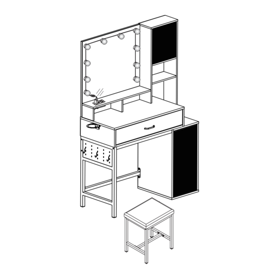
J3L420BS01
WhatsApp community↑
As this item contains many parts, please read the installation
instruction carefully before installation . Please use tools
properly and carefully. If you have any questions about the
product and installation, please contact us.
service@vabchesofficial.com
Our professional after-sales team will serve you online all
day.
1-36
Advertisement

Related Manuals for VABCHES J3L420BS01


Summary of Contents for VABCHES J3L420BS01
- Page 1 J3L420BS01 WhatsApp community↑ As this item contains many parts, please read the installation instruction carefully before installation . Please use tools properly and carefully. If you have any questions about the product and installation, please contact us. service@vabchesofficial.com Our professional after-sales team will serve you online all day.
-
Page 2: Before You Start
Before You Start Read through each step carefully and follow the proper order Separate and count all your parts and hardware Give yourself enough room for the assembly process Have the following tools: Flat Head Screwdriver, #2 Phillips Head Screwdriver and Hammer Cau�on: If using a power drill or power screwdriver for screwing, please be aware of to slow down and stop when screw is �ght. - Page 3 Board Iden�fica�on Not actual size Qty:1 Qty:1 Qty:1 Qty:1 Qty:1 Qty:2 Qty:1 Qty:1 Qty:2 Qty:1 3-36...
- Page 4 Board Iden�fica�on Not actual size Qty:1 Qty:1 Qty:1 Qty:1 Qty:1 Qty:1 Qty:1 Qty:1 Qty:1 4-36...
- Page 5 Board Iden�fica�on Not actual size Qty:1 Qty:1 Qty:1 Qty:1 Qty:1 Qty:1 Qty:1 Qty:1 Qty:1 5-36...
- Page 6 Board Iden�fica�on Qty:1 Qty:1 Qty:1 Qty:2 Qty:2 Qty:1 Qty:1 Qty:1 Qty:1 6-36...
- Page 7 Board Iden�fica�on Not actual size 7-36...
-
Page 8: Part List
Part List Ø15X9.5mm Ø6.5X35mm Ø8X30mm Ø6X30mm CAM LOCK CAM BOLT WOODEN DOWEL WOODEN DOWEL spare:3 spare:3 spare:3 spare:2 M6X40mm Ø6.3X50mm M6X12mm M6X35mm SCREW SCREW SCREW SCREW spare:2 spare:1 spare:1 spare:1 Ø4X40mm Ø3.5X14mm Ø4X14mm Ø3X14mm SCREW SCREW SCREW SCREW spare:2 spare:2 spare:1 spare:3 Ø3.5X12mm... - Page 9 Part List 350mm 350mm 19DL 19DR LEFT DRAWER RUNNER RIGHT DRAWER RUNNER Ø3X12mm X1 set TIPPING RESTRAINT PLUG BOARD SCREW HARDWARE KIT spare:1 X8 set SCREW spare:1 Cam Lock Fastening System Insert the cam bolt into the hole first, then insert the cam lock and lock it. The opening must point toward the edge of the board 9-36...
- Page 10 STEP1 Ø15X9.5mm Ø6.5X35mm Ø4X40mm Proper orientation of CAM LOCK 10-36...
- Page 11 STEP2 Ø3.5X14mm 350mm 350mm 19DL 19DR 11-36...
- Page 12 STEP3 Ø3.5X12mm Ø6.5X35mm Ø15X9.5mm Ø6X30mm Proper orientation of CAM LOCK 12-36...
- Page 13 STEP4 Ø6X30mm Ø15X9.5mm Ø6.5X35mm Proper orientation of CAM LOCK 13-36...
- Page 14 STEP5 Ø4X40mm Ø6.5X35mm Ø6X30mm 14-36...
- Page 15 STEP6 Ø8X30mm Ø15X9.5mm Ø4X40mm Ø6X30mm 15-36...
- Page 16 STEP7 Ø4X40mm Ø8X30mm Ø6X30mm Ø6.3X50mm 16-36...
- Page 17 STEP8 Ø3.5X14mm 350mm 350mm Ø6.5X35mm 19CL 19CR 19CL 19CR 17-36...
- Page 18 STEP9 Ø8X30mm Ø15X9.5mm Proper orientation of CAM LOCK 18-36...
- Page 19 STEP10 M6X40mm Ø6.3X50mm 4X65mm M6X12mm 19-36...
- Page 20 STEP11 Ø6.5X35mm 20-36...
- Page 21 STEP12 Ø8X30mm Ø15X9.5mm Proper orientation of CAM LOCK 21-36...
- Page 22 STEP13 M6X40mm Ø6.3X50mm 4X65mm 22-36...
- Page 23 STEP14 Ø6X30mm Ø8X30mm Ø15X9.5mm Ø4X40mm Proper orientation of CAM LOCK 23-36...
- Page 24 STEP15 Ø8X30mm Ø15X9.5mm Proper orientation of CAM LOCK 24-36...
- Page 25 STEP16 Ø8X30mm Ø6.3X50mm 25-36...
- Page 26 STEP17 Ø15X9.5mm Proper orientation of CAM LOCK 26-36...
- Page 27 STEP18 Ø3X14mm X1 set 27-36...
- Page 28 STEP19 28-36...
- Page 29 STEP20 Ø3.5X12mm 29-36...
- Page 30 STEP21 To adjust the vertical height. Loosen the four screws "A" on both hinges. Two of them are usually in slotted holes which allows you to adjust up or down by a few mm. Then tighten back up. To adjust depth. Loosen screw "B"...
- Page 31 STEP22 M4X18mm 107X10X21mm X8 set Cabinet Slide Drawer Slide 31-36...
- Page 32 STEP23 Ø3X12mm 109X99X38.5mm Ø4X14mm 32-36...
- Page 33 STEP24 STEP 33-36...
- Page 34 STEP25 For specific installation and debugging, please read the last two pages PEFOAM ABS lamp holder USB power adapter Switch regulator 34-36...
- Page 35 STEP26 M6X12mm M6X35mm 4X65mm M6X35mm Before you install this screw, please make sure the screw size is M6*35mm M6X12mm Before you install this screw, please make sure the screw size is M6*12mm M6X35mm Please tighten the screws to 80% first, and tighten all screws 100% after all parts are assembled.
- Page 36 STEP27 NOTE :The �pping restraint hardware included is for wooden stud wall construc�on. It must be a�ached to a wall stud. Depending upon your wall construc�on different We have included a set of �pping restraint hardware for anchor hardware maybe required. Please contact your local this unit.