Advertisement
Quick Links
J3L313BS01
WhatsApp community↑
As this item contains many parts, please read the installation
instruction carefully before installation . Please use tools
properly and carefully. If you have any questions about the
product and installation, please contact us.
service@vabchesofficial.com
Our professional after-sales team will serve you online all
day.
1-30
Advertisement

Related Manuals for VABCHES J3L313BS01


Summary of Contents for VABCHES J3L313BS01
- Page 1 J3L313BS01 WhatsApp community↑ As this item contains many parts, please read the installation instruction carefully before installation . Please use tools properly and carefully. If you have any questions about the product and installation, please contact us. service@vabchesofficial.com Our professional after-sales team will serve you online all day.
-
Page 2: Before You Start
Before You Start Read through each step carefully and follow the proper order Separate and count all your parts and hardware Give yourself enough room for the assembly process Have the following tools: Flat Head Screwdriver, #2 Phillips Head Screwdriver and Hammer Caution: If using a power drill or power screwdriver for screwing, please be aware of to slow down and stop when screw is tight. -
Page 3: Board Identification
Board Identification Not actual size DRESSING MIRROR FIXED SHELF UPPER LEFT SIDE PANEL Qty:1 Qty:1 Qty:1 UPPER RIGHT SIDE PANEL UPPER PARTITION DESK TOP Qty:1 Qty:1 Qty:1 LEFT SIDE PANEL RIGHT SIDE PANEL PARTITION Qty:1 Qty:1 Qty:1 BOTTOM BACK PANEL LEFT DRAWER FRONT Qty:1 Qty:1... - Page 4 Board Identification Not actual size RIGHT DRAWER FRONT LEFT DRAWER SIDE RIGHT DRAWER SIDE Qty:1 Qty:2 Qty:2 DRAWER BACK DRAWER BOTTOM STOOL PANEL Qty:2 Qty:2 Qty:1 GLASS TABLE LEGS STOOL LEG Qty:1 Qty:4 Qty:4 RAIL DRAWER PARTITION BOARD Qty:2 Qty:5 4-30...
-
Page 5: Part List
Part List Ø15X9.5mm Ø6.5X35mm Ø8X30mm Ø4X40mm CAM LOCK CAM BOLT WOODEN DOWEL SCREW spare:2 spare:2 spare:2 spare:2 Ø6.3X50mm M6X25mm Ø3.5X14mm Ø3X12mm SCREW SCREW SCREW SCREW spare:1 spare:1 spare:2 spare:1 Ø4X14mm Ø3X14mm Ø109X99X38.5mm SCREW SCREW PLUG BOARD HAIR DRYER RACK spare:3 spare:2 14"... - Page 6 Part List 4X65mm HEX KEY Cam Lock Fastening System Insert the cam bolt into the hole first, then insert the cam lock and lock it. The opening must point toward the edge of the board 6-30...
- Page 7 Board Identification Not actual size 7-30...
- Page 8 STEP1 Ø4X40mm 8-30...
- Page 9 STEP2 Ø15X9.5mm Ø6.5X35mm Insert the cam bolt into the hole first, then insert the cam lock and lock it. Proper orientation of CAM LOCK 9-30...
- Page 10 STEP3 14" 14" 350mm 350mm Ø3.5X14mm 13DL 13DR 13DR 13DL & 10-30...
- Page 11 STEP4 14" 14" 350mm 350mm Ø3.5X14mm 13CL 13CR 13CL 13CL 13CR 13CR 11-30...
- Page 12 STEP5 14" 14" 350mm 350mm Ø3.5X14mm 13CL 13CR 13CR 13CR FLIP OVER 13CL 13CL 12-30...
- Page 13 STEP6 Ø8X30mm 13-30...
- Page 14 STEP7 Ø15X9.5mm Ø6.5X35mm Ø8X30mm Insert the cam bolt into the hole first, then insert the cam lock and lock it. with hole Proper orientation of CAM LOCK 14-30...
- Page 15 STEP8 Ø4X40mm Place an item at one end of the desktop to make the desktop stable, which will make the next installations more convenient. Supporting objects 15-30...
- Page 16 STEP9 Ø6.5X35mm 16-30...
- Page 17 STEP10 Ø15X9.5mm Insert the cam bolt into the hole first, then insert the cam lock and lock it. Proper orientation of CAM LOCK 17-30...
- Page 18 STEP11 Ø4X40mm 18-30...
- Page 19 STEP12 Ø4X14mm bottom view When installing the feet, please refer to the bottom view to know the direction of the assembled feet. 19-30...
- Page 20 STEP13 Ø4X14mm bottom view When installing the feet, please refer to the bottom view to know the direction of the assembled feet. 20-30...
- Page 21 STEP14 Ø3X12mm Ø4X14mm Ø109X99X38.5mm You can install the hair dryer rack(12) on the left or right according to your needs 21-30...
- Page 22 STEP15 Ø3X14mm Before attaching the back panel, be sure that the unit is at 90°. 22-30...
- Page 23 STEP16 Ø6.3X50mm 4X65mm 23-30...
- Page 24 STEP17 M6X25mm 4X65mm X1 set THIS STEP REQUIRES 2 PEOPLE Please tighten the screws to 80% first, and tighten all screws 100% after all parts are assembled. 24-30...
- Page 25 STEP18 Light strip switch Lamp remote control X1 set butt joint 25-30...
- Page 26 STEP19 26-30...
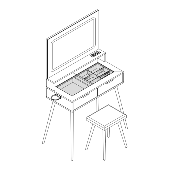
- Page 27 STEP20 Can freely cut your own size, DIY combination to create the desired style, and classify storage for a new experience . Cabinet Slide Drawer Slide 27-30...
- Page 28 STEP21 Ø21mm Stick the exposed holes of the cabinet body with hole stickers (14) 28-30...
- Page 29 STEP22 To use the remote control function of the light strip, please read the light strip manual. 29-30...
- Page 30 STEP23 We have included a set of tipping restraint hardware for NOTE :The tipping restraint hardware included is for this unit. You must install this hardware to prevent accidents or injuries that can result from the unit falling. wooden stud wall construction. It must be attached to a wall stud.