Advertisement
Quick Links
WhatsApp community↑
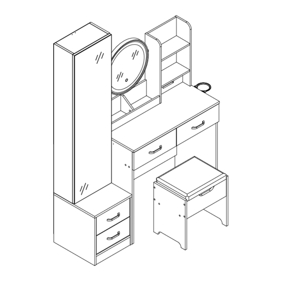
J3L116BS01
There are two installation options, you can choose.
1
2
As this item contains many parts, please read the installation
instruction carefully before installation . Please use tools
properly and carefully. If you have any questions about the
product and installation, please contact us.
service@vabchesofficial.com
Our professional after-sales team will serve you online all
day.
1-54
Advertisement

Related Manuals for VABCHES J3L116BS01


Summary of Contents for VABCHES J3L116BS01
- Page 1 WhatsApp community↑ J3L116BS01 There are two installation options, you can choose. As this item contains many parts, please read the installation instruction carefully before installation . Please use tools properly and carefully. If you have any questions about the product and installation, please contact us.
-
Page 2: Before You Start
Before You Start Read through each step carefully and follow the proper order Separate and count all your parts and hardware Give yourself enough room for the assembly process Have the following tools: Flat Head Screwdriver, #2 Phillips Head Screwdriver and Hammer Caution: If using a power drill or power screwdriver for screwing, please be aware of to slow down and stop when screw is tight. -
Page 3: Board Identification
Board Identification Not actual size LEFT SIDE PANEL RIGHT SIDE PANEL Qty:1 Qty:1 Qty:1 PARTITION FRONT SLAT BACK SLAT Qty:1 Qty:1 Qty:1 REAR LOWER PANEL UPPER LEFT PANEL UPPER RIGHT PANEL Qty:1 Qty:1 Qty:1 3-54... -
Page 4: Front Panel
Board Identification Not actual size FRONT PANEL FIXED SHELF FIXED SHELF Qty:1 Qty:1 Qty:1 LEFT PARTITION RIGHT PARTITION REAR BAFFLE Qty:1 Qty:1 Qty:1 COSMETIC MIRROR SUPPORT PLATE FRONT BAFFLE Qty:1 Qty:1 Qty:1 4-54... -
Page 5: Drawer Bottom
Board Identification Not actual size LEFT DRAWER FRONT UPPER RIGHT BACK PANEL MIRROR SUPPORT TUBE Qty:1 Qty:1 Qty:1 RIGHT DRAWER FRONT DRAWER LEFT SIDE DRAWER RIGHT SIDE Qty:4 Qty:4 Qty:1 DRAWER BACK PANEL DRAWER BOTTOM CABINET TOP Qty:2 Qty:1 Qty:2 5-54... - Page 6 Board Identification Not actual size CABINET LEFT SIDE PANEL CABINET RIGHT SIDE PANEL DOOR Qty:1 Qty:1 Qty:1 STOOL SIDE PANEL STOOL FRONT APRON STOOL BACK APRON Qty:1 Qty:1 Qty:2 SPONGE CUSHION BACK SLAT STOOL BOTTOM BOARD Qty:1 Qty:1 Qty:1 6-54...
- Page 7 Board Identification Not actual size FRONT SLAT CABINET LEFT SIDE PANEL FRONT PANEL Qty:1 Qty:1 Qty:1 CABINET RIGHT SIDE PANEL FIXED SHELF FIXED SHELF Qty:1 Qty:2 Qty:1 SMALL DRAWER FRONT UPPER BACK PANEL LOWER BACK PANEL Qty:1 Qty:1 Qty:1 7-54...
- Page 8 Board Identification Not actual size SMALL DRAWER BOTTOM SMALL DRAWER BACK PANEL Qty:2 Qty:2 8-54...
-
Page 9: Part List
Part List Ø15X9.5mm Ø6X35mm Ø6X30mm Ø8X30mm CAM LOCK CAM BOLT WOOD DOWEL WOOD DOWEL spare:3 spare:3 spare:3 spare:3 Ø6.3X50mm M6*28mm Ø4X35mm Ø3X12mm SCREW SCREW SCREW SCREW spare:3 spare:1 spare:3 spare:1 Ø3.5X14mm Ø3X14mm M4X19mm 107*10*20mm SCREW SCREW SCREW HANDLE spare:3 spare:3 spare:1 14"... - Page 10 Part List Ø15XH18mm Ø35mm Ø25mm 109*99*38.5mm PLASTIC SHEATH HINGE HINGE HAIR DRYER RACK spare:1 Ø4X14mm X2set SCREW HOOKING THE POWER PLUG SCREW spare:1 spare:1 spare:3 Cam Lock Fastening System Insert the cam bolt into the hole first, then insert the cam lock and lock it.
- Page 11 Board Identification Not actual size 11-54...
- Page 12 STEP1 Ø15X9.5mm Ø6X35mm Ø6X30mm Ø4X35mm Ø21mm Insert the cam bolt into the hole first, then insert the cam lock and lock it. Proper orientation of CAM LOCK EDGE BANDING 12-54...
- Page 13 STEP2 Ø6X35mm Ø6X30mm Ø4X35mm 13-54...
- Page 14 STEP3 M6*28mm Ø15XH18mm Ø21mm Before you install this screw, please make sure the screw size is M6*28mm Before you install this screw, please make sure the screw size is M6*28mm 14-54...
- Page 15 STEP4 Ø6X35mm Ø6X30mm X1set 15-54...
- Page 16 STEP5 Ø15X9.5mm WITHOUT EDGE BANDING EDGE BANDING Insert the cam bolt into the hole first, then insert the cam lock and lock it. Proper orientation of CAM LOCK 16-54...
- Page 17 STEP6 Ø15X9.5mm Insert the cam bolt into the hole first, then insert the cam lock and lock it. Proper orientation of CAM LOCK 17-54...
- Page 18 STEP7 Ø6X35mm 18-54...
- Page 19 STEP8 Ø6X30mm Ø21mm 19-54...
- Page 20 STEP9 M6*28mm Ø4X35mm 20-54...
- Page 21 STEP10 14" 14" Ø3.5X14mm 350mm 350mm 16CL 16CR 16CL 16CR 21-54...
- Page 22 STEP11 14" 14" Ø3.5X14mm 350mm 350mm 16CL 16CR Flip 16CL 16CR 22-54...
- Page 23 STEP12 Ø6X30mm Ø4X35mm 23-54...
- Page 24 STEP13 Ø6X30mm 24-54...
- Page 25 STEP14 Ø6.3X50mm 4X65mm 25-54...
- Page 26 STEP15 Ø6.3X50mm 4X65mm 26-54...
- Page 27 STEP16 Ø6X30mm Ø21mm 27-54...
- Page 28 STEP17 Ø15X9.5mm Ø21mm THIS STEP REQUIRES 2 PEOPLE Insert the cam bolt into the hole first, then insert the cam lock and lock it. Proper orientation of CAM LOCK 28-54...
- Page 29 STEP18 Ø15X9.5mm M6*28mm 62*15*22mm Ø21mm THIS STEP REQUIRES 2 PEOPLE NOTES:The metal ring covers the plastic sheath NOTES:The metal ring covers the plastic sheath , The opening of the plastic Opening forward sheath faces forward. Before you install this screw, please make sure the screw size is M6*28mm Insert the cam bolt into...
- Page 30 STEP19 Ø15X9.5mm Ø6X35mm Ø4X35mm & Step 1 & Step 3 Step 2 Insert the cam bolt into the hole first, then insert the cam lock and lock it. Proper orientation of CAM LOCK 30-54...
- Page 31 STEP20 14" 14" Ø3.5X14mm 350mm 350mm 16DL 16DR 16DL 16DR & 31-54...
- Page 32 STEP21 M4X19mm 107*10*20mm Ø3X12mm Cabinet Slide Drawer Slide 32-54...
- Page 33 STEP22 Ø8X30mm Ø6X35mm THE RIGHT DIRECTION FINISH No. 23 hardware completion direction Ø8X30mm 33-54...
- Page 34 STEP23 Ø8X30mm X1set Ø8X30mm 34-54...
- Page 35 STEP24 Ø15X9.5mm 90° Insert the cam bolt into the hole first, then insert the cam lock and lock it. Proper orientation of CAM LOCK 35-54...
- Page 36 STEP25 4X65mm Ø6.3X50mm Ø6X35mm 90° 36-54...
- Page 37 STEP26 14" 14" Ø3.5X14mm 350mm 350mm 16CL 16CR 16CL 16CR 37-54...
- Page 38 STEP27 Ø8X30mm Ø6X35mm 38-54...
- Page 39 STEP28 Ø8X30mm Ø15X9.5mm Ø6X35mm Insert the cam bolt into the hole first, then insert the cam lock and lock it. Proper orientation of CAM LOCK 39-54...
- Page 40 STEP29 Ø15X9.5mm HOLES Insert the cam bolt into the hole first, then insert the cam lock and lock it. Proper orientation of CAM LOCK 40-54...
- Page 41 STEP30 Ø15X9.5mm Insert the cam bolt into the hole first, then insert the cam lock and lock it. Proper orientation of CAM LOCK 41-54...
- Page 42 STEP31 Ø15X9.5mm Insert the cam bolt into the hole first, then insert the cam lock and lock it. Proper orientation of CAM LOCK 42-54...
- Page 43 STEP32 Ø3X14mm 90° 90° Before attaching the back panel, be sure that the unit is at 90°. 43-54...
- Page 44 STEP33 Ø15X9.5mm Ø6X35mm Ø4X35mm Step 1 Step 3 Step 2 Insert the cam bolt into the hole first, then insert the cam lock and lock it. Proper orientation of CAM LOCK 44-54...
- Page 45 STEP34 14" 14" Ø3.5X14mm 350mm 350mm 16DL 16DR 16DL 16DR 45-54...
- Page 46 STEP35 M4X19mm 107*10*20mm Cabinet Slide Drawer Slide 46-54...
- Page 47 STEP36 Ø3.5X14mm Ø35mm 47-54...
- Page 48 STEP37 THIS STEP REQUIRES 2 PEOPLE Ø3.5X14mm Pre-drilled Locked with panel Pre-drilled. After you adjustable the gap, You can Locked the other three screws. The DD plate is lifted up as much as possible, and the No. 19 hardware hole position and the MM plate hole position are aligned, otherwise the DD plate will sink.
- Page 49 STEP38 To adjust the vertical height. Loosen the four screws "A" on both hinges. Two of them are usually in slotted holes which allows you to adjust up or down by a few mm. Then tighten back up. To adjust depth. Loosen screw "B"...
- Page 50 STEP39 4X65mm Ø8X30mm Ø6.3X50mm Note: the hole faces inward 50-54...
- Page 51 STEP40 Ø3.5X14mm Ø21mm Ø25mm 51-54...
- Page 52 STEP41 Ø4X14mm 109*99*38.5mm There are two installation options, you can choose,figure 1 and figure 2. Figure 1 Figure 2 52-54...
-
Page 53: Touch Switch
STEP42 When making upcan use the switch to turn on or off the light. the dressing table brings you 3temperature light modes, touch the button you can easy light up the mirror and changeet your different needs, long press to adjust the brightness TOUCH SWITCH 53-54... - Page 54 STEP43 NOTE :The tipping restraint hardware included is for wooden stud wall construction. It must be attached to a wall stud. Depending upon your wall construction different anchor hardware maybe required. Please contact your local hardware store for assistance. Young children can be X2set seriously injured by tipping furniture.