Advertisement
Quick Links
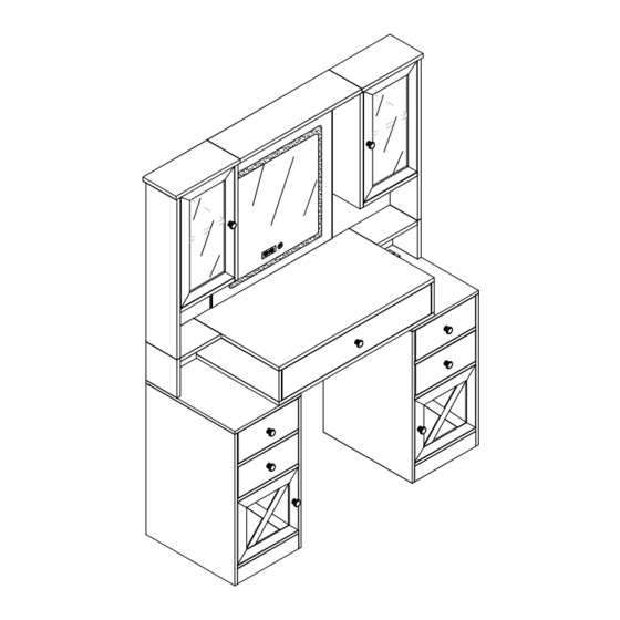
JY9980BR01 /JY9980BS01
As this item contains many parts, please read the installation
instruction carefully before installation . Please use tools
properly and carefully. If you have any questions about the
product and installation, please contact us.
service@vabchesofficial.com
Our professional after-sales team will serve you online all
day.
1-44
Advertisement

Related Manuals for VABCHES JY9980BR01


Summary of Contents for VABCHES JY9980BR01
- Page 1 JY9980BR01 /JY9980BS01 As this item contains many parts, please read the installation instruction carefully before installation . Please use tools properly and carefully. If you have any questions about the product and installation, please contact us. service@vabchesofficial.com Our professional after-sales team will serve you online all day.
- Page 2 Before You Start Read through each step carefully and follow the proper order Separate and count all your parts and hardware Give yourself enough room for the assembly process Have the following tools: Flat Head Screwdriver, #2 Phillips Head Screwdriver and Hammer Caution: If using a power drill or power screwdriver for screwing, please be aware of to slow down and stop when screw is tight.
- Page 3 Board ldentification Not actual size 1 x1 3 x1 2 x1 Middle rigth panel Middle upper panel Middle left panel 4 x1 5 x1 6 x1 Middle back panel Lower left side panel Middle lower panel 7 x1 8 x1 9 x1 Lower rigth side panel Left lower left small panel...
- Page 4 Board ldentification Not actual size Lower rigth panel Upper left roof panel Upper rigth roof panel Mirror panel Upper top plate Left upper door panel Lower rigth panel Rigth upper door panel Lower left panel Lower rigth panel Lower left panel Left back panel Support strip Lower left support strip...
- Page 5 Board ldentification Not actual size Lower right door panel Lower left door panel Drawer panel Drawer left panel Drawer right panel Drawer Backboard Drawer support strip Drawer bottom plate Drawer panel Drawer bottom plate Drawer Backboard 5-44...
- Page 6 Board ldentification 6-44...
- Page 7 Part List Ø6x35mm Ø6x30mm Ø4x35mm Ø3x12mm Ø15x10mm D x39 (+3) E x80(+4) x71(+4) x79(+4) x80(+4) Flat Head Screw Cam Bolt Dowel Cam Lock Tapping Screw Ø6x18mm Ø8x15mm Ø3.5x12mm Ø4x16mm Counter lock male Handle and Handle Counter lock nut screw Screw Power supply socket screw and Flat gasket screw...
- Page 8 Part List Cam Lock Fastening System Insert the cam bolt into the hole first, then insert the cam lock and lock it. The opening must point toward the edge of the board 8-44...
- Page 9 STEP 1 L300mm L300mm Ø3x12mm CL x4 9-44...
- Page 10 STEP 2 Ø6x35mm Ø3.5x14mm 10-44...
- Page 11 STEP 3 Ø15x10mm Ø6x30mm Proper orientation of CAM LOCK 36 32 11-44...
- Page 12 STEP 4 Ø15x10mm Ø6x30mm Proper orientation of CAM LOCK 12-44...
- Page 13 STEP 5 13-44...
- Page 14 STEP 6 Ø6x35mm 14-44...
- Page 15 STEP 7 Ø15x10mm Ø6x30mm Proper orientation of CAM LOCK 15-44...
- Page 16 STEP 8 Ø3.5x12mm 16-44...
- Page 17 STEP 9 L300mm L300mm Ø3x12mm CL x1 Ø4x35mm Ø6x30mm 17-44...
- Page 18 STEP 10 Ø6x18mm Ø8x15mm 18-44...
- Page 19 STEP 11 Ø6x35mm Ø15x10mm Ø6x30mm Proper orientation of CAM LOCK 19-44...
- Page 20 STEP 12 Ø6x35mm Ø6x30mm 20-44...
- Page 21 STEP 13 Ø6x35mm Ø6x30mm 21-44...
- Page 22 STEP 14 Ø15x10mm Ø6x30mm Need Two or More People To Complete Proper orientation of CAM LOCK 22-44...
- Page 23 STEP 15 Ø6x35mm Ø15x10mm Ø6x30mm Ø6x55mm Proper orientation of CAM LOCK 23-44...
- Page 24 STEP 16 Ø15x10mm Ø6x30mm Ø4x35mm Proper orientation of CAM LOCK 24-44...
- Page 25 STEP 17 Ø6x35mm Ø15x10mm Ø6x30mm Ø6x55mm Proper orientation of CAM LOCK 25-44...
- Page 26 STEP 18 Ø15x10mm Ø6x30mm Ø4x35mm Proper orientation of CAM LOCK 26-44...
- Page 27 STEP 19 Ø15x10mm Ø6x30mm Ø4x35mm 27-44...
- Page 28 STEP 20 Ø6x35mm Ø15x10mm Ø6x30mm Ø3.5x14mm Ø6x55mm Proper orientation of CAM LOCK 28-44...
- Page 29 STEP 21 Ø15x10mm Ø6x30mm Ø4x35mm Proper orientation of CAM LOCK 29-44...
- Page 30 STEP 22 Ø3x12mm 30-44...
- Page 31 STEP 23 31-44...
- Page 32 STEP 24 Ø3x12mm 32-44...
- Page 33 STEP 25 Ø3x16mm Ø4x14mm 33-44...
- Page 34 STEP 26 34-44...
- Page 35 STEP 27 Ø3x12mm 35-44...
- Page 36 STEP 28 36-44...
- Page 37 STEP 29 Ø6x35mm Ø4x35mm 37-44...
- Page 38 STEP 30 Ø15x10mm L300mm L300mm Ø3x12mm 43 44 Proper orientation of CAM LOCK 38-44...
- Page 39 STEP 31 Ø6x35mm Ø4x35mm 39-44...
- Page 40 STEP 32 Ø15x10mm L300mm L300mm Ø3x12mm Proper orientation of CAM LOCK 40-44...
- Page 41 STEP 33 41-44...
- Page 42 STEP 34 Power Supply 42-44...
- Page 43 STEP 35 Instructions for using Smart Mirror Lamp touch switch HOME button 1. Three-color controllable lighting Touch the HOME button to control the light switch and light color adjustment. When the light is on, long press the HOME button to control the light brightness (the light brightness can be remembered).
- Page 44 STEP 36 Ø4x35mm Ø6x30mm WALL WALL drilling hole Ø6x30mm WALL mirror Please tear off the film on the outside of the mirror. Power Supply 44-44...