Table of Contents
Advertisement
Quick Links
Using the TPS43061 Boost Evaluation Module (EVM)
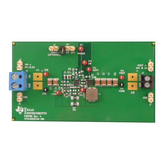
This user's guide contains information for the TPS43061EVM-198 evaluation module (PWR198) including
the performance specifications, schematic, and the bill of materials.
1
2
3
4
1
2
3
4
5
6
7
8
9
10
11
12
13
14
SLVU799A - November 2012 - Revised March 2013
Submit Documentation Feedback
Figure 1. TPS43061EVM-198 EVM Board
..................................................................................................................
....................................................................................................
..........................................................................................
...............................................................................................................
......................................................................................
35
...........................................................................................
........................................................................................
..........................................................................................
.................................................................................................
.............................................................................................................
..............................................................................................
..............................................................................................
.................................................................................
.................................................................................................
.................................................................................................
....................................................................................................
IN
....................................................................................................
.................................................................................................
IN
Copyright © 2012-2013, Texas Instruments Incorporated
SLVU799A - November 2012 - Revised March 2013
35
Contents
List of Figures
Using the TPS43061 Boost Evaluation Module (EVM)
User's Guide
3
5
11
13
1
6
7
7
7
7
8
8
8
9
9
9
9
10
1
Advertisement
Table of Contents

Related Manuals for Texas Instruments TPS43061


Summary of Contents for Texas Instruments TPS43061
-
Page 1: Table Of Contents
User's Guide SLVU799A – November 2012 – Revised March 2013 Using the TPS43061 Boost Evaluation Module (EVM) Figure 1. TPS43061EVM-198 EVM Board This user's guide contains information for the TPS43061EVM-198 evaluation module (PWR198) including the performance specifications, schematic, and the bill of materials. - Page 2 ............TPS43061EVM-198 Performance Specification Summary ..................EVM Connectors and Test points ..................TPS43061EVM-198 Bill of Materials Using the TPS43061 Boost Evaluation Module (EVM) SLVU799A – November 2012 – Revised March 2013 Submit Documentation Feedback Copyright © 2012–2013, Texas Instruments Incorporated...
-
Page 3: Introduction
Background The TPS43061 is a DC-DC synchronous boost controller designed for a maximum output voltage of 60 V from an input voltage source of 4.5 V to 38 V. It has a 5.5-V gate-drive supply optimized for use with low Qg NexFETs. - Page 4 UVLO start threshold UVLO stop threshold Modifications These EVMs are designed to provide access to the features of the TPS43061. Some modifications can be made to this module. For further details please see the product data sheet. 1.3.1 Output Voltage Set Point To change the output voltage of the EVM, it is necessary to change the value of resistor R8.
-
Page 5: Test Setup And Results
3-pin header for EN jumper. Install jumper from pins 1-2 to enable or pins 2-3 to disable. SLVU799A – November 2012 – Revised March 2013 Using the TPS43061 Boost Evaluation Module (EVM) Submit Documentation Feedback Copyright © 2012–2013, Texas Instruments Incorporated... -
Page 6: Efficiency Versus Load Current
Vin = 9V Vin = 12V Output Current - A C001 Figure 2. Efficiency Versus Load Current Using the TPS43061 Boost Evaluation Module (EVM) SLVU799A – November 2012 – Revised March 2013 Submit Documentation Feedback Copyright © 2012–2013, Texas Instruments Incorporated... -
Page 7: Regulation Versus Output Current
Frequency - Hz C004 Time = 200 µs/div Figure 5. Load Transient Response Figure 6. Loop Response SLVU799A – November 2012 – Revised March 2013 Using the TPS43061 Boost Evaluation Module (EVM) Submit Documentation Feedback Copyright © 2012–2013, Texas Instruments Incorporated... -
Page 8: Output Voltage Ripple Ccm
C4: I C1: SW Time = 500 µs/div Figure 9. Output Voltage Ripple Pulse Skip Mode Using the TPS43061 Boost Evaluation Module (EVM) SLVU799A – November 2012 – Revised March 2013 Submit Documentation Feedback Copyright © 2012–2013, Texas Instruments Incorporated... -
Page 9: Input Voltage Ripple Ccm
Time = 5.00 ms/div Figure 12. Start Up Relative to V Figure 13. Start Up Relative to EN SLVU799A – November 2012 – Revised March 2013 Using the TPS43061 Boost Evaluation Module (EVM) Submit Documentation Feedback Copyright © 2012–2013, Texas Instruments Incorporated... -
Page 10: Shutdown Relative To
EN resistor divider, the TPS43061 shuts down, PGOOD is pulled low and the output falls to ground. The output has a 2-A resistive load. -
Page 11: Schematic And Bill Of Materials
150pF 11.0k 0.015uF C12 100pF 0.1uF ISNS- ISNS+ Not Populated VBIAS (OPTIONAL) Figure 17. TPS43061EVM-198 Schematic SLVU799A – November 2012 – Revised March 2013 Using the TPS43061 Boost Evaluation Module (EVM) Submit Documentation Feedback Copyright © 2012–2013, Texas Instruments Incorporated... - Page 12 3. These assemblies must comply with workmanship standards IPC-A-610 Class 2. 4. Ref designators marked with an asterisk ('**') cannot be substituted. All other components can be substituted with equivalent MFG's components. Using the TPS43061 Boost Evaluation Module (EVM) SLVU799A – November 2012 – Revised March 2013 Submit Documentation Feedback...
-
Page 13: Board Layout
, and SW. Also on the top layer are all other components to allow the user to easily view, probe, and evaluate the TPS43061 control IC. The remaining area is filled with ground. The remaining three layers have additional copper for VIN, VOUT, AGND, and PGND connected with multiple vias. -
Page 14: Tps43061Evm-198 Top-Side Layout
Board Layout www.ti.com Figure 19. TPS43061EVM-198 Top-Side Layout Figure 20. TPS43061EVM-198 Layer 2 Layout Using the TPS43061 Boost Evaluation Module (EVM) SLVU799A – November 2012 – Revised March 2013 Submit Documentation Feedback Copyright © 2012–2013, Texas Instruments Incorporated... -
Page 15: Tps43061Evm-198 Layer 3 Layout
0603 components for easy modifications and places all components on one layer so this area may be reduced. SLVU799A – November 2012 – Revised March 2013 Using the TPS43061 Boost Evaluation Module (EVM) Submit Documentation Feedback Copyright © 2012–2013, Texas Instruments Incorporated... - Page 16 Any exceptions to this are strictly prohibited and unauthorized by Texas Instruments unless user has obtained appropriate experimental/development licenses from local regulatory authorities, which is responsibility of user including its acceptable authorization.
- Page 17 FCC Interference Statement for Class B EVM devices This equipment has been tested and found to comply with the limits for a Class B digital device, pursuant to part 15 of the FCC Rules. These limits are designed to provide reasonable protection against harmful interference in a residential installation. This equipment generates, uses and can radiate radio frequency energy and, if not installed and used in accordance with the instructions, may cause harmful interference to radio communications.
- Page 18 Also, please do not transfer this product, unless you give the same notice above to the transferee. Please note that if you could not follow the instructions above, you will be subject to penalties of Radio Law of Japan. Texas Instruments Japan Limited (address) 24-1, Nishi-Shinjuku 6 chome, Shinjuku-ku, Tokyo, Japan http://www.tij.co.jp...
- Page 19 FDA Class III or similar classification, then you must specifically notify TI of such intent and enter into a separate Assurance and Indemnity Agreement. Mailing Address: Texas Instruments, Post Office Box 655303, Dallas, Texas 75265 Copyright © 2012, Texas Instruments Incorporated...
- Page 20 IMPORTANT NOTICE Texas Instruments Incorporated and its subsidiaries (TI) reserve the right to make corrections, enhancements, improvements and other changes to its semiconductor products and services per JESD46, latest issue, and to discontinue any product or service per JESD48, latest issue.
Need help?
Do you have a question about the TPS43061 and is the answer not in the manual?
Questions and answers