Table of Contents
Advertisement
Quick Links
www.ti.com
User's Guide
TPS40195 Buck Controller Evaluation Module User's
Guide
1
Introduction.............................................................................................................................................................................2
2 Description..............................................................................................................................................................................
2.1
Applications........................................................................................................................................................................2
2.2 Features.............................................................................................................................................................................
4
Schematic................................................................................................................................................................................4
Points..........................................................................................................................................................................5
Setup................................................................................................................................................................................5
5.1 Equipment..........................................................................................................................................................................
Setup................................................................................................................................................................7
6 Test Procedure........................................................................................................................................................................
6.1 Line and Load Regulation..................................................................................................................................................
6.5 Switch Node (TP4) and SYNC (TP12).............................................................................................................................
6.6 Equipment Shutdown.......................................................................................................................................................
Regulation.................................................................................................................................................11
7.2 Efficiency..........................................................................................................................................................................
7.3 Output Voltage Ripple......................................................................................................................................................
7.4 Transient Response.........................................................................................................................................................
Plots........................................................................................................................................................................13
7.6 Test Point Waveforms......................................................................................................................................................
Materials.....................................................................................................................................................................17
10 Revision History.................................................................................................................................................................
Trademarks
All trademarks are the property of their respective owners.
SLUU297B - DECEMBER 2007 - REVISED JANUARY 2022
Submit Document Feedback
Table of Contents
Specifications........................................................................................................3
TP13)..........................................................................................................................8
TP10)........................................................................................................................................9
(TP9)............................................................................................................................10
Layout.................................................................................................................................15
Copyright © 2022 Texas Instruments Incorporated
Curves.............................................................................11
TPS40195 Buck Controller Evaluation Module User's Guide
Table of Contents
2
2
5
8
8
10
10
11
12
12
14
17
1
Advertisement
Table of Contents

Subscribe to Our Youtube Channel
Related Manuals for Texas Instruments TPS40195


Summary of Contents for Texas Instruments TPS40195
-
Page 1: Table Of Contents
9 List of Materials..................................17 10 Revision History................................. Trademarks All trademarks are the property of their respective owners. SLUU297B – DECEMBER 2007 – REVISED JANUARY 2022 TPS40195 Buck Controller Evaluation Module User's Guide Submit Document Feedback Copyright © 2022 Texas Instruments Incorporated... -
Page 2: Introduction
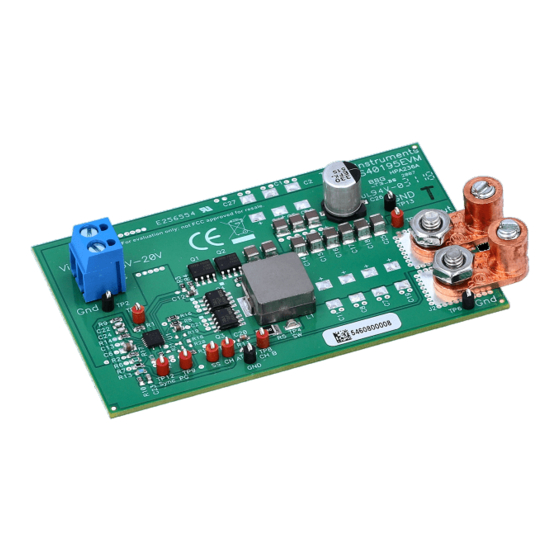
The TPS40195EVM is designed to use a regulated 12-V bus (8 V to 20 V) to produce a regulated 3.3-V output at up to 20 A of load current. TPS40195EVM is designed to demonstrate the TPS40195 in a typical 12-V bus to low-voltage application while providing a number of test points to evaluate the performance of the TPS40195 in a given application. -
Page 3: Tps40195Evm Electrical Performance Specifications
= 8 to 20 V, I = 0 to 20 A, with Operating temperature range — — °C SLUU297B – DECEMBER 2007 – REVISED JANUARY 2022 TPS40195 Buck Controller Evaluation Module User's Guide Submit Document Feedback Copyright © 2022 Texas Instruments Incorporated... -
Page 4: Schematic
Figure 4-1. TPS40195EVM Schematic for Reference Only, See Table 9-1 List of Materials for Specific Values TPS40195 Buck Controller Evaluation Module User's Guide SLUU297B – DECEMBER 2007 – REVISED JANUARY 2022 Submit Document Feedback Copyright © 2022 Texas Instruments Incorporated... -
Page 5: Test Points
Power Good Monitor power good signal at this point, see Section 6.4. TP10 General ground connection TP11 DISABLE Short TP11 to TP2 to disable the TPS40195 controller, see Section 6.4. TP12 SYNC Inject square wave synchronizing pulse here, see Section 6.5. - Page 6 The EVM should not be left unattended while powered. The EVM should not be probed while the fan is not running. TPS40195 Buck Controller Evaluation Module User's Guide SLUU297B – DECEMBER 2007 – REVISED JANUARY 2022 Submit Document Feedback Copyright ©...
-
Page 7: Equipment Setup
3.3V measurement 0 to 20A 0 to 20V Figure 5-1. TPS40195EVM Recommended Test Setup SLUU297B – DECEMBER 2007 – REVISED JANUARY 2022 TPS40195 Buck Controller Evaluation Module User's Guide Submit Document Feedback Copyright © 2022 Texas Instruments Incorporated... -
Page 8: Test Procedure
Probe Tip TP13 Figure 6-1. Output Ripple Measurement - Tip and Barrel Using TP5 and TP13 TPS40195 Buck Controller Evaluation Module User's Guide SLUU297B – DECEMBER 2007 – REVISED JANUARY 2022 Submit Document Feedback Copyright © 2022 Texas Instruments Incorporated... -
Page 9: Loop Analysis (Tp7, Tp8, Tp10)
LOAD1 3.3V 0 to 20A 0 to 20V Network Analyzer Figure 6-2. Control Loop Measurement Setup SLUU297B – DECEMBER 2007 – REVISED JANUARY 2022 TPS40195 Buck Controller Evaluation Module User's Guide Submit Document Feedback Copyright © 2022 Texas Instruments Incorporated... -
Page 10: Disable (Tp11) And Power Good (Tp9)
2.5V < V < 6.0V < 0.5V T < 1/(1.2 x F Time Figure 6-3. Typical TPS40195EVM SYNC Signal. The TPS40195 Synchronizes on the Falling Edge. 6.6 Equipment Shutdown 1. Shut down the oscilloscope. 2. Shut down LOAD1. 3. Shut down V 4. -
Page 11: Tps40195Evm Typical Performance Data And Characteristic Curves
= 8 V to 20 V, V = 3.3 V, I = 1 A to 20 A SLUU297B – DECEMBER 2007 – REVISED JANUARY 2022 TPS40195 Buck Controller Evaluation Module User's Guide Submit Document Feedback Copyright © 2022 Texas Instruments Incorporated... -
Page 12: Output Voltage Ripple
, Ch2: V = 12 V, I = 4 A to 20 A, Ch1: I , Ch2: V TPS40195 Buck Controller Evaluation Module User's Guide SLUU297B – DECEMBER 2007 – REVISED JANUARY 2022 Submit Document Feedback Copyright © 2022 Texas Instruments Incorporated... -
Page 13: Bode Plots
= 20 A, Crossover Frequency = 48 kHz, Phase = 0 A, Crossover Frequency = 46 kHz, Phase Margin = 57.5° Margin = 62° SLUU297B – DECEMBER 2007 – REVISED JANUARY 2022 TPS40195 Buck Controller Evaluation Module User's Guide Submit Document Feedback Copyright © 2022 Texas Instruments Incorporated... -
Page 14: Test Point Waveforms
Figure 7-10. TPS40195EVM Switching Waveform (Ch1: TP4) and Synchronization (Ch2: TP12) V = 12 V, = 10 A, f = 400 kHz SYNC TPS40195 Buck Controller Evaluation Module User's Guide SLUU297B – DECEMBER 2007 – REVISED JANUARY 2022 Submit Document Feedback Copyright © 2022 Texas Instruments Incorporated... -
Page 15: Evm Assembly Drawings And Layout
Figure 8-1. TPS40195EVM Component Placement (Viewed from Top) Figure 8-2. TPS40195EVM Top Copper (Viewed from Top) SLUU297B – DECEMBER 2007 – REVISED JANUARY 2022 TPS40195 Buck Controller Evaluation Module User's Guide Submit Document Feedback Copyright © 2022 Texas Instruments Incorporated... - Page 16 EVM Assembly Drawings and Layout www.ti.com Figure 8-3. TPS40195EVM Bottom Copper (X-ray Viewed from Top) TPS40195 Buck Controller Evaluation Module User's Guide SLUU297B – DECEMBER 2007 – REVISED JANUARY 2022 Submit Document Feedback Copyright © 2022 Texas Instruments Incorporated...
-
Page 17: List Of Materials
Resistor, chip, 1.0 Ω, 1210, 5% Resistor, chip, 42.2 kΩ, 1/16 W, 1% Resistor, chip, 82.5 kΩ, 1/16 W, 1% Resistor, chip, 49.9 kΩ, 1/16 W, 1% TPS40195, 4.5-V to 20-V Sync buck controller with sync TPS40195RGY and pgood 10 Revision History NOTE: Page numbers for previous revisions may differ from page numbers in the current version. - Page 18 STANDARD TERMS FOR EVALUATION MODULES Delivery: TI delivers TI evaluation boards, kits, or modules, including any accompanying demonstration software, components, and/or documentation which may be provided together or separately (collectively, an “EVM” or “EVMs”) to the User (“User”) in accordance with the terms set forth herein.
- Page 19 www.ti.com Regulatory Notices: 3.1 United States 3.1.1 Notice applicable to EVMs not FCC-Approved: FCC NOTICE: This kit is designed to allow product developers to evaluate electronic components, circuitry, or software associated with the kit to determine whether to incorporate such items in a finished product and software developers to write software applications for use with the end product.
- Page 20 www.ti.com Concernant les EVMs avec antennes détachables Conformément à la réglementation d'Industrie Canada, le présent émetteur radio peut fonctionner avec une antenne d'un type et d'un gain maximal (ou inférieur) approuvé pour l'émetteur par Industrie Canada. Dans le but de réduire les risques de brouillage radioélectrique à...
- Page 21 www.ti.com EVM Use Restrictions and Warnings: 4.1 EVMS ARE NOT FOR USE IN FUNCTIONAL SAFETY AND/OR SAFETY CRITICAL EVALUATIONS, INCLUDING BUT NOT LIMITED TO EVALUATIONS OF LIFE SUPPORT APPLICATIONS. 4.2 User must read and apply the user guide and other available documentation provided by TI regarding the EVM prior to handling or using the EVM, including without limitation any warning or restriction notices.
- Page 22 Notwithstanding the foregoing, any judgment may be enforced in any United States or foreign court, and TI may seek injunctive relief in any United States or foreign court. Mailing Address: Texas Instruments, Post Office Box 655303, Dallas, Texas 75265 Copyright © 2019, Texas Instruments Incorporated...
- Page 23 TI products. TI’s provision of these resources does not expand or otherwise alter TI’s applicable warranties or warranty disclaimers for TI products. TI objects to and rejects any additional or different terms you may have proposed. IMPORTANT NOTICE Mailing Address: Texas Instruments, Post Office Box 655303, Dallas, Texas 75265 Copyright © 2022, Texas Instruments Incorporated...
Need help?
Do you have a question about the TPS40195 and is the answer not in the manual?
Questions and answers