Advertisement
Quick Links
www.ti.com
EVM User's Guide: TPS4810Q1EVM TPS4810-Q1
TPS4810-Q1 Evaluation Module for Smart High-Side
Driver
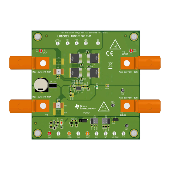
Description
The TPS4810Q1EVM allows reference circuit
evaluation of TI's TPS4810-Q1 smart high-side driver.
The TPS4810-Q1 is a 3-V to 80-V smart high-side
controller and has two strong 2-A gate drivers with
separate control inputs (INP1, INP2) to drive back
to back MOSFETs in common source configuration.
The TPS4810-Q1 provides adjustable short circuit
protection with configurable auto-retry and latch-off
fault behavior.
SLUUCV8 – OCTOBER 2023
Submit Document Feedback
Features
•
3-V to 80-V operating voltage range
•
20-A to 50-A adjustable short circuit protection
using onboard jumpers
•
Selectable high-side or low-side current sense
configuration
•
Programmable short-circuit protection delay
•
Programmable auto-retry and latch options
•
LED status indication for fault conditions
Applications
•
48-V battery management system
•
DC/DC converter
•
Automotive power distribution box
•
Cordless power tools
Copyright © 2023 Texas Instruments Incorporated
TPS4810-Q1 Evaluation Module for Smart High-Side Driver
Description
1
Advertisement

Related Manuals for Texas Instruments TPS4810-Q1


Summary of Contents for Texas Instruments TPS4810-Q1
- Page 1 3-V to 80-V operating voltage range evaluation of TI's TPS4810-Q1 smart high-side driver. • 20-A to 50-A adjustable short circuit protection The TPS4810-Q1 is a 3-V to 80-V smart high-side using onboard jumpers controller and has two strong 2-A gate drivers with •...
-
Page 2: Kit Contents
TPS1210-Q1 device can also be evaluated on this EVM by replacing the TPS48100QDGXRQ1 (U1) with TPS12100QDGXRQ1 and connecting EN/UVLO (TP3) to VAUX (TP13). This user’s guide describes the TPS4810-Q1 evaluation module (EVM). This guide provides configuration information, test setup details and contains the EVM schematics, bill of materials, assembly drawings, and top and bottom board layouts. - Page 3 Ground connection for the power supply VOUT Power output connector to the positive side of the load PGND Ground connection for the load SLUUCV8 – OCTOBER 2023 TPS4810-Q1 Evaluation Module for Smart High-Side Driver Submit Document Feedback Copyright © 2023 Texas Instruments Incorporated...
- Page 4 A DPO2024 or equivalent, three 10 times voltage probes, and a DC current probe. 2.2.2.4 Loads One resistive load or equivalent that can tolerate up to 50-A DC load at 60 V and capable of the output short. TPS4810-Q1 Evaluation Module for Smart High-Side Driver SLUUCV8 – OCTOBER 2023 Submit Document Feedback...
- Page 5 Turn OFF the power supply. • Set the jumper setting on EVM to default position as shown in Table 3-1. SLUUCV8 – OCTOBER 2023 TPS4810-Q1 Evaluation Module for Smart High-Side Driver Submit Document Feedback Copyright © 2023 Texas Instruments Incorporated...
- Page 6 Figure 3-2. Start-Up Profile of Bootstrap Voltage with INP1=INP2 = GND, CBST = 470 nF Figure 3-3. Start-Up Profile with INP1=INP2 = HIGH, CBST = 470 nF TPS4810-Q1 Evaluation Module for Smart High-Side Driver SLUUCV8 – OCTOBER 2023 Submit Document Feedback...
- Page 7 Figure 3-4. Overcurrent Response of TPS4810Q1EVM for 25-A to 35-A Load Step Figure 3-5. Auto-Retry Response of TPS48100-Q1 for an Overcurrent Fault SLUUCV8 – OCTOBER 2023 TPS4810-Q1 Evaluation Module for Smart High-Side Driver Submit Document Feedback Copyright © 2023 Texas Instruments Incorporated...
- Page 8 Implementation Results www.ti.com Figure 3-6. Latch-off Response of TPS48100-Q1 for an Overcurrent Fault Figure 3-7. Output Short-Circuit Response of TPS48100-Q1 TPS4810-Q1 Evaluation Module for Smart High-Side Driver SLUUCV8 – OCTOBER 2023 Submit Document Feedback Copyright © 2023 Texas Instruments Incorporated...
- Page 9 3. Now, toggle the SCP_TEST (TP9) and observe the response of G1PU/PD and FLTb pins during short circuit comparator (SCP) diagnosis. Figure 3-8 shows the SCP_TEST response of TPS48100-Q1 device. Figure 3-8. SCP_TEST Response of TPS48100-Q1 SLUUCV8 – OCTOBER 2023 TPS4810-Q1 Evaluation Module for Smart High-Side Driver Submit Document Feedback Copyright © 2023 Texas Instruments Incorporated...
- Page 10 Figure 3-9 shows input reverse polarity protection of TPS48100-Q1 on TPS4810Q1EVM Evaluation Board. Figure 3-9. Input Reverse Polarity Protection of TPS48100-Q1 Device TPS4810-Q1 Evaluation Module for Smart High-Side Driver SLUUCV8 – OCTOBER 2023 Submit Document Feedback Copyright © 2023 Texas Instruments Incorporated...
- Page 11 3.16k Green 68nF 680nF 100k TP19 5.6V PGND PGND PGND PGND 10ms 20A 30A Figure 4-1. TPS4810Q1EVM: Evaluation Module Schematic SLUUCV8 – OCTOBER 2023 TPS4810-Q1 Evaluation Module for Smart High-Side Driver Submit Document Feedback Copyright © 2023 Texas Instruments Incorporated...
- Page 12 Figure 4-2. TPS4810Q1EVM Board Top Overlay Figure 4-3. TPS4810Q1EVM Board Bottom Overlay Figure 4-4. TPS4810Q1EVM Board Top Layer Figure 4-5. TPS4810Q1EVM Board Bottom Layer TPS4810-Q1 Evaluation Module for Smart High-Side Driver SLUUCV8 – OCTOBER 2023 Submit Document Feedback Copyright © 2023 Texas Instruments Incorporated...
- Page 13 Hardware Design Files Figure 4-6. TPS4810Q1EVM Board Inner Signal Figure 4-7. TPS4810Q1EVM Board Inner Routing Layer Layer SLUUCV8 – OCTOBER 2023 TPS4810-Q1 Evaluation Module for Smart High-Side Driver Submit Document Feedback Copyright © 2023 Texas Instruments Incorporated...
- Page 14 Q7, Q8 MOSFET, N-CH, 60 V, 0.115 A, SOT-323 2N7002W-7-F Diodes Inc. Transistor, NPN, 160 V, 0.3 A, SOT-23 PMBT5551,215 Nexperia TPS4810-Q1 Evaluation Module for Smart High-Side Driver SLUUCV8 – OCTOBER 2023 Submit Document Feedback Copyright © 2023 Texas Instruments Incorporated...
- Page 15 TP14, TP15, TP19 TP10, TP11 Test Point, Multipurpose, Orange, TH 5013 Keystone TP16, TP17, TP18 Test Point, Multipurpose, Black, TH 5011 Keystone SLUUCV8 – OCTOBER 2023 TPS4810-Q1 Evaluation Module for Smart High-Side Driver Submit Document Feedback Copyright © 2023 Texas Instruments Incorporated...
- Page 16 RES, 3.16 k, 1%, 0.1 W, AEC-Q200 Grade 0, 0603 CRCW06033K16FKEA Vishay-Dale RZ2, RZ3, RZ5, RZ6 RES, 0, 5%, 0.063 W, AEC-Q200 Grade 0, 0402 CRCW04020000Z0ED Vishay-Dale TPS4810-Q1 Evaluation Module for Smart High-Side Driver SLUUCV8 – OCTOBER 2023 Submit Document Feedback Copyright © 2023 Texas Instruments Incorporated...
- Page 17 Additional Information 5 Additional Information Trademarks All trademarks are the property of their respective owners. SLUUCV8 – OCTOBER 2023 TPS4810-Q1 Evaluation Module for Smart High-Side Driver Submit Document Feedback Copyright © 2023 Texas Instruments Incorporated...
- Page 18 STANDARD TERMS FOR EVALUATION MODULES Delivery: TI delivers TI evaluation boards, kits, or modules, including any accompanying demonstration software, components, and/or documentation which may be provided together or separately (collectively, an “EVM” or “EVMs”) to the User (“User”) in accordance with the terms set forth herein.
- Page 19 www.ti.com Regulatory Notices: 3.1 United States 3.1.1 Notice applicable to EVMs not FCC-Approved: FCC NOTICE: This kit is designed to allow product developers to evaluate electronic components, circuitry, or software associated with the kit to determine whether to incorporate such items in a finished product and software developers to write software applications for use with the end product.
- Page 20 www.ti.com Concernant les EVMs avec antennes détachables Conformément à la réglementation d'Industrie Canada, le présent émetteur radio peut fonctionner avec une antenne d'un type et d'un gain maximal (ou inférieur) approuvé pour l'émetteur par Industrie Canada. Dans le but de réduire les risques de brouillage radioélectrique à...
- Page 21 www.ti.com EVM Use Restrictions and Warnings: 4.1 EVMS ARE NOT FOR USE IN FUNCTIONAL SAFETY AND/OR SAFETY CRITICAL EVALUATIONS, INCLUDING BUT NOT LIMITED TO EVALUATIONS OF LIFE SUPPORT APPLICATIONS. 4.2 User must read and apply the user guide and other available documentation provided by TI regarding the EVM prior to handling or using the EVM, including without limitation any warning or restriction notices.
- Page 22 Notwithstanding the foregoing, any judgment may be enforced in any United States or foreign court, and TI may seek injunctive relief in any United States or foreign court. Mailing Address: Texas Instruments, Post Office Box 655303, Dallas, Texas 75265 Copyright © 2023, Texas Instruments Incorporated...
-
Page 23: Important Notice
TI products. TI’s provision of these resources does not expand or otherwise alter TI’s applicable warranties or warranty disclaimers for TI products. TI objects to and rejects any additional or different terms you may have proposed. IMPORTANT NOTICE Mailing Address: Texas Instruments, Post Office Box 655303, Dallas, Texas 75265 Copyright © 2023, Texas Instruments Incorporated...
Need help?
Do you have a question about the TPS4810-Q1 and is the answer not in the manual?
Questions and answers