Table of Contents
Advertisement
Quick Links
www.ti.com
User's Guide
TPS40100 Buck Controller Evaluation Module User's
Guide
1
Introduction.............................................................................................................................................................................2
2 Description..............................................................................................................................................................................
2.1
Applications........................................................................................................................................................................2
2.2 Features.............................................................................................................................................................................
3 Electrical Performance Specifications.................................................................................................................................
4
Schematic................................................................................................................................................................................4
Setup................................................................................................................................................................................6
5.1 Equipment..........................................................................................................................................................................
Setup................................................................................................................................................................7
Tests.........................................................................................................................................................................8
6.1
Efficiency..........................................................................................................................................................................17
6.2 Line and Load Regulation................................................................................................................................................
Stability....................................................................................................................................................................18
Materials.....................................................................................................................................................................24
9 Revision History...................................................................................................................................................................
Trademarks
All trademarks are the property of their respective owners.
SLUU224A - MAY 2005 - REVISED MARCH 2022
Submit Document Feedback
Table of Contents
Layout.................................................................................................................................19
Copyright © 2022 Texas Instruments Incorporated
Curves...........................................................................17
TPS40100 Buck Controller Evaluation Module User's Guide
Table of Contents
2
2
3
6
17
26
1
Advertisement
Table of Contents

Related Manuals for Texas Instruments TPS40100


Summary of Contents for Texas Instruments TPS40100
-
Page 1: Table Of Contents
8 List of Materials..................................24 9 Revision History................................... Trademarks All trademarks are the property of their respective owners. SLUU224A – MAY 2005 – REVISED MARCH 2022 TPS40100 Buck Controller Evaluation Module User's Guide Submit Document Feedback Copyright © 2022 Texas Instruments Incorporated... -
Page 2: Introduction
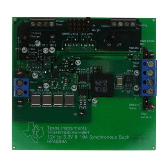
The TPS40100EVM-001 is designed to use a regulated 12-V ±10% (10.8 V–13.2 V) bus to produce a regulated 3.3-V output at up to 10 A of load current. The EVM is designed to demonstrate the TPS40100 in a typical regulated bus to low-voltage application while providing a number of test points to evaluate the performance of the TPS40100. -
Page 3: Electrical Performance Specifications
The EVM contains a power-good pin to provide the user with a “power ok” signal. This pin is pulled up through a resistor to the 5VBP pin of the TPS40100. If any of the following conditions occur, the power-good pin will pull low. -
Page 4: Schematic
Schematic www.ti.com 4 Schematic Figure 4-1. TPS40100EVM-001 Power Stage/Control Schematic TPS40100 Buck Controller Evaluation Module User's Guide SLUU224A – MAY 2005 – REVISED MARCH 2022 Submit Document Feedback Copyright © 2022 Texas Instruments Incorporated... - Page 5 Schematic Note Component values are for reference only. Figure 4-2. TPS40100EVM-001 Margin Control SLUU224A – MAY 2005 – REVISED MARCH 2022 TPS40100 Buck Controller Evaluation Module User's Guide Submit Document Feedback Copyright © 2022 Texas Instruments Incorporated...
-
Page 6: Test Setup
10-mV to 20-mV/division vertical resolution Function Generator A function generator capable of sourcing a 0-V to 5-V square wave at frequencies past 400 Khz. TPS40100 Buck Controller Evaluation Module User's Guide SLUU224A – MAY 2005 – REVISED MARCH 2022 Submit Document Feedback... -
Page 7: Equipment Setup
8. Place a fan as shown in Figure 5-2 and turn it on, making sure air is flowing across the EVM. SLUU224A – MAY 2005 – REVISED MARCH 2022 TPS40100 Buck Controller Evaluation Module User's Guide Submit Document Feedback Copyright © 2022 Texas Instruments Incorporated... -
Page 8: Other Tests
The following are the equations associated for establishing the output voltage. R1 × R3 = PARALLEL R1 + R3 TPS40100 Buck Controller Evaluation Module User's Guide SLUU224A – MAY 2005 – REVISED MARCH 2022 Submit Document Feedback Copyright © 2022 Texas Instruments Incorporated... - Page 9 If this condition occurs, check the setup and make adjustments. Please see Figure 5-3 for test setup. SLUU224A – MAY 2005 – REVISED MARCH 2022 TPS40100 Buck Controller Evaluation Module User's Guide Submit Document Feedback Copyright © 2022 Texas Instruments Incorporated...
- Page 10 7. Close the Tracking Engage (S2) (Shorting pins 2 and 3 open) and observe how VOUT tracks the TRACKING IN pins falling voltage. Waveforms should be simultaneous. TPS40100 Buck Controller Evaluation Module User's Guide SLUU224A – MAY 2005 – REVISED MARCH 2022 Submit Document Feedback Copyright ©...
- Page 11 Figure 5-5. Single EVM Tracking Charging Ramp 5.3.3.2 Single Unit Tracking (Discharge) • Channel 1 (+ 3.3 V SLUU224A – MAY 2005 – REVISED MARCH 2022 TPS40100 Buck Controller Evaluation Module User's Guide Submit Document Feedback Copyright © 2022 Texas Instruments Incorporated...
- Page 12 To demonstrate multiple EVM (2 modules) tracking, the following procedure must be followed to ensure proper functionality. The second TPS40100 EVM should be configured to a different output voltage. 1. Shunt pins 2 and 3 of the Tracking Enable Jumper (J8) for both modules.
- Page 13 17&18 Jumper TP14 Remote GND Sense Jumper Disabled Figure 5-7. TPS40100EVM-001 Dual EVM Tracking Test Setup SLUU224A – MAY 2005 – REVISED MARCH 2022 TPS40100 Buck Controller Evaluation Module User's Guide Submit Document Feedback Copyright © 2022 Texas Instruments Incorporated...
- Page 14 Closing S1 will disable the device by pulling the UVLO pin of the TPS40100 low. Opening S1 will enable the device, providing that the appropriate input voltage is present. J3 pin 4 is an enable monitor pin providing a connection for user observation.
- Page 15 0-V to 5-V square wave with a 50% duty cycle. Once power is applied to the EVM, apply the external SLUU224A – MAY 2005 – REVISED MARCH 2022 TPS40100 Buck Controller Evaluation Module User's Guide Submit Document Feedback...
- Page 16 Channel 2 external clock signal • = 12 V • = 10 A Figure 5-13. Synchronization TPS40100 Buck Controller Evaluation Module User's Guide SLUU224A – MAY 2005 – REVISED MARCH 2022 Submit Document Feedback Copyright © 2022 Texas Instruments Incorporated...
-
Page 17: Tps40100Evm Typical Performance Data And Characteristics Curves
Load Current (A) Figure 6-2. TPS40100EVM-001 Line Regulation = 10 A, V = 10.8 V–13.2 V SLUU224A – MAY 2005 – REVISED MARCH 2022 TPS40100 Buck Controller Evaluation Module User's Guide Submit Document Feedback Copyright © 2022 Texas Instruments Incorporated... -
Page 18: Loop Stability
Figure 6-3. TPS40100EVM-001 Loop Response = 12 V, V = 3.3 V, I = 10 A TPS40100 Buck Controller Evaluation Module User's Guide SLUU224A – MAY 2005 – REVISED MARCH 2022 Submit Document Feedback Copyright © 2022 Texas Instruments Incorporated... -
Page 19: Evm Assembly Drawings And Layout
4-layer, 2-oz copper-clad 3.0-inch × 3.25-inch circuit board with most of the components on the top side to allow the user to easily view, probe, and evaluate the TPS40100 control IC in a practical application. Moving components to both sides of the PCB or using additional internal layers can offer additional size reduction for space constrained systems. - Page 20 EVM Assembly Drawings and Layout www.ti.com Figure 7-2. TPS40100EVM-001 Silkscreen (Viewed from Top) TPS40100 Buck Controller Evaluation Module User's Guide SLUU224A – MAY 2005 – REVISED MARCH 2022 Submit Document Feedback Copyright © 2022 Texas Instruments Incorporated...
- Page 21 Figure 7-3. TPS40100EVM-001 Top Copper (Viewed from Top) Figure 7-4. TPS40100EVM-001 Layer 2 (X-Ray View from Top) SLUU224A – MAY 2005 – REVISED MARCH 2022 TPS40100 Buck Controller Evaluation Module User's Guide Submit Document Feedback Copyright © 2022 Texas Instruments Incorporated...
- Page 22 EVM Assembly Drawings and Layout www.ti.com Figure 7-5. TPS40100EVM-001 Layer 3 (X-Ray View from Top) TPS40100 Buck Controller Evaluation Module User's Guide SLUU224A – MAY 2005 – REVISED MARCH 2022 Submit Document Feedback Copyright © 2022 Texas Instruments Incorporated...
- Page 23 EVM Assembly Drawings and Layout Figure 7-6. TPS40100EVM-001 Bottom Copper (X-Ray View from Top) SLUU224A – MAY 2005 – REVISED MARCH 2022 TPS40100 Buck Controller Evaluation Module User's Guide Submit Document Feedback Copyright © 2022 Texas Instruments Incorporated...
-
Page 24: List Of Materials
Inductor, SMT, 1.9 μH, 20 0.512 × PG0077.202 Pulse only) A, 3.00 mΩ 0.551 inch Engineering TPS40100 Buck Controller Evaluation Module User's Guide SLUU224A – MAY 2005 – REVISED MARCH 2022 Submit Document Feedback Copyright © 2022 Texas Instruments Incorporated... - Page 25 0.28 inch × G12AP Toggle (Initial switch 0.18 inch position closed shorting pins 1 and 2) SLUU224A – MAY 2005 – REVISED MARCH 2022 TPS40100 Buck Controller Evaluation Module User's Guide Submit Document Feedback Copyright © 2022 Texas Instruments Incorporated...
-
Page 26: Revision History
Updated the numbering format for tables, figures, and cross-references throughout the document....2 • Updated the user's guide title..........................TPS40100 Buck Controller Evaluation Module User's Guide SLUU224A – MAY 2005 – REVISED MARCH 2022 Submit Document Feedback Copyright © 2022 Texas Instruments Incorporated... - Page 27 TI products. TI’s provision of these resources does not expand or otherwise alter TI’s applicable warranties or warranty disclaimers for TI products. TI objects to and rejects any additional or different terms you may have proposed. IMPORTANT NOTICE Mailing Address: Texas Instruments, Post Office Box 655303, Dallas, Texas 75265 Copyright © 2022, Texas Instruments Incorporated...
Need help?
Do you have a question about the TPS40100 and is the answer not in the manual?
Questions and answers