Table of Contents
Advertisement
Quick Links
www.ti.com
User's Guide
TPS40400 Buck Controller Evaluation Module User's
Guide
1
Introduction.............................................................................................................................................................................2
2 Description..............................................................................................................................................................................
Applications............................................................................................................................................................3
2.2 Features.............................................................................................................................................................................
3 Electrical Performance Specifications.................................................................................................................................
4
Schematic................................................................................................................................................................................5
Setup................................................................................................................................................................................6
5.1 Test and Configuration Software........................................................................................................................................
5.2 Test Equipment..................................................................................................................................................................
Setup.................................................................................................................................................8
6 EVM Configuration Using the Fusion GUI..........................................................................................................................
Procedure...................................................................................................................................................11
6.2 Fusion GUI Screenshots..................................................................................................................................................
7 Test Procedure......................................................................................................................................................................
7.1 Line/Load Regulation and Efficiency Measurement Procedure.......................................................................................
7.2 Control Loop Gain and Phase Measurement Procedure.................................................................................................
7.3 List of Test Points.............................................................................................................................................................
7.4 Equipment Shutdown.......................................................................................................................................................
8 Performance Data and Typical Characteristic Curves......................................................................................................
8.1
Efficiency..........................................................................................................................................................................16
8.2 Load Regulation...............................................................................................................................................................
1.............................................................................................................................................................17
8.4 Load Transient 2..............................................................................................................................................................
8.5 Load Transient 3..............................................................................................................................................................
8.6 Input and Output Ripple...................................................................................................................................................
8.7 Switch Node and HDRV...................................................................................................................................................
Turn On......................................................................................................................................................................
8.9 Enable ON / OFF.............................................................................................................................................................
8.11 TPS40400EVM-351 Bode Plot (20-A output).................................................................................................................
9 EVM Assembly Drawing and PCB Layout..........................................................................................................................
10 List of Materials..................................................................................................................................................................
History..................................................................................................................................................................27
SLUU535A - SEPTEMBER 2011 - REVISED JANUARY 2022
Submit Document Feedback
Table of Contents
Cable......................................................................................................................................9
Pre-bias.................................................................................................................................21
Copyright © 2022 Texas Instruments Incorporated
TPS40400 Buck Controller Evaluation Module User's Guide
Table of Contents
3
3
4
6
7
11
11
14
14
14
15
15
16
16
17
18
18
19
19
20
21
22
26
1
Advertisement
Table of Contents

Related Manuals for Texas Instruments TPS40400EVM-351


Summary of Contents for Texas Instruments TPS40400EVM-351
-
Page 1: Table Of Contents
8.8 V Turn On..................................8.9 Enable ON / OFF................................8.10 Turn ON with 92% (1.1V) Pre-bias..........................21 8.11 TPS40400EVM-351 Bode Plot (20-A output)......................... 9 EVM Assembly Drawing and PCB Layout.......................... 10 List of Materials.................................. 11 Revision History..................................27 SLUU535A – SEPTEMBER 2011 – REVISED JANUARY 2022... -
Page 2: Introduction
1 Introduction The TPS40400EVM-351 evaluation module (EVM) uses the TPS40400. The TPS40400 is a synchronous buck controller that operates from a nominal 3.0-V to 20-V supply. This controller is an analog PWM controller that allows programming and monitoring via the PMBus interface. -
Page 3: Description
Description 2 Description The TPS40400EVM-351 is designed to use a regulated 12-V bus to produce a regulated 1.2-V output at up to 20 A of load current. The TPS40400EVM-351 is designed to demonstrate the TPS40400 in a typical low-voltage application while providing a number of test points to evaluate the performance of the TPS40400. -
Page 4: Electrical Performance Specifications
Electrical Performance Specifications www.ti.com 3 Electrical Performance Specifications Table 3-1. TPS40400EVM-351 Electrical Performance Specifications PARAMETER TEST CONDITIONS UNITS Input Characteristics Voltage range Maximum input current = 8 V, I = 20 A No load input current = 14 V, I... -
Page 5: Schematic
Schematic 4 Schematic Figure 4-1. TPS40400EVM-351 Circuit Schematic SLUU535A – SEPTEMBER 2011 – REVISED JANUARY 2022 TPS40400 Buck Controller Evaluation Module User's Guide Submit Document Feedback Copyright © 2022 Texas Instruments Incorporated... -
Page 6: Test Setup
, warning and fault thresholds, and switching frequency. This software is available for download at this location: http://focus.ti.com/docs/toolsw/folders/print/ fusion_digital_power_designer.html TPS40400 Buck Controller Evaluation Module User's Guide SLUU535A – SEPTEMBER 2011 – REVISED JANUARY 2022 Submit Document Feedback Copyright © 2022 Texas Instruments Incorporated... -
Page 7: Test Equipment
To measure other waveforms, adjust the oscilloscope as needed. Metal Ground Barrel Probe Tip TP17 Figure 5-1. Tip and Barrel Measurement for V Ripple SLUU535A – SEPTEMBER 2011 – REVISED JANUARY 2022 TPS40400 Buck Controller Evaluation Module User's Guide Submit Document Feedback Copyright © 2022 Texas Instruments Incorporated... -
Page 8: Recommended Test Setup
5.3 Recommended Test Setup Figure 5-2. TPS40400EVM-351 Recommended Test Set Up Figure 5-2 is the recommended test set up to evaluate the TPS40400EVM-351. It is recommended to work at an ESD-safe workstation while testing the EVM. TPS40400 Buck Controller Evaluation Module User's Guide SLUU535A –... -
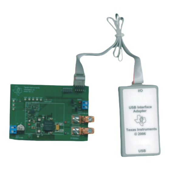
Page 9: Usb Interface Adapter And Cable
Test Setup 5.4 USB Interface Adapter and Cable Proper connection and polarity for USB interface adapter and cable. Figure 5-3. TPS40400EVM-351 USB-To-GPIO Interface Adapter 5.4.1 Input Connections 1. Prior to connecting the DC input source V , it is advisable to limit the source current from V to 10 A maximum. - Page 10 5.4.3. where regulation is desired the point of load. TPS40400 Buck Controller Evaluation Module User's Guide SLUU535A – SEPTEMBER 2011 – REVISED JANUARY 2022 Submit Document Feedback Copyright © 2022 Texas Instruments Incorporated...
-
Page 11: Evm Configuration Using The Fusion Gui
Figure 6-1. Screenshot 1: First Screen Upon Launching Fusion Software (Version may not match) Figure 6-2. Screenshot 2: Fusion Successfully Recognizes the Device on EVM SLUU535A – SEPTEMBER 2011 – REVISED JANUARY 2022 TPS40400 Buck Controller Evaluation Module User's Guide Submit Document Feedback Copyright © 2022 Texas Instruments Incorporated... - Page 12 Some parameters can be configured to values that can result in erratic or unexpected behavior on this EVM. Consult the TPS40400 datasheet for guidance in configuration of parameters. TPS40400 Buck Controller Evaluation Module User's Guide SLUU535A – SEPTEMBER 2011 – REVISED JANUARY 2022 Submit Document Feedback Copyright © 2022 Texas Instruments Incorporated...
- Page 13 EVM Configuration Using the Fusion GUI Figure 6-4. Screenshot 4: “Monitor” Screen SLUU535A – SEPTEMBER 2011 – REVISED JANUARY 2022 TPS40400 Buck Controller Evaluation Module User's Guide Submit Document Feedback Copyright © 2022 Texas Instruments Incorporated...
-
Page 14: Test Procedure
8. Decrease Load to 0 A 9. Decrease V to 0 V. 7.2 Control Loop Gain and Phase Measurement Procedure TPS40400EVM-351 contains a 49.9-Ω series resistor in the feedback loop for loop response analysis. 1. Set up EVM as described in Section 5.3 Figure 5-2. -
Page 15: List Of Test Points
Test Procedure 7.3 List of Test Points Table 7-1. TPS40400EVM-351 Test Point Functions TEST POINTS NAME DESCRIPTION Input voltage COMP Output of error amplifier Ground PGOOD Power good VOUT Output voltage SENSE + Positive remote sense HDRV High-side driver output... -
Page 16: Performance Data And Typical Characteristic Curves
Performance Data and Typical Characteristic Curves www.ti.com 8 Performance Data and Typical Characteristic Curves Figure 8-1 through Figure 8-12 represent typical performance curves for TPS40400EVM-351. 8.1 Efficiency 8−V Efficiency 12−V Efficiency 14−V Efficiency Output Current (A) G000 Figure 8-1. 8.2 Load Regulation 1.207... -
Page 17: Load Transients 1
Table 8-2. Load Transients 2 TRANSIENT TIMEBASE 5 A - 11 A 10 µs 5 A/div. Figure 8-4. SLUU535A – SEPTEMBER 2011 – REVISED JANUARY 2022 TPS40400 Buck Controller Evaluation Module User's Guide Submit Document Feedback Copyright © 2022 Texas Instruments Incorporated... -
Page 18: Load Transient
Table 8-4. Input and Output Ripple TRANSIENT TIMEBASE 14 V 20 A 400 ns Figure 8-6. TPS40400 Buck Controller Evaluation Module User's Guide SLUU535A – SEPTEMBER 2011 – REVISED JANUARY 2022 Submit Document Feedback Copyright © 2022 Texas Instruments Incorporated... -
Page 19: Switch Node And Hdrv
Turn On Table 8-6. V Turn On TRANSIENT TIMEBASE EVENT 10 A 1 ms Figure 8-8. SLUU535A – SEPTEMBER 2011 – REVISED JANUARY 2022 TPS40400 Buck Controller Evaluation Module User's Guide Submit Document Feedback Copyright © 2022 Texas Instruments Incorporated... -
Page 20: Enable On / Off
Table 8-8. Enable ON/OFF 2 TIMEBASE EVENT 10 A 20 µs CNTRL OFF CNTRL Figure 8-10. TPS40400 Buck Controller Evaluation Module User's Guide SLUU535A – SEPTEMBER 2011 – REVISED JANUARY 2022 Submit Document Feedback Copyright © 2022 Texas Instruments Incorporated... -
Page 21: Turn On With 92% (1.1V) Pre-Bias
TIMEBASE EVENT VOLTAGE PreBias Turn 14 V 1 ms CNTRL 1.1 V Vout CNTRL Figure 8-11. 8.11 TPS40400EVM-351 Bode Plot (20-A output) 8V Gain 12V Gain 14V Gain 8V Phase 12V Phase 14V Phase 1,000 10,000 100,000 Frequency (Hz) Figure 8-12. -
Page 22: Evm Assembly Drawing And Pcb Layout
The following figures (Figure 9-1 through Figure 9-4) show the design of the TPS40400EVM-351 printed circuit board. The EVM has been designed using 2 Layers, 2-oz copper circuit board. Figure 9-1. Top Assembly TPS40400 Buck Controller Evaluation Module User's Guide SLUU535A –... - Page 23 EVM Assembly Drawing and PCB Layout Figure 9-2. Top Copper SLUU535A – SEPTEMBER 2011 – REVISED JANUARY 2022 TPS40400 Buck Controller Evaluation Module User's Guide Submit Document Feedback Copyright © 2022 Texas Instruments Incorporated...
- Page 24 EVM Assembly Drawing and PCB Layout www.ti.com Figure 9-3. Bottom Copper TPS40400 Buck Controller Evaluation Module User's Guide SLUU535A – SEPTEMBER 2011 – REVISED JANUARY 2022 Submit Document Feedback Copyright © 2022 Texas Instruments Incorporated...
- Page 25 EVM Assembly Drawing and PCB Layout Figure 9-4. Top Silk SLUU535A – SEPTEMBER 2011 – REVISED JANUARY 2022 TPS40400 Buck Controller Evaluation Module User's Guide Submit Document Feedback Copyright © 2022 Texas Instruments Incorporated...
-
Page 26: List Of Materials
List of Materials www.ti.com 10 List of Materials The EVM components list according to the schematic shown in Figure 4-1. Table 10-1. TPS40400EVM-351 List of Materials REF DES DESCRIPTION PART NUMBER C1, C2, Capacitor, ceramic, 25 V, X7R, 10%, 100 nF, 0603... -
Page 27: Revision History
Revision History Table 10-1. TPS40400EVM-351 List of Materials (continued) REF DES DESCRIPTION PART NUMBER R1, R2 Resistor, chip, 1/16 W, 5%, 1 kΩ, 0603 R10, R17, Resistor, chip, 1/16 W, 1%, 10 kΩ, 0603 Resistor, chip, 1/8 W, 1%, 2.74 Ω, 1206 Resistor, chip, 1/16 W, 1%, 100 kΩ, 0603... - Page 28 STANDARD TERMS FOR EVALUATION MODULES Delivery: TI delivers TI evaluation boards, kits, or modules, including any accompanying demonstration software, components, and/or documentation which may be provided together or separately (collectively, an “EVM” or “EVMs”) to the User (“User”) in accordance with the terms set forth herein.
- Page 29 www.ti.com Regulatory Notices: 3.1 United States 3.1.1 Notice applicable to EVMs not FCC-Approved: FCC NOTICE: This kit is designed to allow product developers to evaluate electronic components, circuitry, or software associated with the kit to determine whether to incorporate such items in a finished product and software developers to write software applications for use with the end product.
- Page 30 www.ti.com Concernant les EVMs avec antennes détachables Conformément à la réglementation d'Industrie Canada, le présent émetteur radio peut fonctionner avec une antenne d'un type et d'un gain maximal (ou inférieur) approuvé pour l'émetteur par Industrie Canada. Dans le but de réduire les risques de brouillage radioélectrique à...
- Page 31 www.ti.com EVM Use Restrictions and Warnings: 4.1 EVMS ARE NOT FOR USE IN FUNCTIONAL SAFETY AND/OR SAFETY CRITICAL EVALUATIONS, INCLUDING BUT NOT LIMITED TO EVALUATIONS OF LIFE SUPPORT APPLICATIONS. 4.2 User must read and apply the user guide and other available documentation provided by TI regarding the EVM prior to handling or using the EVM, including without limitation any warning or restriction notices.
- Page 32 Notwithstanding the foregoing, any judgment may be enforced in any United States or foreign court, and TI may seek injunctive relief in any United States or foreign court. Mailing Address: Texas Instruments, Post Office Box 655303, Dallas, Texas 75265 Copyright © 2019, Texas Instruments Incorporated...
- Page 33 TI products. TI’s provision of these resources does not expand or otherwise alter TI’s applicable warranties or warranty disclaimers for TI products. TI objects to and rejects any additional or different terms you may have proposed. IMPORTANT NOTICE Mailing Address: Texas Instruments, Post Office Box 655303, Dallas, Texas 75265 Copyright © 2022, Texas Instruments Incorporated...
Need help?
Do you have a question about the TPS40400EVM-351 and is the answer not in the manual?
Questions and answers