Table of Contents
Advertisement
Quick Links
Advertisement
Table of Contents

Subscribe to Our Youtube Channel
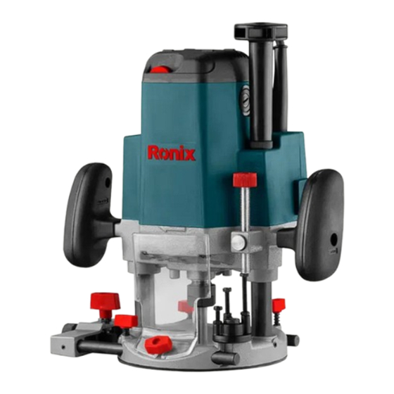
Summary of Contents for Ronix 7112V
- Page 1 ELECTRIC ROUTER 7112V...
-
Page 2: Specifications
SPECIFICATIONS Model 7112V Input Power 1850W Voltage 110V Frequency 60Hz No Load speed 5000-22000/min Collet chuck capacity 12mm Carbon brush 2pcs Guide holder 1Pc, straight guide 1pc Trimmer guide 1 pc templet guide 1pc, Accessories collet sleeve ¼, Collet sleeve 3/8’ ,Operation Manual 1pc... -
Page 3: Work Area
- Manufacturer reserves the right to change specifications without notice. - specifications may differ from country to country. GENERAL SAFETY RULES (FOR ALL TOOLS) WARNING: Read and understand all instructions. Failure to follow all instructions listed below, may result in electric shock, fire and/ or serious personal injury. -
Page 4: Personal Safety
6. Do not expose power tools to rain or wet conditions. Water entering a power tool will increase the risk of electric shock. 7. Do not abuse the cord. Never use the cord to carry the tools or pull the plug from an outlet. Keep cord away from heat, oil, sharp edges or moving parts. - Page 5 TOOL USE AND CARE 15. Use clamps or other practical way to secure and support the workpiece to a stable platform. Holding the work by hand or against your body is unstable and may lead to loss of control. 16. Do not force tool. Use the correct tool for your application. The correct tool will do the job better and safer at the rate for which it is designed.
-
Page 6: Specific Safety Rules
SPECIFIC SAFETY RULES DO NOT let comfort of familiarity with product (gained from repeated use) replace strict adherence to router safety rules. If you use this tool unsafety or incorrectly, you can suffer serious personal injury. 1. Wear hearing protection during extended period of operation. 2. - Page 7 to prevent dust inhalation and skin contact. Follow material supplier safety data. SAVE THESE INSTRUCTIONS WARNING: MISUSE or failure to follow the safety rules stated in this instruction manual may cause serious personal injury. SYMPOLS The following show the symbols used for the tool. V ----------- Voltage A ----------- ampere Hz ----------- hertz...
-
Page 8: Functional Description
FUNCTIONAL DESCRIPTION Stopper pole Fast-Feed button Adjusting Bolt ADJUSTING THE DEPTH OF CUT 1. Place the tool on a flat surface. Loosen the lock lever and lower the tool body until the bit justtouches the flat surface. Press the lock lever down to lock the tool body. - Page 9 adjustments can be obtained by turning the stopper pole (1.5 mm or about 1/16” per turn). 2. Now, your predetermined depth of cut can be obtained by loosening the lock lever and then lowering the tool body until the stopper pole makes contact with the adjusting hex bolt.
- Page 10 When the tip of the bit is retracted more than required in relate to the base plate surface, turn the knob to lower the upper limit. CAUTION: - Do not lower the knob too low. The bit will protrude dangerously STRAIGHT GUIDE The straight guide is effectively used for straight cuts when chamfering or grooving.
- Page 11 SWITCH ACTION CAUTION: - Before plugging in the tool, always check to see that the tool is switched off. - Switch can be locked in “ON” position for ease of operator comfort during extended use. Apply caution when locking tool in “ON” position and maintain firm grasp on tool.
- Page 12 guide which have a thickness of more than 15 mm (5/8”) to prevent the bit from striking the straight guide.(Fig 7) 3. When cutting, move the tool with the straight guide flush with the side of the workpiece. USER MANUAL...
- Page 13 MAINTENANCE & DAILY CHECK CAUTION: Always be sure that the tool is switch off and unplugging before attempting to perform inspection and maintenance. 1. The tool and its air vents have to be keep clean, regularly clean the tool’s air vents or whenever the vents start to become obstructed 2.
-
Page 14: Replacing Carbon Brushes
rises to the upper limit and the bit does not protrude from the tool base when the lock lever is loosened. - Before operation, always make sure that the chip deflector is installed properly. 1. Set the tool base on the workpiece to be cut without the bit making any contact. - Page 15 If the tool is not working well, ask your local Ronix service center for repair. To maintain product SAFETY and RELIABILITY, repairs, any other maintenance or adjustment should be performed by Ronix Authorized or Factory service centers, always using Ronix replacement parts. ELECTRIC ROUTER...


Need help?
Do you have a question about the 7112V and is the answer not in the manual?
Questions and answers