Table of Contents
Advertisement
Quick Links
Advertisement
Table of Contents

Related Manuals for Ronix 2603


Summary of Contents for Ronix 2603
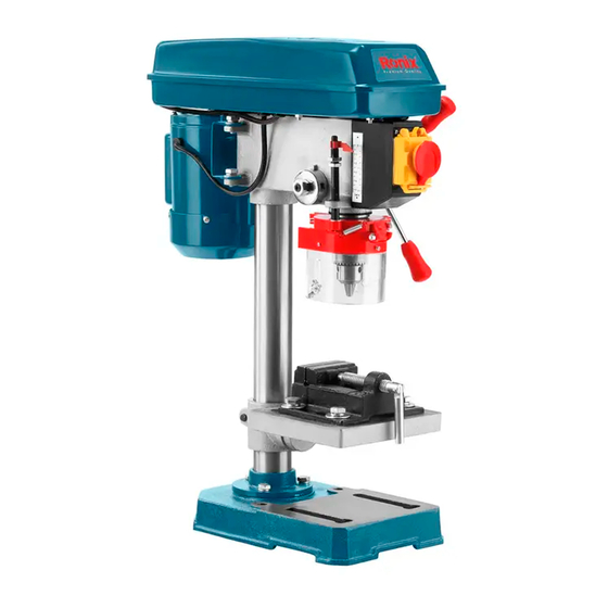
- Page 1 ELECTRIC DRILL PRESS 350W 2603...
-
Page 2: Specifications
SPECIFICATIONS Model 2603 Voltage 220-240V Power 350W Chuck Capacity 1.5-13mm Steel:13mm Drill Capacity Wood: 20mm Plastic 16mm Spindle Travel 50mm Class Of Speed Speed 620-2620RPM Spindle Taper Distance from spindle axis to the 105mm column Distance from spindle end to the... -
Page 3: Parts List
Accessories SPRING WASHER 8 OUTSIDE HEX. BOLT M8x20 HANDLE & TIP HEXAGON BAR WRENCH 3 HEXAGON BAR WRENCH 4 CROSS RECESS PAN HD SCREW M5 FLAT WASHER M5 PULLEY COVER TIP CHUCK CHUCK GUARD OUTSIDE HEX. BOLT M10x35 BENCH VICE 2.5" FLAT WASHER 10 NUT M10 PARTS LIST... - Page 4 SPECIFICATIONS WARNING! To avoid electrical hazards, fire hazards, or damage to the tool, use proper circuit protection. Use a separate electrical circuit for your tools. To avoid shock or fire, replace power cord immediately if it is worn, cut or damaged in any way. WARNING! To avoid mistakes that could cause serious injury, do not plug the Drill Press in until you have read and understood the following.
- Page 5 cause the tool to overheat. 11- WEAR PROPER APPAREL. Do not wear loose clothing, gloves, neckties, rings, bracelets, or other jewelry that may get caught in moving parts. Non-slip footwear is recommended. Wear protective hair covering to contain long hair. 12- ALWAYS WEAR EYE PROTECTION.
-
Page 6: Specific Safety Instructions
for best and safest performance. Follow instructions for lubricating and changing accessories. 22- Do not use power tools in the presence of flammable liquids or gases. SAFETY 23- DO NOT OPERATE the tool if you are under the influence of any drugs, alcohol or medication that could affect your ability to use the tool properly. - Page 7 9- DO NOT perform any operation freehand. ALWAYS hold the work piece firmly against the table so it will not rock or twist. Use clamps or a vise for unstable work pieces. 10- MAKE SURE there are no nails or foreign objects in the part of the work piece to be drilled.
- Page 8 touching the work piece. 23- TO AVOID INJURY from accidental starting, always turn the switch OFF and unplug the drill press before installing or removing any accessory or attachment or making any adjustment. NOTE: USE PROPER EXTENSION CORD. Make sure your extension cord is in good condition.
- Page 9 INSTALLING THE HEAD (FIG 4) - Carefully lift the head above the column and slide it onto the column. Make sure the head slides down over the column as far as possible. Align the head with the base. - Using the hex wrench, tighten the head lock set screws. INSTALLING FEED HANDLES (FIG 5) Locate the three feed handles in the loose parts bag.
- Page 10 INSTALL KNOB AND SCREW OF UPPER PULLEY COVER. (FIG 7) Fig 1 Fig 2 Fig 3 Fig 4 Fig 5 Fig 6 Fig 7 ADJUSTMENT TABLE ADJUSTMENT A. Tilting adjustment: Loosen lock bolt then swing table to appropriate position and retighten lock bolt.
- Page 11 SPEED ADJUSTMENT (FIG 1) - This drill press has 5 speeds shown in the speed label. To change the speed, loose the belt tension lock knob , pull the motor mounting plate to the front end then change the belt location. To tighten the belt, push the motor mounting plate to the rear end and lock the belt tension lock knob.
- Page 12 hands while drilling, you MUST position it against the LEFT side of the column. Failure to do this could result in personal injury. USING VISE (FIG 3) For small work piece that cannot be clamped to the table, use a drill press vise.
-
Page 13: Maintenance
Material SOFTWOOD HARDWOOD ACRYLIC BRASS ALUMINUM STEEL TWIST DRILL BITS 1/16-3/16`` (3-5mm) 3000 3000 2500 3000 3000 3000 1/4-3/8`` (6-10mm) 3000 1500 2000 1200 2500 1000 7/16-5/8`` (11-16mm) 1500 1500 1500 11/16-1`` (11-25mm) 1000 BRAD-POINT BITS 1/8`` 1800 1200 1500 1/4`` 1800 1000... -
Page 14: Troubleshooting Chart
Frequently blow out, using an air compressor or dust vacuum, any dust that accumulates inside the motor. A coat of paste wax applied to the table and column will help to keep the surface clean & help avoid rust. To avoid shock or fire hazard, if the power cord is worn or cut on any way, have it replaced immediately.
Need help?
Do you have a question about the 2603 and is the answer not in the manual?
Questions and answers