Table of Contents
Advertisement
KOBALT and logo design are trademarks or
registered trademarks of LF, LLC. All Rights Reserved.
ATTACH YOUR RECEIPT HERE
Serial Number
Questions, problems, missing parts? Before returning to your retailer, call our
customer service department at 888-3KOBALT (888-356-2258), 8 a.m. - 8 p.m., EST,
Monday - Sunday. You could also contact us at partsplus@lowes.com.
AS22684
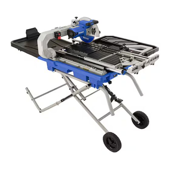
10-IN FOLDING WET TILE SAW
MFG Date
WITH STAND
Purchase Date
1
ITEM #5202571
MODEL #SC2502LW
Español p. 49
Advertisement
Table of Contents

Related Manuals for Kobalt SC2502LW


Summary of Contents for Kobalt SC2502LW
- Page 1 ITEM #5202571 10-IN FOLDING WET TILE SAW WITH STAND MODEL #SC2502LW Español p. 49 KOBALT and logo design are trademarks or registered trademarks of LF, LLC. All Rights Reserved. ATTACH YOUR RECEIPT HERE Serial Number MFG Date Purchase Date Questions, problems, missing parts? Before returning to your retailer, call our customer service department at 888-3KOBALT (888-356-2258), 8 a.m.
-
Page 2: Table Of Contents
TABLE OF CONTENTS Product Specifications......................Package Contents........................Know Your Tile Saw........................Important Safety Information..................... Electrical Safety Information..................... 11 Preparation..........................14 Assembly Instructions....................... 15 Adjustment Instructions......................32 Operating Instructions....................... 35 Care And Maintenance......................42 Troubleshooting........................45 Replacement Parts List......................Warranty............................ 48 PRODUCT SPECIFICATIONS DESCRIPTION SPECIFICATIONS... -
Page 3: Package Contents
PACKAGE CONTENTS PART DESCRIPTION QUANTITY Cutting head assembly Water tray Table frame Rear table extension Side table extension Rear water catch tray Side water catch tray Rip/Angle guide Tile clamp Cutting wheel Side splash guard Water pump... - Page 4 PART DESCRIPTION QUANTITY Center brace Inner leg assembly Left handle Right handle Upper outer tube assembly Left lower outer tube Right lower outer tube Lower brace support Stand hardware bag Wheel hardware bag Cutting head assembly locking hardware bag Wheel wrench hardware bag...
- Page 5 HARDWARE CONTENTS (not shown to actual size) PART DESCRIPTION QUANTITY M8*1.25-95 Bolt Spacer M8*1.25 T=8 Nut M6*1.0-40 Bolt Foot pad M6*1.0 T=13 Crown nut M5*0.8-40 Screw M5*0.8 T=5 Nut M8*1.25-45 Bolt φ8.2*16-0.35 Spring washer PART DESCRIPTION QUANTITY M10*1.5-95 Hex head bolt φ10*20-3 Washer M10-1.5 T=10 Lock nut Sleeve...
-
Page 6: Know Your Tile Saw
KNOW YOUR TILE SAW FRONT OF SAW PART DESCRIPTION PART DESCRIPTION Foot pads Drain plug Hitch pins Frame locking lever Tile clamp Arm folding lock knob Power cord receptacle Table inserts Filter ON/OFF switch Sliding T-fence extension Small rear flap Foot release lever Water tray lock knobs Wheels... - Page 7 PART DESCRIPTION PART DESCRIPTION Rear table extension Hold-down latch Cutting wheel Sliding table Side splash guard Side table extension lock knob Motor handle LED light ON/OFF switch Cutting depth stop knob Water nozzles Cutting head lock knob Arbor bolt Wheel wrench storage Wheel guard lock knob Wheel wrench Upper wheel guard...
-
Page 8: Important Safety Information
IMPORTANT SAFETY INFORMATION WARNING To reduce risk of injury: ● Before any use, be sure everyone using this tool reads and understands all safety instructions and other information contained in this manual. ● Save these instructions and review frequently prior to use and in instructing others. ●... - Page 9 SAFETY INSTRUCTIONS FOR TILE SAWS CAUTION ● Wear appropriate hearing protection during use. Under some conditions and duration of use, noise from this product may contribute to hearing loss. ● Do not connect unit to electrical power source until complete instructions are read and understood. ●...
- Page 10 PROPOSITION 65 WARNING WARNING: Some dust created by power sanding, sawing, grinding, drilling, and other construction activities contains chemicals known to the State of California to cause cancer, birth defects or other reproductive harm. Some examples of these chemicals are: ●...
-
Page 11: Electrical Safety Information
ELECTRICAL SAFETY INFORMATION POWER SUPPLY AND MOTOR SPECIFICATIONS WARNING: To avoid electrical hazards, fire hazards, or damage to the tool, use proper circuit protection. Use a separate electrical circuit for your tool. Your tile saw is wired at the factory for 120 V operation. - Page 12 MINIMUM GAUGE FOR EXTENSION CORDS (AWG) (When using 120 volts only) Ampere Rating Total length of Cord More Than Not More Than 25 ft. 50 ft. 100 ft. 150 ft. Not Recommended WARNING: Do not expose to rain or use in damp locations. This tool is intended for use on a circuit that has a receptacle like the one illustrated in Fig.
- Page 13 POSITION OF TILE SAW Fig. D To avoid the possibility of the appliance plug or receptacle getting wet, position the tile saw to one side of a wall-mounted receptacle to prevent water from dripping onto the receptacle or plug. The user should arrange a “drip loop” in the cord Drip connecting the saw to a receptacle (see Fig.
-
Page 14: Preparation
PREPARATION Before beginning assembly or operation of the product, make sure all parts are present. Compare parts with package contents list and hardware contents list on pages 3 to 5. If any part is missing or damaged, do not attempt to assemble, install or operate the product. Estimated Assembly Time: 60 minutes. -
Page 15: Assembly Instructions
ASSEMBLY INSTRUCTIONS WARNING: To avoid injury, do not connect this tile saw to a power source until it is completely assembled and you have read and understood the instruction manual. UNPACKING YOUR TILE SAW Carefully unpack the tile saw and all its parts, and compare against the list and illustration on pages 3 to 5. - Page 16 Assembling the left and right outer tubes (Fig. 2) - BAG U ● Attach the left lower outer tube (R) to one side of the upper outer tube assembly (Q) using two screws (gg) and two lock nuts (hh), as shown. ●...
- Page 17 Assembling the left and right outer tubes to the inner leg assembly (Fig. 4) - BAG U ● Pull the rubber strip (1) off the locking hook (2). This will expose the center hole on the outer tube. ● Position the inner leg assembly (N) and left outer tube (3) so that they resemble an “X”.
- Page 18 Assembling the lower brace support (Fig. 6) - BAG U ● Attach the lower brace support (T) to the left and right outer tubes using two hex bolts (ii), as shown. ● Tighten the hex bolts (ii) with the adjustable wrench (not included).
- Page 19 INSTALLING THE CUTTING HEAD ASSEMBLY Bottom view TO TABLE FRAME (FIG. 8) - BAG W NOTE: The cutting head assembly and table frame are heavy and it is recommended to be transported with the help of 2 people, to safely move it. ●...
- Page 20 INSTALLING THE CUTTING HEAD ASSEMBLY AND TABLE FRAME TO WATER TRAY (FIG. 9) - BAG X ● Carefully lift the cutting head assembly and table frame over the water tray (B), as shown. NOTE: The cutting head assembly and table frame are heavy and it is recommended to be transported with the help of 2 people, to safely move it.
- Page 21 INSTALLING/REMOVING THE REAR TABLE EXTENSION (FIG. 11) - BAG X Move the sliding table to its most forward position and lock in place. To install the rear table extension: ● Insert the tab (1) on the front of the rear table extension (D) under the sliding table and insert the slot (2) on the front of the rear table extension (D) into the tab on the...
- Page 22 RAISING AND LOWERING THE CUTTING HEAD ASSEMBLY (FIG. 12, 13) Raising the cutting head assembly (Fig. 12) ● Pull out the hold-down latch (SS). ● Grasp the motor handle (KK) to raise up the cutting head to a vertical position, and then release the hold-down latch (SS).
- Page 23 Lowering the cutting head assembly (Fig. 13) ● Remove the rear table extension (D). ● Loosen the arm folding lock knob (FF) and pull it out. ● Grasp the motor handle (KK) to lower the cutting head assembly backward. ● Release the arm folding lock knob (FF) and it will lock into the hole automatically to lock the arm.
- Page 24 INSTALLING THE SIDE SPLASH GUARD (FIG. 14) ● Place the side splash guard (K) over the rear guard. ● Insert the two holes on the outside of the side splash guard over the two screws (1) located on the side of the upper wheel guard (ZZ). NOTE: It is not necessary to loosen or remove the screws (1) on the wheel guard to install the side splash guard.
- Page 25 INSTALLING THE CUTTING WHEEL (FIG.15, 16, 17) WARNING ● DO NOT use cutting wheels rated less than the no load speed of this tool. Failure to heed this warning could result in personal injury. DO NOT use a wheel with cracks, gaps, or teeth.
- Page 26 ● Place arbor nut (XX) on arbor. Press and hold the arbor lock button (Aa-Fig. 16) in. Using the wheel wrench (OO) turning clockwise to tighten arbor nut (XX) securely. Release the arbor lock button. (Fig. 15) ● Close the upper wheel guard (ZZ) and tighten the wheel guard lock knob (YY). REMOVING THE CUTTING WHEEL (FIG.
- Page 27 INSTALLING AND REMOVING THE REAR WATER CATCH TRAY (FIG. 19) Installing the rear water catch tray ● Align four slots located on the rear left and right ends of the water pan with the arms of the rear water catch tray (F). ●...
- Page 28 CLOSING/EXTENDING THE STAND (FIG. 22, 23, 24, 25, 26) ● Remove water catch trays and any workpieces from the tool. ● Lower the wheel and secure by locking the cutting head in place using the cutting head lock knob (MM) and hold-down latch (SS). (Fig.
- Page 29 To extend the stand (Fig. 25, 26): ● Step on the release lever (1) and pull the left and right handles (O & P) toward you simultaneously. (Fig. 25) ● Once the stand is released from the foot release lever (BB), ease the stand toward the floor by pushing the handles toward the floor.
- Page 30 SIDE WATER CATCH TRAY STORAGE (FIG. 27) When the stand is folded, the side water catch tray (G) can be stored between the water tray and center brace. NOTE: The bottom of the side water catch tray should be placed against the stop tab (1). REAR WATER CATCH TRAY STORAGE (FIG.
- Page 31 INSTALLING THE RIP/ANGLE GUIDE (FIG. 29) The Rip/Angle guide can be used from either the left or right side of the tile saw wheel. ● Place the slot underside of the Rip/Angle guide (H) on sliding T-fence extension (AA). Lock the Rip/Angle guide (H) securely to table by turning the lock knob (1) clockwise.
-
Page 32: Adjustment Instructions
ADJUSTMENT INSTRUCTIONS WARNING: This saw was adjusted for accuracy at the factory. During shipping the components may have been moved out of alignment. In addition, usage and time will necessitate adjustments to be made. WARNING To prevent personal injury: ● Always disconnect plug from the power source when making any adjustments. - Page 33 Adjusting the cutting wheel 90° to sliding table (Fig. 32, 33) ● Disconnect the saw from the power source. ● Loosen the bevel lock knob (PP) and make sure the cutting wheel is in the maximum vertical position. Tighten the bevel lock knob (PP).
- Page 34 CUTTING WHEEL DEPTH ADJUSTMENT (FIG. 35) WARNING: Improperly adjusting the cutting wheel depth could cause the cutting wheel to come in contact with the sliding table resulting in damage to the unit and/or possible serious injury. The depth stop is factory set to provide maximum cutting capacity for the wheel provided with the saw.
-
Page 35: Operating Instructions
OPERATING INSTRUCTIONS BEFORE USING THE TILE SAW WARNING: To avoid mistakes that could cause serious, permanent injury, do not plug the tool in until the following steps are completed: ● Completely assemble and adjust the tile saw, following the instructions (SEE ASSEMBLY AND ADJUSTMENTS SECTIONS). - Page 36 USING THE RIP/ANGLE GUIDE (FIG. 37) This guide can be placed on either side of the cutting wheel. ● Loosen the lock knob (1) to move the guide along the front rail to the desired position and tighten the lock knob (1). ●...
- Page 37 EXTERNAL WATER CONTROLS (FIG. 39) Water nozzles are adjustable to provide maximum water for cutting and change water spray direction. ● The water volume control (Cc) allows easy adjustment of nozzles (WW) to provide water volume. To provide maximum water volume, turn the water volume control (Cc) clockwise.
- Page 38 LOCKING AND UNLOCKING THE SLIDING T-FENCE EXTENSION (FIG. 41) ● Lock the sliding table (TT). ● Loosen the two sliding T-fence extension lock knobs (Ee) to unlock the sliding T-fence extension (AA). ● To lock the sliding fence (AA), tighten two sliding T-fence lock knobs (Ee).
- Page 39 CUTTING OPERATION WARNING: Before making any adjustments or removing or installing attachments or accessories, make sure the switch is in the OFF position to avoid injury from an accidental start. Before turning the tile saw on, verify the alignment of the sliding table and the cutting wheel. Always center the cutting wheel in one of the sliding table grooves before cutting.
- Page 40 DIAGONAL CUT (FIG. 44) NOTE: Diagonal cuts are also referred to as “long point to point cuts.” ● Fill the water tray with clean water. ● Using a pencil or marker mark the area to be cut on tile. ● Align one point of the tile against the cut indicator (1) of the sliding table.
- Page 41 MITER CUT (FIG. 46) NOTE: Miter cuts are used for cutting outside and inside corners on material, decorative chair rail and base moulding with the material at any angle to the cutting wheel other than 90°. ● Fill the water tray with clean water. ●...
-
Page 42: Care And Maintenance
CARE AND MAINTENANCE WARNING: Do not service, clean or maintain the saw without first turning off the motor and unplugging the saw from the power source. Failure to do so may result in serious personal injury. REPLACING CARBON BRUSHES (FIG. 48) NOTICE: Replace both carbon brushes when either has less than 1/4 in. - Page 43 CLEANING THE PUMP (FIG. 49) For best performance, the pump may be cleaned periodically. ● Unplug pump before handling or cleaning the pump. ● Pull out to remove the front cover (1). ● Using a small brush and/or water, clean any debris or trash that is trapped on the inside of the pump.
- Page 44 FREE WARNING LABEL REPLACEMENT: If your warning labels become illegible or are missing, call 803-980-7740 for a free replacement. WARNING DO NOT replace the power cord. If you have any problem or questions concerning the power cord, call the Customer Service Department at 888-356-2258.
-
Page 45: Troubleshooting
TROUBLESHOOTING WARNING Do not service, clean or maintain the saw without first turning off the motor and unplugging the saw from the power source. Failure to do so may result in serious personal injury. PROBLEM POSSIBLE CAUSE CORRECTIVE ACTION Motor does not 1. -
Page 46: Replacement Parts List
REPLACEMENT PARTS LIST For replacement parts, call our customer service department at 888-3KOBALT (888-356-2258), 8 a.m. - 8 p.m., EST, Monday - Sunday. You could also contact us at partsplus@lowes.com. - Page 47 PART DESCRIPTION PART# Rear table extension 530N Rip/Angle guide 50L6 Tile clamp 50KG Side splash guard 507Q Water pump 528E Filter 50KW Spacers (set of 2) 2FUD Foot pad 2FUH Hitch pin 50KV Drain plug 530P Water tray lock knob 50P2 Cutting depth stop knob 50K5...
-
Page 48: Warranty
WARRANTY The manufacturer will offer replacement parts for this product which under normal usage have proven to be defective in their manufacture or workmanship for a period of THREE (3) years from the date of initial retail purchase. This warranty is valid only to the original purchaser. This warranty is not transferable and does not cover any parts that have been subjected to misuse, abuse, alteration, overload, accident or normal wear of moving parts.
Need help?
Do you have a question about the SC2502LW and is the answer not in the manual?
Questions and answers
Want to order slide bearings for sc2502lw as item # 5202571 which requires 3each