Advertisement
Table of Contents
- 1 Table of Contents
- 2 Product Specifications
- 3 Package Contents
- 4 Know Your Tile Saw
- 5 Important Safety Information
- 6 Electrical Safety Information
- 7 Preparation
- 8 Assembly Instructions
- 9 Adjustment Instructions
- 10 Operating Instructions
- 11 Care and Maintenance
- 12 Troubleshooting
- 13 Replacement Parts List
- 14 Warranty
- Download this manual
KOBALT and logo design are trademarks or
registered trademarks of LF, LLC. All rights reserved.
ATTACH YOUR RECEIPT HERE
Serial Number
Questions, problems, missing parts? Before returning to your retailer, call our
customer service department at 888-3KOBALT (888-356-2258), 8 a.m. - 8 p.m., EST,
Monday - Sunday. You could also contact us at partsplus@lowes.com.
SS22236
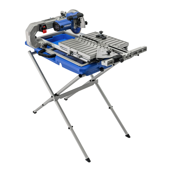
7-IN FOLDING WET TILE
MFG Date
1
SAW WITH STAND
Purchase Date
ITEM #5202572
MODEL #SC1802LW
Español p. 41
Advertisement
Table of Contents

Related Manuals for Kobalt SC1802LW


Summary of Contents for Kobalt SC1802LW
- Page 1 ITEM #5202572 7-IN FOLDING WET TILE SAW WITH STAND MODEL #SC1802LW Español p. 41 KOBALT and logo design are trademarks or registered trademarks of LF, LLC. All rights reserved. ATTACH YOUR RECEIPT HERE Serial Number MFG Date Purchase Date Questions, problems, missing parts? Before returning to your retailer, call our customer service department at 888-3KOBALT (888-356-2258), 8 a.m.
-
Page 2: Table Of Contents
TABLE OF CONTENTS Product Specifications ...................... Package Contents ......................Know Your Tile Saw......................Important Safety Information ..................... Electrical Safety Information....................Preparation........................Assembly Instructions ....................... Adjustment Instructions ..................... Operating Instructions ....................... Care And Maintenance ..................... Troubleshooting......................... Replacement Parts List ..................... Warranty ..........................PRODUCT SPECIFICATIONS DESCRIPTION SPECIFICATIONS... -
Page 3: Package Contents
PACKAGE CONTENTS PART DESCRIPTION QUANTITY Cutting head assembly Tile clamp Rip/Angle guide Water pump Cutting wheel Support legs Left support Right support Sliding table... - Page 4 PART DESCRIPTION QUANTITY Table frame Water tray Cutting wrench hardware bag Carry handle assembly hardware bag Side splash guard Stand hardware bag Cutting head assembly locking hardware bag...
- Page 5 HARDWARE CONTENTS (not shown to actual size) PART DESCRIPTION QUANTITY M6*1.0-16 Screw M6*1.0-40 Screw M6*1.0 T=5 Lock nut PART DESCRIPTION QUANTITY M8*1.25-45 Socket head bolt M8*1.25 T=8 Nut PART DESCRIPTION QUANTITY M8*1.25-40 Bolt φ8*15-1 Washer M8*1.25 T=8 Lock nut M8*1.25-70 Bolt Left anchor plate Right anchor plate PART...
-
Page 6: Know Your Tile Saw
KNOW YOUR TILE SAW FRONT OF SAW PART DESCRIPTION PART DESCRIPTION Tile Clamp Table release pin Motor handle Carry handle Arbor lock button Power cord receptacle Water volume control Arm folding lock knob Water angle control ON/OFF switch Table inserts Motor Sliding T-fence extension Cutting head lock knob... - Page 7 PART DESCRIPTION Cutting wheel Side splash guard Hold-down latch Bevel lock knob Wheel wrench storage Rear splash guard Wheel guard lock knob LED light ON/OFF switch Upper wheel guard Arbor nut Wheel wrench Water nozzles...
-
Page 8: Important Safety Information
IMPORTANT SAFETY INFORMATION WARNING To reduce risk of injury: ● Before any use, be sure everyone using this tool reads and understands all safety instructions and other information contained in this manual. ● Save these instructions and review frequently prior to use and in instructing others. ● Keep guards in place and in working order. - Page 9 SAFETY INSTRUCTIONS FOR TILE SAWS CAUTION ● Wear appropriate hearing protection during use. Under some conditions and duration of use, noise from this product may contribute to hearing loss. ● Do not connect unit to electrical power source until complete instructions are read and understood. ●...
- Page 10 PROPOSITION 65 WARNING WARNING: Some dust created by power sanding, sawing, grinding, drilling, and other construction activities contains chemicals known to the State of California to cause cancer, birth defects or other reproductive harm. Some examples of these chemicals are: ●...
-
Page 11: Electrical Safety Information
ELECTIRCAL SAFETY INFORMATION POWER SUPPLY AND MOTOR SPECIFICATIONS WARNING: To avoid electrical hazards, fire hazards, or damage to the tool, use proper circuit protection. Use a separate electrical circuit for your tool. Your tile saw is wired at the factory for 120 V operation. - Page 12 MINIMUM GAUGE FOR EXTENSION CORDS (AWG) (When using 120 volts only) Ampere Rating Total length of Cord More Than Not More Than 25 ft. 50 ft. 100 ft. 150 ft. Not Recommended WARNING: Do not expose to rain or use in damp locations. This tool is intended for use on a circuit that has a receptacle like the one illustrated in Fig.
- Page 13 POSITION OF TILE SAW Fig. D To avoid the possibility of the appliance plug or receptacle getting wet, position the tile saw to one side of a wall-mounted receptacle to prevent water from dripping onto the receptacle or plug. Power Cord The user should arrange a “drip loop”...
-
Page 14: Preparation
PREPARATION Before beginning assembly or operation of the product, make sure all parts are present. Compare parts with package contents list and hardware contents list on pages 3 to 5. If any part is missing or damaged, do not attempt to assemble, install or operate the product. Estimated Assembly Time: 30~60 minutes Tools needed to remove or install wheel (included): Wheel Wrench, 5 mm Hex Wrench. -
Page 15: Assembly Instructions
ASSEMBLY INSTRUCTIONS WARNING: To avoid injury, do not connect this tile saw to a power source until it is completely assembled and adjusted and you have read and understood the instruction manual. UNPACKING YOUR TILE SAW Carefully unpack the tile saw and all its parts, and compare against the list and illustration on pages 3 to 5. - Page 16 ASSEMBLING THE WATER TRAY ONTO THE STAND (FIG. 3) ● Place the stand on level ground. ● Line up the four grooves under the water tray (K) with the two upper support bars on the stand to put the water tray on the stand. FRONT OF SAW...
- Page 17 ASSEMBLING THE CUTTING HEAD ASSEMBLY ON THE FRAME (FIG. 4) - BAG P NOTE: The cutting head assembly and table frame are heavy and it is recommended to be transported with the help of 2 people, to safely move it. ●...
- Page 18 ASSEMBLING THE CUTTING HEAD/FRAME ON THE WATER TRAY (FIG. 5) - BAG L NOTE: The cutting head assembly and table frame are heavy and it is recommended to be transported with the help of 2 people, to safely move it. ● Place the cutting head assembly onto the water tray (K) as shown.
- Page 19 RAISING, LOWERING AND FOLDING THE CUTTING HEAD (FIG. 6, 7) NOTE: Always turn the saw OFF when raising or lowering the cutting head. To raise the cutting head (Fig. 6): ● Loosen the cutting head lock knob (DD) and then pull out the hold-down latch (FF) as shown Fig.
- Page 20 INSTALLING THE CARRY HANDLE TO FRAME (FIG. 8) - BAG M ● Align the holes in the carry handle (Y) with the holes on the table frame (J). ● Insert two socket head bolts (dd) through the carry handle and frame, secure bolts in place using hex nuts (ee).
- Page 21 To unlock the sliding table (Fig. 10) From the right side of the sliding table (I), pull the table lock lever (1) out and turn the lever as shown. To lock the sliding table (Fig. 10) ● Pull the table lock lever (1) out and slide the table, and align the lock lever with either of the two holes (2) on the table frame (J).
- Page 22 INSTALLING THE SIDE SPLASH GUARD (FIG. 12) ● Insert the two holes on the inside of the side splash guard (N) into the two screws (1) located on side of the upper wheel guard. Press into place. NOTE: It is not necessary to loosen or remove the screws (1) on the wheel guard to install the side splash guard.
- Page 23 ● Press the arbor lock button (R - Fig. 14), holding it in firmly while turning the wheel wrench counterclockwise to loosen. ● Remove the arbor nut (MM) and outer wheel flange (1). Do not remove the inner wheel flange (2). (Fig. 15) WARNING: If the inner flange (2) has been removed, replace it before placing wheel on arbor.
- Page 24 WHEEL WRENCH STORAGE (FIG. 16) For convenient storage and prevention of loss, there is a clip (HH) behind the arm (1) for storing the wheel wrench (NN) when not in use. INSTALLING THE RIP/ANGLE GUIDE (FIG. 17) The Rip/Angle guide can be used from either the left or right side of the 7 in.
- Page 25 INSTALLING THE TILE CLAMP (FIG. 18) Slot for Tile Clamp NOTE: The tile clamp is designed to be used for small or narrow pieces of tile. Use this clamp for all cuts that cannot be held firmly by the miter/ angle guide and would require your hands to be closer than 3”...
- Page 26 INSTALLING THE WATER PUMP (FIG. 19, 20) ● Move the table to the back position. ● Water pump (D) is equipped with suction feet to secure in place. Press down firmly on the water pump (D) to attach feet to bottom of the water tray (K).
-
Page 27: Adjustment Instructions
ADJUSTMENT INSTRUCTIONS WARNING: This saw was adjusted for accuracy at the factory. During shipping the components may have been moved out of alignment. In addition, usage and time will necessitate adjustments to be made. WARNING To prevent personal injury: ● Always disconnect plug from the power source when making any adjustments. - Page 28 POSITIVE STOP ADJUSTMENT (FIG. 23) NOTE: These adjustments were made at the factory and normally do not require. Adjusting the cutting wheel 90° to sliding table ● Disconnect the saw from the power source. ● Loosen the bevel lock knob (GG). Place a 90° framing square on the cutting wheel surface.
- Page 29 CUTTING WHEEL DEPTH ADJUSTMENT (FIG. 24) WARNING: Improperly adjusting the cutting wheel depth could cause the cutting wheel to come in contact with the sliding table resulting in damage to the unit and/or possible serious injury. Adjusting the cutting depth: ●...
-
Page 30: Operating Instructions
OPERATION INSTRUCTIONS BEFORE USING THE TILE SAW WARNING: To avoid mistakes that could cause serious, permanent injury, do not plug the tool in until the following steps are completed: ● Completely assemble and adjust the tile saw, following the instructions. (SEE ASSEMBLY AND ADJUSTMENTS SECTIONS). - Page 31 FILLING/CHANGING THE WATER RESERVIOR (FIG. 27) WARNING: When filling/draining water tray, make sure wet tile saw is unplugged from wall outlet. To fill the reservoir with water ● Make sure the drain plug (X) on the water tray is tight. ● Fill the water tray (K) with clean water.
- Page 32 CUTTING OPERATION WARNING: Before making any adjustments or removing or installing attachments or accessories, make sure the switch is in the OFF position to avoid injury from an accidental start. Before turning the tile cutter on, verify the alignment of the sliding table and the cutting wheel.
- Page 33 DIAGONAL CUT (FIG. 31) NOTE: Diagonal cuts are also referred to as “long point to point cuts.” ● Fill the water tray with clean water. ● Using a pencil or marker mark the area to be cut on tile. ● Align one point of the tile against the cut indicator (1) of the sliding table.
- Page 34 MITER CUT (FIG. 33) NOTE: Miter cuts are used for cutting outside and inside corners on material, decorative chair rail and base moulding with the material at any angle to the cutting wheel other than 90°. ● Using a pencil or marker mark the area to be cut on tile.
-
Page 35: Care And Maintenance
CARE AND MAINTENANCE WARNING: Do not service, clean or maintain the saw without first turning off the motor and unplugging the saw from the power source. Failure to do so may result in serious personal injury. REPLACING CARBON BRUSHES (FIG. 35) NOTICE: Replace both carbon brushes when either has less than 1/4 in. - Page 36 CLEANING THE PUMP (FIG. 36) For best performance, the pump may be cleaned periodically. ● Unplug pump before handling or cleaning the pump. ● Pull out to remove the front cover (1). ● Using a small brush and/or water, clean any debris or trash that is trapped on the inside of the pump.
-
Page 37: Troubleshooting
TROUBLESHOOTING WARNING: To avoid injury from accidental starting, always turn switch OFF and unplug the tool before moving, replacing the wheel or making adjustments. PROBLEM PROBLEM CAUSE CORRECTIVE ACTION Motor does not 1. Power cord is not plugged into the 1. -
Page 38: Replacement Parts List
REPLACEMENT PARTS LIST For replacement parts, call our customer service department at 888-3KOBALT(888-356-2258), 8 a.m. - 8 p.m., EST, Monday - Sunday. You could also contact us at partsplus@lowes.com. - Page 39 PART DESCRIPTION PART # Tile clamp 50KG Rip/Angle guide 50KF Water pump 528E Carry handle assembly hardware bag 50KH Side splash guard 505W Drain plug 530P Cutting head lock knob 52X4 Sliding T-fence lock knob 505J Bevel lock knob 53KY Rear splash guard 505V Wheel wrench...
-
Page 40: Warranty
WARRANTY The manufacturer will offer replacement parts for this product which under normal usage have proven to be defective in their manufacture or workmanship for a period of THREE (3) years from the date of initial retail purchase. This warranty is valid only to the original purchaser. This warranty is not transferable and does not cover any parts that have been subjected to misuse, abuse, alteration, overload, accident or normal wear of moving parts.
Need help?
Do you have a question about the SC1802LW and is the answer not in the manual?
Questions and answers