Table of Contents
Advertisement
Available languages
Available languages
Kobalt is a trademark of LF, LLC. All rights
reserved.
ATTACH YOUR RECEIPT HERE
Serial Number
Questions, problems, missing parts? Before returning to your retailer, call our customer
service department at 1-888-3KOBALT (1-888-356-2258), 8 a.m. - 8 p.m., EST, Monday - Friday.
PH19148
KEEP THIS MANUAL NEAR YOUR SAW FOR EASY
REFERENCE AND TO INSTRUCT OTHERS
Purchase Date
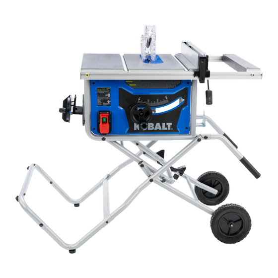
10-IN TABLE SAW
MODEL #KT10152
WARNING
To reduce risk of serious injury,
thoroughly read and comply with
all warnings and instructions in
this manual and on product.
kobalttools.com
ITEM #1303497
Français p. 51
Español p. 102
Advertisement
Chapters
Table of Contents

Related Manuals for Kobalt KT10152


Summary of Contents for Kobalt KT10152
- Page 1 KEEP THIS MANUAL NEAR YOUR SAW FOR EASY Kobalt is a trademark of LF, LLC. All rights REFERENCE AND TO INSTRUCT OTHERS reserved. ATTACH YOUR RECEIPT HERE...
-
Page 2: Table Of Contents
TABLE OF CONTENTS Package Contents ..........................3 Hardware Contents........................... 4 Safety Information ..........................5 Power Connection ...........................12 Product Specifications ........................13 Assembly Instructions........................14 Unpacking ..........................15 Table Stand Assembly .......................15 Riving Knife Installation and Positioning ..................21 Blade Installation ........................22 Anti-Kickback Pawls Installation ....................23 Blade Guard Installation ......................24 Folding Leg Stand ........................25 Before Operating ..........................26... -
Page 3: Package Contents
PACKAGE CONTENTS PART DESCRIPTION QUANTITY PART DESCRIPTION QUANTITY Blade guard Left rear leg Anti-kickback pawls Release lever Push stick Height adjusting wheel Side table extension Left leg cross piece Closed end wrench Left leg end Open end wrench Rip fence Side extension lock Miter gauge I1, I2 Right and left handles... -
Page 4: Hardware Contents
HARDWARE CONTENTS kobalttools.com... -
Page 5: Safety Information
SAFETY INFORMATION IMPORTANT SAFETY INSTRUCTIONS WARNING CAREFULLY READ AND FOLLOW ALL WARNINGS AND INSTRUCTIONS ON YOUR PRODUCT AND IN THIS MANUAL. SAVE THIS MANUAL. MAKE SURE ALL USERS ARE FAMILIAR WITH ITS WARNING AND INSTRUCTIONS WHEN USING THE TOOL. Improper operation, maintenance or modification of tools or equipment could result in serious injury and/or property damage. - Page 6 SAFETY INFORMATION DANGER Indicates an imminently hazardous situation which, if not avoided, will result in death or serious injury. WARNING Indicates a potentially hazardous situation which, if not avoided, could result in death or serious injury. CAUTION Indicates a potentially hazardous situation which, if not avoided, may result in minor or moderate injury. NOTICE Indicates a practice not related to personal injury which, if not avoided, may result in property damage.
- Page 7 SAFETY INFORMATION 3) Personal safety a) Stay alert, watch what you are doing and use common sense when operating a power tool. Do not use a power tool while you are tired or under the influence of drugs, alcohol or medication. A moment of inattention while operating power tools may result in serious personal injury.
- Page 8 SAFETY INFORMATION 1) Guarding related warnings a) Keep guards in place. Guards must be in working order and be properly mounted. A guard that is loose, damaged, or is not functioning correctly must be repaired or replaced. b) Always use saw blade guard, riving knife and anti-kickback device for every through-cutting operation.
- Page 9 SAFETY INFORMATION i) Provide auxiliary workpiece support to the rear and/or sides of the saw table for long and/or wide workpieces to keep them level. A long and/or wide workpiece has a tendency to pivot on the table’s edge, causing loss of control, saw blade binding and kickback. j) Feed workpiece at an even pace.
- Page 10 SAFETY INFORMATION k) Keep saw blades clean, sharp, and with sufficient set. Never use warped saw blades or saw blades with cracked or broken teeth. Sharp and properly set saw blades minimize binding, stalling and kickback. 4) Table saw operating procedure warnings a) Turn off the table saw and disconnect the power cord when removing the table insert, changing the saw blade or making adjustments to the riving knife, anti-kickback device or saw blade guard, and when the machine is left unattended.
- Page 11 SAFETY INFORMATION MAKING A PUSH STICK • In order to operate your table saw safely, you must use a push stick whenever the size or shape of the workpiece would otherwise cause your hands to be within 6 in. (152 mm) of the saw blade or other cutter.
-
Page 12: Power Connection
POWER CONNECTION EXTENSION CORDS WARNING • Keep the extension cord clear of the working area. Position the cord so it will not get caught on lumber, tools or other obstructions while you are working with a power tool. Failure to do so can result in serious personal injury. -
Page 13: Product Specifications
POWER CONNECTION SPEED AND WIRING • The no-load speed of this tool is approximately 5,000 RPM. This speed is not constant and decreases under a load or with lower voltage. • For voltage, the wiring in a shop is as important as the motor’s horsepower rating. A line intended only for lights cannot properly carry a power tool motor. -
Page 14: Assembly Instructions
ASSEMBLY INSTRUCTIONS WARNING • DO NOT use this product if any parts on the Loose Parts List are already assembled to your product when you unpack it. Parts on this list are not assembled to the product by the manufacturer and require customer installation. -
Page 15: Unpacking
ASSEMBLY INSTRUCTIONS UNPACKING 1. Cut sides of box at all four corners. IMPORTANT: Before assembly, separate upper and lower packing trays. Leave base section in lower tray while completing steps 1 - 8. TABLE STAND ASSEMBLY 2. First remove washers (KK) and nuts (JJ) from lower right leg assembly, then attach wheels (K) to lower right leg assembly (J) with washers (KK) (one on each side of wheel) and nut (JJ). - Page 16 ASSEMBLY INSTRUCTIONS ASSEMBLY INSTRUCTIONS 4. Attach left leg end (S) onto the leg assembly from step 3. Secure with M8 x 35mm (1.38"). cap screw (BB) and nut (EE). Note: The feet on the left leg end (S) should face to the outside (left).
- Page 17 ASSEMBLY INSTRUCTIONS 6. Attach leg assembly to table (V). Insert spacer (DD) between legs and secure with M8 x 75mm (2.95") carriage bolt (AA) and nut (EE). Note: Cut zip tie securing the pre-assembled upper leg in place. Hardware Used M8 x 75mm (2.95") Carriage bolt Spacer...
- Page 18 ASSEMBLY INSTRUCTIONS 7b. Raise the narrowest part of the stand to help align the holes. Insert spacer (DD) between legs and secure with M8 x 75mm (2.95") cap screw (AA) and nut (EE). Note: DO NOT overtighten. Cut zip tie securing pedal. Hardware Used M8 x 75mm (2.95") Carriage bolt...
- Page 19 ASSEMBLY INSTRUCTIONS 9. IMPORTANT: Release height adjustment locking lever and tilt blade to 45˚ to release and remove packing material under motor. kobalttools.com...
- Page 20 ASSEMBLY INSTRUCTIONS 10. Install height adjustment knob (FF) and M8 round head Philips screw (GG) to height adjustment wheel. Hardware Used M8 round head Philips screw Height adjustment knob kobalttools.com...
-
Page 21: Riving Knife Installation And Positioning
ASSEMBLY INSTRUCTIONS RIVING KNIFE INSTALLATION AND POSITIONING Note: This saw is shipped with riving knife in lowered position for non-through cuts. Riving knife must be placed in raised position to attach anti-kickback pawls and blade guard for all through cut operations. -
Page 22: Blade Installation
ASSEMBLY INSTRUCTIONS ASSEMBLY INSTRUCTIONS BLADE INSTALLATION CAUTION • To work properly, saw blade teeth must point down toward the front of the saw. Failure to do so could cause damage to the saw blade, the saw, or the workpiece. 1. Make sure blade is turned right way. Remove blade wrenches from storage area. -
Page 23: Anti-Kickback Pawls Installation
ASSEMBLY INSTRUCTIONS 3. To install throat plate (Y), slip tab into slot at back of saw and push down to secure in place. Note: There are four screws pre-assembled to the throat plate that can be used for leveling the throat plate if necessary. -
Page 24: Blade Guard Installation
ASSEMBLY INSTRUCTIONS BLADE GUARD INSTALLATION To install blade guard: 1. With front of blade guard (A) raised, hook back end of guard onto rear slot of riving knife (X). 2. Push front down until it is parallel to table. Lock blade guard (A) in place by pushing lever down. -
Page 25: Folding Leg Stand
FOLDING LEG STAND 1. To fold stand for moving, return side and rear extension tables to inner position. Stow rip fence and miter gauge. Grasping handles, push the stand release pedal with your foot and tilt up and forward until the saw rests on the wheels and stand feet. STORAGE FEATURES •... -
Page 26: Before Operating
BEFORE OPERATING WARNING • ALWAYS make sure your workpiece is not in contact with the blade (W) before operating the switch to start the saw. Blade contact could result in kickback or thrown workpiece. • DO NOT use blades rated less than the speed of this tool. Failure to heed this warning could result in serious personal injury. -
Page 27: Blades
BEFORE OPERATING BLADES • Your saw comes equipped with a 10 in. combination blade suitable for ripping and cross-cutting. Additional blade styles are available for specific operations such as ripping. Your local dealer can provide you with complete information. • Kerf width must be within the limits stamped on the riving knife (X). •... -
Page 28: Rip Fence
BEFORE OPERATING RIP FENCE WARNING • To reduce the risk of injury, always make sure the rip fence (T) is parallel to the blade (W) before beginning any operation. Using Rip Fence 1. Make sure both the front and rear side of fence 10 in away from the blade. -
Page 29: Miter Gauge
BEFORE OPERATING MITER GAUGE The miter gauge provides accuracy in angled cuts. For very close tolerances, test cuts are recommended. There are two miter gauge grooves, one on either side of blade, maximum 30° on both left or right side. . When making a 90° cross cut, use either miter gauge groove. When making a beveled cross cut (blade tilted in relation to table (V), miter gauge should be located in groove on right so that blade is tilted away from miter gauge and hands. -
Page 30: Slide Table Extension
BEFORE OPERATING SLIDING TABLE EXTENSION Adjust the length of the saw table (V) by using the table extension (E). Release the table by pulling side extension lock outward. 1. For rip cuts between 0 in. to 20 in., set rip fence (T) on black tabs. -
Page 31: Cutting Aids
BEFORE OPERATING CUTTING AIDS Cutting aids such as push sticks, push blocks, featherboards and jigs should be used where appropriate to maximize your ability to control your workpiece for a safe and precise cut. When making non-through cuts or ripping narrow stock, always use a push stick, push block, featherboard and/or jig set-up so hands do not come within 6 inches of saw blade (W). -
Page 32: How To Make A Push Stick
BEFORE OPERATING *Some materials mentioned in this section are sold separately. HOW TO MAKE A PUSH STICK • In order to operate your table saw safely, you must use a push stick whenever the size or shape of the workpiece would otherwise cause your hands to be within 6 in. (152 mm) of the saw blade or other cutter. -
Page 33: How To Make A Featherboard
BEFORE OPERATING HOW TO MAKE A FEATHERBOARD • Clamping a featherboard in front of the blade can increase safety during non-through cuts, like grooving and rabbeting, and through cuts. • Select a solid piece of lumber approximately 3/4 in. thick, 2-1/2 in. wide and 12 in. long. •... -
Page 34: How To Make Auxuiliary Fence
BEFORE OPERATING HOW TO MAKE AN AUXILIARY FENCE An auxiliary fence is a device used to close the gap between rip fence and saw table. ALWAYS use an auxiliary fence when ripping material 1/8 in. or thinner to prevent stock from slipping under fence. •... -
Page 35: Operating Instructions
OPERATING INSTRUCTIONS THROUGH CUTS WITH SINGLE BLADES WARNING • Always make sure the blade guard (A) and anti-kickback pawls (B) are in place and working properly when making these cuts to avoid possible injury. • DO NOT use blades rated less than the speed of this tool. Failure to heed this warning could result in personal injury. -
Page 36: Types Of Cuts
OPERATING INSTRUCTIONS Basic Types of Cuts Cross cut Cross cut Rip cut Rip cut Miter cut Miter cut Bevel cross cut Bevel cross cut Bevel rip cut Bevel rip cut Compound (bevel) Compound (bevel) miter cut miter cut Note: All other cuts are combinations of these basic six. Operating procedures for making each kind of cut are given later in this section. - Page 37 OPERATING INSTRUCTIONS 6. Turn saw on. 7. Position workpiece flat on table (V) with edge flush against rip fence (T). Let blade (W) build up to full speed before feeding workpiece into blade. 8. Once blade (W) has made contact with workpiece, use hand closest to rip fence (T) for guidance. Make sure edge of workpiece remains in solid contact with both rip fence (T) and surface of table (V).
- Page 38 OPERATING INSTRUCTIONS 8. When ripping a long workpiece, place support same height as table (V) surface behind saw for cut work. 9. Turn saw on. 10. Position workpiece flat on table (V) with edge flush against rip fence (T). Let blade build up to full speed before feeding workpiece into blade.
-
Page 39: Dados And Other Non-Through-Cuts
OPERATING INSTRUCTIONS DADOS AND OTHER NON-THROUGH CUTS The use of a non-through cut is essential to cutting grooves, rabbets and dados. Non-through cuts can be made using a standard blade having a diameter of 10 inches or less, or a dado blade up to 1/2 inches wide with a diameter of 8 inches or less. -
Page 40: Adjustments
ADJUSTMENTS WARNING Before performing any adjustment, make sure tool is unplugged from power supply and switch is in off position. Failure to do so could result in serious personal injury. The table saw has been adjusted at the factory for making very accurate cuts. However, some components might have been jarred out of alignment during shipping. -
Page 41: Replacing Blade
ADJUSTMENTS CHECKING AND ALIGNING RIVING KNIFE AND SAW BLADE See Assembly Instructions, page 21. REPLACING BLADE Note: Turn power off and unplug saw. Set bevel setting to "0". Remove blade guard (A), anti-kickback pawls (B) and throat plate (Y). Raise saw blade (W). Note: The table saw spindle shall have a normal rotation that is clockwise when viewed from the left of the position normally assumed by the operator. -
Page 42: Riving Knife And Saw Blade Alignment
ADJUSTMENTS RIVING KNIFE AND SAW BLADE ALIGNMENT Blade and riving knife alignment is set at factory and in most cases will not need to be adjusted. However, the alignment should always be checked after installing blade or riving knife, and can be adjusted if necessary. If riving knife (X) is out of alignment with blade (W), adjustment is needed. - Page 43 ADJUSTMENTS To check/adjust (vertically): 1. Place framing square on table and against both blade (W) and riving knife (X). Blade (W) and riving knife (X) are aligned if framing square contacts both blade (W) and riving knife (X) evenly with no gaps. 2.
-
Page 44: Healing (Paralleling) Blade To Miter Gauge Groove
ADJUSTMENTS HEELING (PARALLELING) BLADE TO MITER GAUGE GROOVE WARNING • Blade (W) must be parallel to miter gauge groove so that wood does not bind, resulting in kickback. Failure to do so could result in serious personal injury. • To reduce risk of injury from kickback, align rip fence (T) to blade (W) following any blade adjustments. -
Page 45: Setting Blade At 0° And 45
ADJUSTMENTS If the distances are different: 3. From underneath the table top, loosen trunnion securing bolts with a hex wrench. 4. If back of blade (W) was too close to combination square, place a block of wood on right side of blade (W) tap with a small hammer to align to square. -
Page 46: Adjusting Bevel Indicator
ADJUSTMENTS ADJUSTING BEVEL INDICATOR • Adjust bevel indicator if it is not at zero when the blade is perpendicular to the table. 1. With blade perpendicular to table, loosen screw. 2. Set indicator to 0° on bevel scale. 3. Retighten screw. CHECKING ALIGNMENT OF RIP FENCE TO MITER SLOT 1. -
Page 47: Care And Maintenance
CARE AND MAINTENANCE WARNING • When servicing, use only identical replacement parts. Use of any other parts may create a risk of personal injury or cause product damage. • Before performing any maintenance, make sure the tool is unplugged from the power supply and the switch is in the off position. -
Page 48: Troubleshooting
TROUBLESHOOTING PROBLEM POSSIBLE CAUSE CORRECTIVE ACTION Excess vibration. 1. Blade is out of balance. 1. Replace blade. 2. Blade is damaged. 2. Replace blade. 3. Legs are not properly 3. Tighten all hardware. attached to saw. 4. Work surface is uneven. 4. -
Page 49: Warranty
THREE YEAR LIMITED WARRANTY The Manufacturer will repair any product or component which under normal usage is proven to be defective in workmanship or material for a period of THREE (3) years from the date of initial retail purchase. This warranty is valid only to the original retail purchaser, as evidenced by the purchaser’s original receipt or such other proof of purchase as Manufacturer may accept. -
Page 50: Replacement Parts List
For replacement parts, call our customer service department at 1-888-3KOBALT, 8 a.m. - 8 p.m., EST, Monday - Friday. PART DESCRIPTION PART # Blade guard 201501 201503 Miter gauge 201504 Rip fence Push stick 201505 Wheel 101506 Printed in Taiwan KOBALT are registered trademarks of LF, ® LLC. All Rights Reserved. kobalttools.com... - Page 51 ARTÍCULO #1303497 SIERRA DE MESA DE 25,40 CM MODELO #KT10152 ADVERTENCIA Para reducir el riesgo de sufrir lesiones serias, lea con atención todas las advertencias e instrucciones que se encuentran en este manual y en el producto y sígalas al pie de la letra.
-
Page 52: Contenido Del Empaque
ÍNDICE Contenido del empaque ......................104 Contenido de herramientas ......................105 Información de seguridad ......................106 Conexión eléctrica .........................115 Especificaciones del producto ......................115 Instrucciones para ensamblaje .....................117 Desempaquetando ........................118 Ensamble de la base de soporte de la mesa ................118 Instalación y colocación de la cuchilla separadora ..............124 Instalación de la hoja .......................125 Instalación de trinquetes anti retroceso ...................126 Instalación del protector de la hoja ..................127... -
Page 53: Contenido De Herramientas
CONTENDIOS DEL PAQUETE Pieza Descripción Cantidad Pieza Descripción Cantidad Protector de la sierra Pata izquierda trasera Trinquetes anti retroceso Palanca de liberación Palo de empujar Rueda para ajustar la altura Extensión de la mesa Travesaño de pata Llave de boca cerrada izquierda Llave de boca abierta Extremo/izquierdo... - Page 54 CONTENDIOS DEL PAQUETE Tuerca para tornillo para Espaciador metales CANT. 6 CANT. 10 M8 x 35 mm (1.38" ) CANT. 4 M6 x 50 mm (1.97" ) CANT. 2 Tuerca para Arandela tornillo para (pre-ensamblado metales para bajar M8 x 75 mm (pre-ensamblado ensamble de pata (2.95 ") perno de...
-
Page 55: Información De Seguridad
INFORMACIÓN DE SEGURIDAD INSTRUCCIONES DE SEGURIDAD IMPORTANTES ADVERTENCIA LEA CON ATENCIÓN Y SIGA TODAS LAS ADVERTENCIAS E INSTRUCCIONES QUE SE ENCUENTRAN EN SU PRODUCTO Y EN ESTE MANUAL. CONSERVE ESTE MANUAL. ASEGÚRESE DE QUE TODOS LOS USUARIOS ESTÉN FAMILIARIZADOS CON LAS ADVERTENCIAS E INSTRUCCIONES CUANDO UTILICEN LA HERRAMIENTA. - Page 56 INFORMACIÓN DE SEGURIDAD PELIGRO Indica una situación de peligro inminente que, si no se previene, causará la muerte o una lesión seria. ADVERTENCIA Indica una posible situación de peligro que, si no se previene, puede causar la muerte o una lesión seria. PRECAUCIÓN Indica una posible situación de peligro que, si no se previene, podría causar una lesión menor o moderada.
- Page 57 INFORMACIÓN DE SEGURIDAD enchufes sin modificaciones y que encajan en los tomacorrientes reducen el riesgo de descarga eléctrica. b) Evite el contacto del cuerpo con superficies conectadas a tierra, tales como tuberías, radiadores, extractores o refrigeradores. Si ingresa agua en una herramienta eléctrica, el riesgo de descarga eléctrica aumentará. c) No exponga las herramientas eléctricas a la lluvia o a condiciones de humedad.
- Page 58 INFORMACIÓN DE SEGURIDAD eléctricas. Este tipo de medidas de seguridad preventivas reduce el riesgo de arranques accidentales de la herramienta eléctrica d) Almacene las herramientas eléctricas que no estén en uso fuera del alcance de los niños y no permita que personas que no estén familiarizadas con la herramienta o estas instrucciones la utilicen.
- Page 59 INFORMACIÓN DE SEGURIDAD a) PELIGRO: nunca coloque los dedos o las manos cerca o en línea con la hoja de sierra. Un momento de falta de atención o un resbalón podría dirigir su mano hacia la hoja de sierra y provocar lesiones personales graves b) Introduzca la pieza de trabajo en la hoja de sierra o en el cortador solo en sentido contrario a la dirección de giro.Si se introduce la pieza de trabajo en la misma dirección en la que gira la hoja de sierra por encima de la mesa, es posible que la pieza de trabajo y su mano se vean impulsadas hacia la hoja de sierra.
- Page 60 INFORMACIÓN DE SEGURIDAD Puede producirse un contacto accidental con la hoja de sierra o el contragolpe puede arrastrar los dedos hacia la hoja de sierra. c) Nunca sostenga y presione la pieza de trabajo que está cortando contra la hoja de sierra giratoria. Presionar la pieza de trabajo que se está...
- Page 61 INFORMACIÓN DE SEGURIDAD de brindar un funcionamiento seguro y un rendimiento óptimo. i) Nunca se pare sobre la sierra de mesa, no la use como banco. Si la herramienta se voltea o si la herramienta de corte se toca accidentalmente, se pueden producir lesiones graves. j) Asegúrese de que la hoja de sierra esté...
- Page 62 INFORMACIÓN DE SEGURIDAD ADVERTENCIA ADVERTENCIA DE LA PROPOSICIÓN 65: El polvo creado por lijar, serruchar, triturar, taladrar con instrumentos mecánicos y demás actividades de construcción puede contener químicos que el estado de California considera causan cáncer, defectos de nacimiento u otros daños reproductivos. Algunos ejemplos son: –...
-
Page 63: Conexión Eléctrica
CONEXIÓN ELÉCTRICA CABLES DE EXTENSIÓN ADVERTENCIA • Mantenga el cable de extensión fuera del área de trabajo. Coloque el cable de tal forma que no quede atrapado en la madera, las herramientas u otras obstrucciones mientras esté trabajando con una herramienta eléctrica. El no hacerlo puede ocasionar lesiones personales serias. •... - Page 64 CONEXIÓN ELÉCTRICA • Una caída sustancial en el voltaje ocasionará una pérdida de potencia y el motor se sobrecalentará. • Si la sierra no funciona cuando se enchufa a una toma de corriente, vuelva a verificar la fuente de alimentación. VELOCIDAD Y ALAMBRADO •...
-
Page 65: Instrucciones Para Ensamblaje
INSTRUCCIONES DE ENSAMBLAJE ADVERTENCIA • NO utilice este producto si cualquiera de las piezas de la lista de piezas sueltas ya está ensamblada a su producto cuando lo desempaque. El fabricante no ha ensamblado las piezas de esta lista al producto y el cliente debe instalarlas. -
Page 66: Desempaquetando
INSTRUCCIONES DE ENSAMBLAJE DESEMPAQUETADO 1. Corte los lados de la caja en las cuatro esquinas IMPORTANTE: Antes de ensamblar, separe las bandejas superior e inferior del empaque. Deje la sección de base en la bandeja inferior mientras termina los pasos 1 - 8. ENSAMBLAJE DE LA BASE DE SOPORTE DE LA MESA 2. - Page 67 INSTRUCCIONES DE ENSAMBLAJE 4. Sujete el extremo de la pata izquierda (S) al ensamble de las patas del paso 3. Asegure con tornillo Allen de M8 x 35mm (1.38") (BB) y tuerca para tornillos para metales (EE). Nota: Los extremos de las patas izquierdas (S) deben apuntar hacia afuera (izquierda).
- Page 68 INSTRUCCIONES DE ENSAMBLAJE 6. Sujete el ensamble de las patas a la mesa (V). Inserte el espaciador (DD) entre las patas y asegure con el tornillo de cabeza redonda de M8 x 75mm (2.95") (AA) y la tuerca para tornillos para metales (EE).
- Page 69 INSTRUCCIONES DE ENSAMBLAJE 7b. Eleve la parte más estrecha de la base de soporte para ayudarlo a alinear los orificios. Inserte el espaciador (DD) entre las patas y asegure con el tornillo de cabeza de M8 x 75mm (2.95") (AA) y la tuerca para tornillos para metales (EE).
- Page 70 INSTRUCCIONES DE ENSAMBLAJE 9. IMPORTANTE: Libere la palanca de fijación para ajustar la altura e incline la hoja a 45˚ para liberar y retire el material del empaque debajo del motor. kobalttools.com...
- Page 71 INSTRUCCIONES DE ENSAMBLAJE 10. Instale la perilla para ajustar la altura (FF) y el Tornillo Phillips de cabeza redonda M8 (GG) a la rueda para ajustar la altura. Herramientas utilizadas Tornillo Phillips de cabeza redonda M8 Perilla para ajustar la altura kobalttools.com...
-
Page 72: Instalación Y Colocación De La Cuchilla Separadora
INSTRUCCIONES DE ENSAMBLAJE INSTALACIÓN Y COLOCACIÓN DE LA CUCHILLA SEPARADORA Nota: Esta sierra se envía con la cuchilla separadora en la posición baja para los cortes no pasantes. La cuchilla separadora debe colocarse en la posición levantada para sujetar los trinquetes anti retroceso y el protector de la hoja para todos los cortes pasantes. -
Page 73: Instalación De La Hoja
INSTRUCCIONES DE ENSAMBLAJE INSTALACIÓN DE LA HOJA PRECAUCIÓN • Para trabajar en forma correcta, los dientes de la hoja de la sierra deben apuntar hacia abajo y hacia la parte delantera de la sierra. Si no hace esto, podría dañarse la hoja de la sierra, la sierra o la pieza de trabajo. -
Page 74: Instalación De Trinquetes Anti Retroceso
INSTRUCCIONES DE ENSAMBLAJE 3. Para instalar la placa de aguja (Y), deslice la pestaña en la ranura en la parte posterior de la sierra y empuje hacia abajo para asegurarla en su lugar. Nota: La mesa tiene cuatro tornillos pre ensamblados (V) que se encuentran debajo de la placa-aguja y que pueden usarse para nivelarla en caso de ser necesario. -
Page 75: Instalación Del Protector De La Hoja
INSTRUCCIONES DE ENSAMBLAJE INSTALACIÓN DEL PROTECTOR DE LA HOJA Para instalar el protector de la hoja: 1. Con la parte frontal del protector de la hoja (A) levantada, enganche el extremo posterior en la ranura trasera de la cuchilla separadora (X). 2. -
Page 76: Base De Soporte Plegable De Las Patas
INSTRUCCIONES DE ENSAMBLAJE BASE DE SOPORTE PLEGABLE DE LAS PATAS 1. Para plegar la base de soporte para moverla, regrese las mesas de extensión lateral y trasera a la posición central. Guarde el tope guía y el calibre de ingletes. Tome los mangos y presione el pedal de liberación de la base de soporte con su pie e incline hacia arriba y hacia adelante hasta que la sierra se encuentre sobre las ruedas y las patas de la base... -
Page 77: Antes De Operar
ANTES DE OPERAR ADVERTENCIA • SIEMPRE asegúrese de que su pieza de trabajo no esté en contacto con la hoja (W) antes de pulsar el interruptor para encender la sierra. El contacto con la hoja puede ocasionar un retroceso o el lanzamiento de la pieza de trabajo. -
Page 78: Ensamble Del Interruptor
ANTES DE OPERAR HOJAS • Su sierra viene equipada con una hoja de combinación de 25,40 cm apta para hacer cortes al hilo y transversales. Existen otros estilos de hojas para operaciones específicas tales como cortes al hilo. Su distribuidor local puede darle mayor información. •... - Page 79 ANTES DE OPERAR ADVERTENCIA • Para reducir el riesgo de lesiones, asegúrese siempre de que la guía de corte longitudinal (T) esté paralela a la hoja (W) antes de comenzar cualquier operación. Uso de una guía de corte longitudinal 1. Asegúrese de que tanto la parte delantera como la trasera de la guía 10 estén alejadas de la hoja.
-
Page 80: Calibre De Ingletes
ANTES DE OPERAR El calibre de ingletes proporciona precisión en los cortes angulados. Para tolerancias muy estrechas, se recomienda hacer cortes de prueba. Hay dos ranuras en el calibre de ingletes, una cada lado de la hoja , máximo 30 ° a izquierda o derecha. -
Page 81: Extensión De La Mesa
ANTES DE OPERAR EXTENSIÓN DE LA MESA DESLIZABLE Ajuste la longitud de la mesa de sierra (V) con la extensión de la mesa (E). Suelte la mesa y jale del bloqueo lateral de la extensión hacia afuera. 1. Para cortes longitudinales de entre 0 cm (0 pulg.) y 50,8 cm (20 pulg.), coloque la guía de corte longitudinal (T) en las lengüetas negras. -
Page 82: Ayudas Para El Corte
ANTES DE OPERAR AYUDAS PARA EL CORTE Las ayudas para el corte tales como palos de empujar, bloques de empujar, tablas con canto biselado y plantillas deben utilizarse cuando sea necesario para maximizar su capacidad al controlar la pieza de trabajo y lograr un corte seguro y preciso. Cuando haga cortes no pasantes o corte material angosto al hilo, siempre utilice un palo de empujar, bloque de empujar, tabla con canto biselado y/o plantilla para que las manos no estén a menos de 15,24 cm de la hoja de la sierra (W). -
Page 83: Cómo Hacer Un Palo De Empujar
ANTES DE OPERAR *Algunos de los materiales mencionados en esta sección se venden por separado. CÓMO HACER UN PALO DE EMPUJAR • A fin de operar su sierra de mesa con seguridad, debe utilizar un palo de empujar siempre que el tamaño o la forma de la pieza de trabajo pudiera hacer que sus manos estuvieran a menos de 6 pulgadas (152 mm) de la hoja de la sierra o de otra cortadora. -
Page 84: Cómo Hacer Una Tabla Con Peine De Sujeción
ANTES DE OPERAR CÓMO HACER UNA TABLA CON PEINE DE SUJECIÓN • Sujetar una tabla de plumas en la parte delantera de la cuchilla puede aumentar la seguridad durante los cortes no pasantes, como el ranurado y el rizado, y los cortes. •... -
Page 85: Cómo Hacer Valla Auxiliar
ANTES DE OPERAR CÓMO HACER UN TOPE AUXILIAR Un tope auxiliar es un dispositivo que se utiliza para cerrar una brecha entre el tope-guía y la mesa de la sierra. SIEMPRE use un tope auxiliar cuando corte al hilo material de 0,30 cm o más delgado para evitar que el material se deslice bajo el tope. -
Page 86: Instrucciones De Operación
INSTRUCCIONES DE OPERACIÓN CORTES PASANTES CON HOJAS SIMPLES ADVERTENCIA • Siempre asegúrese de que el protector de la hoja (A) y los trinquetes anti retroceso (B) estén en su lugar y que trabajen correctamente cuando haga estos cortes para evitar una posible lesión. •... -
Page 87: Tipos De Corte
INSTRUCCIONES DE OPERACIÓN Tipos básicos de cortes Corte transversal Corte transversal Corte al hilo Corte al hilo Corte a inglete Corte a inglete Corte transversal Corte transversal Corte al hilo Corte al hilo Corte a inglete compuesto Corte a inglete compuesto en bisel en bisel en bisel... - Page 88 INSTRUCCIONES DE OPERACIÓN 4. Asegúrese de que la madera esté fuera del alcance de la hoja (W) antes de encender la sierra. 5. Cuando corte al hilo una pieza de trabajo larga, coloque el soporte a la misma altura que la superficie de la mesa (V) detrás de la sierra para cortar la pieza.
- Page 89 INSTRUCCIONES DE OPERACIÓN 2. Desbloquee la palanca de fijación de la inclinación de la hoja. 3. Ajuste el ángulo de inclinación de la hoja al nivel deseado. 4. Asegure la palanca de fijación de la inclinación de la hoja. 5. Ajuste la hoja (W) a la profundidad correcta para la pieza de trabajo. 6.
-
Page 90: Mortajas Y Otros Cortes No Pasantes
INSTRUCCIONES DE OPERACIÓN MORTAJAS Y OTROS CORTES NO PASANTES El uso de un corte no pasante es esencial para hacer ranuras, rebajos y mortajas. Los cortes no pasantes pueden hacerse con una hoja estándar con un diámetro de 25,40 cm o menos, o una hoja de mortajar de hasta 33,02/40,64 cm de ancho con un diámetro de 20,32 cm o menos. -
Page 91: Ajustes
AJUSTES ADVERTENCIA Antes de realizar cualquier ajuste, asegúrese de que la herramienta esté desenchufada de la fuente de alimentación y el interruptor está en apagado. El no hacer esto puede causar lesiones personales serias. La sierra de mesa es ajustada por la fábrica para hacer cortes muy precisos. Sin embargo, la alineación de algunos de los componentes pudo haberse desajustado durante el envío. -
Page 92: Reemplazo De La Hoja
AJUSTES VERIFICACIÓN Y ALINEACIÓN DE LA CUCHILLA SEPARADORA Y LA HOJA DE LA SIERRA Consulte las instrucciones de ensamble, página 21. REEMPLAZO DE LA HOJA Nota: Apague y desenchufe la sierra. Ajuste el bisel a "0". Retire el protector de la hoja (A), los trinquetes anti retroceso (B) y la placa-aguja (Y). -
Page 93: Alineación De La Cuchilla Separadora Y La Hoja De La Sierra
AJUSTES ALINEACIÓN DE LA CUCHILLA SEPARADORA Y LA HOJA DE LA SIERRA La alineación de la hoja y la cuchilla separadora viene de fábrica y en la mayoría de los casos no necesitará ajustarla. Sin embargo, siempre debe verificarse la alineación después de haber instalado la hoja o la cuchilla separadora y puede ajustarse si es necesario. - Page 94 AJUSTES Para verificar/ajustar (sentido vertical): 1. Coloque la escuadra de carpintero en la mesa y contra la hoja (W) y la cuchilla separadora (X). La hoja (W) y la cuchilla separadora (X) están alineadas si la escuadra de carpintero entra en contacto tanto con la hoja (W) como con la cuchilla separadora (X) de manera uniforme sin brechas.
-
Page 95: Talonaje (En Paralelo) De La Hoja Y La Ranura Del Calibre De Ingletes
AJUSTES TALONAJE (EN PARALELO) DE LA HOJA Y LA RANURA DEL CALIBRE DE INGLETES ADVERTENCIA • La hoja (W) debe estar en paralelo con la ranura del calibre de ingletes para que la madera no se atasque y provoque un retroceso. El no hacer esto podrÍa causar lesiones personales serias. •... -
Page 96: Colocación De La Hoja A 0° Y 45
AJUSTES 3. Por debajo de la parte superior de la mesa, afloje los pernos de seguridad de la rotación con una llave hexagonal. 4. Si la parte trasera de la hoja (W) quedó demasiado cerca de la escuadra de combinación, coloque un bloque de madera en el lado derecho de la hoja (W) utilice un martillo pequeño para alinear en escuadra. -
Page 97: Ajuste Del Indicador De La Inclinación De La Hoja
AJUSTES AJUSTE DEL INDICADOR DE BISELADO • Ajuste el indicador de la biselado si no está en cero cuando la hoja está perpendicular a la mesa. 1. Con la hoja perpendicular a la mesa, afloje el tornillo. 2. Ajuste el indicador a 0° en la escala del bisel. 3. -
Page 98: Cuidado Y Mantenimiento
CUIDADO Y MANTENIMIENTO ADVERTENCIA • Cuando le dé mantenimiento, use sólo piezas de repuesto idénticas. El uso de cualquier otra pieza puede generar un riesgo de sufrir lesiones personales o dañar el producto. • Antes de dar mantenimiento, asegúrese de que la herramienta esté desenchufada de la fuente de alimentación y que el interruptor esté... -
Page 99: Resolución De Problemas
RESOLUCIÓN DE PROBLEMAS PROBLEMA POSIBLE CAUSA ACCIÓN CORRECTIVA Vibración excesiva. 1. La hoja está fuera de balance. 1. Reemplace la hoja. 2. Reemplace la hoja. 2. La hoja está dañada. 3. Las patas no están bien sujetadas 3. Apriete toda la herramienta. a la sierra. -
Page 100: Garantía
GARANTÍA LIMITADA POR TRES AÑOS El fabricante reparará cualquier producto o componente que bajo condiciones de uso normales se demuestre que est defectuoso en términos de mano de obra o material por un periodo de TRES á (3) años a partir de la fecha de adquisición inicial por el comprador final. Esta garantía sólo es v lida á... -
Page 101: Lista De Piezas De Repuesto
8 a.m. a 8 p.m., EST, de lunes a viernes. PIEZA DESCRIPCIÓN PIEZA # Protector de la hoja 201501 201503 Calibre de ingletes 201504 Tope-guía Palo de empujar 201505 Rueda 101506 Impreso en Taiwan KOBALT son marcas registradas de LF, LLC. ® Todos los derechos reservados. kobalttools.com...
Need help?
Do you have a question about the KT10152 and is the answer not in the manual?
Questions and answers