Advertisement
Quick Links
KOBALT and logo design are trademarks or
registered trademarks of LF, LLC. All rights reserved.
ATTACH YOUR RECEIPT HERE
Serial Number
Questions, problems, missing parts? Before returning to your retailer, call our
customer service department at 888-3KOBALT (888-356-2258), 8 a.m. - 8 p.m., EST,
Monday - Sunday. You could also contact us at partsplus@lowes.com.
AS22374
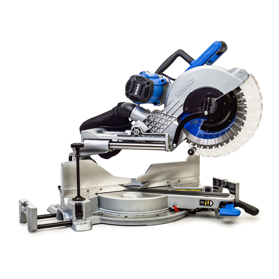
12-IN COMPACT SLIDING
DUAL-BEVEL MITER SAW
MFG Date
1
MODEL #SM3018LW
Purchase Date
ITEM #5034337
Español p. 45
Advertisement

Related Manuals for Kobalt SM3018LW


Summary of Contents for Kobalt SM3018LW
- Page 1 ITEM #5034337 12-IN COMPACT SLIDING DUAL-BEVEL MITER SAW MODEL #SM3018LW Español p. 45 KOBALT and logo design are trademarks or registered trademarks of LF, LLC. All rights reserved. ATTACH YOUR RECEIPT HERE Serial Number MFG Date Purchase Date Questions, problems, missing parts? Before returning to your retailer, call our customer service department at 888-3KOBALT (888-356-2258), 8 a.m.
- Page 2 TABLE OF CONTENTS Package Contents........................General Power Tool Safety Warnings..................Electrical Safety Information..................... 11 Preparation..........................13 Assembly Instructions....................... 14 Adjustment Instructions......................16 Operating Instructions....................... 24 Crown Molding Chart......................Care and Maintenance......................38 Troubleshooting........................40 Replacement Parts List......................Warranty............................ 44 PRODUCT SPECIFICATIONS MOTOR CUTTING CAPACITY Forward fence position:...
- Page 3 PACKAGE CONTENTS UNPACKING YOUR MITER SAW WARNING To avoid injury from unexpected starting or electrical shock, do not plug the power cord into a source of power during unpacking and assembly. The cord must remain unplugged whenever you are adjusting/assembling the saw. 1.
- Page 4 KNOW YOUR MITER SAW...
- Page 5 PART DESCRIPTION QUANTITY Carrying handle Switch handle Lower blade guard Fence Right extension wing Extension locking levers Miter lock handle Miter angle pointer Left extension wing Sliding fences Right bevel detent pin Carbon brushes Motor Hold-down latch Sliding carriages Slide carriage lock knob Bevel scale Hand-hold for transportation Mounting holes...
- Page 6 GENERAL POWER TOOL SAFETY WARNINGS WARNING power tool. serious injury. The term "power tool" in the warnings refers to your mains-operated (corded) power tool or battery-operated (cordless) power tool. Work area safety Keep work area clean and well lit. Cluttered or dark areas invite accidents. Power tools create sparks which may ignite the dust or fumes.
- Page 7 Protective equipment such as dust mask, non-skid safety shoes, hard hat, or hearing protection used for appropriate conditions will reduce personal injuries. connecting to power source and/or battery pack, picking up or carrying the tool. switch on invites accidents. A wrench or a key left attached to a rotating part of the power tool may result in personal injury.
- Page 8 Use the power tool, accessories and tool bits etc. in accordance with these instructions, taking into account the working conditions and the work to be performed. Use of the Keep handles and grasping surfaces dry, clean and free from oil and grease. Slippery handles and grasping surfaces do not allow for safe handling and control of the tool in unexpected situations.
- Page 9 Do not use the saw until the table is clear of all tools, wood scraps, etc., except for the workpiece. Small debris or loose pieces of wood or other objects that contact the revolving blade can be thrown with high speed. Cut only one workpiece at a time.
- Page 10 PROPOSITION 65 WARNING WARNING Drilling, sawing, sanding or machining wood products can expose you to wood dust, a substance known to the State of California to cause cancer. Avoid inhaling wood dust or use a dust mask or other safeguards for personal protection. For more information go to: www.P65Warnings.ca.gov/wood Some examples of these chemicals are: Lead from lead-based paints,...
- Page 11 ELECTRICAL SAFETY INFORMATION ELECTRICAL SPECIFICATIONS AND SAFETY POWER SUPPLY AND MOTOR CAUTION The A/C motor used in this saw is a universal, nonreversible type. See “MOTOR” in the “PRODUCT SPECIFICATIONS” section on page 2. protection. Your saw is wired at the factory for 120 V operation. Connect to a 120 V, 15 A circuit and use a 20 A time-delay fuse or circuit breaker.
- Page 12 FUSES may “blow” or circuit breakers may trip frequently if: MOTOR is overloaded – overloading can occur if you feed too rapidly or make too many starts/stops in a short time. LINE VOLTAGE is more than 10% above or below the nameplate voltage rating. For heavy IMPROPER or dull saw blades are used.
- Page 13 PREPARATION Before beginning assembly or operation of the product, make sure all parts are present. Compare parts with package contents list and diagram on page 3. If any part is missing or damaged, do not attempt to assemble, install or operate the product. Estimated Assembly Time: 10 minutes.
- Page 14 ASSEMBLY INSTRUCTIONS WARNING To avoid injury, do not connect this miter saw to a power source until it is completely assembled and adjusted and you have read and understood the operator’s manual. UNLOCKING THE SLIDE CARRIAGE (FIG. 1) The slide carriage lock knob (T) is located on the right side of the slide carriage.
- Page 15 INSTALLING THE HOLD-DOWN CLAMP (FIG. 4) NOTE: There are two mounting holes for the hold-down clamp. These are located just behind the fence on the left and right side of the base. Loosen the lock knob (1) behind the fence. Place the hold-down clamp assembly (B) in the desired mounting holes.
- Page 16 ADJUSTMENT INSTRUCTIONS REMOVING AND INSTALLING THE TABLE INSERTS (FIG. 5) NOTE: The miter saw comes with the table inserts already installed. These instructions are for replacing or adjusting the inserts. WARNING Always unplug the saw to avoid accidental starting. Remove all small pieces of material from the table cavity before performing any cuts.
- Page 17 MOUNTING THE MITER SAW (FIG. 6, 7, 8) WARNING To avoid injury from unexpected saw movement: Disconnect the power cord from the outlet and lock the cutting head in the lower position using the hold-down latch. Lock the slide carriage in place by tightening the slide carriage lock knob.
- Page 18 REMOVING AND INSTALLING THE BLADE WARNING Use only a saw blade diameter in accordance with the markings on the saw. Only use 12 in. diameter blade with a 1 in. arbor hole and an operating speed of more than 4,200 RPM. Do not use blades with deep guard, causing damage to the machine and/or serious injury.
- Page 19 INSTALLING THE BLADE (FIG. 9, 10, 11, 12, 13) Unplug the miter saw before changing/installing the blade. Install a 12 in. blade with a 1 in. arbor, using the provided blade insert sleeve (7) to match the 5/8 in. motor arbor. Make sure the rotation arrow on the blade matches the clockwise rotation arrow on the upper guard.
- Page 20 UNLOCKING AND LOCKING THE CUTTING HEAD (FIG. 14) Unlocking the cutting head: To raise the cutter head from its storage/transport position, push down slightly on the switch handle (F). Pull out the hold-down latch (R). Allow the cutting head to rise to the up position. Locking the cutting head: When transporting or storing the miter saw, the cutting head should always be locked in the down...
- Page 21 90° When the blade is exactly 90° to the table, loosen the bevel pointer screws (1) using a Phillips screwdriver. Adjust bevel pointers (2) to the “0” mark on the bevel scale and retighten the screw. WARNING To avoid injury from an accidental start, make sure the switch is in the OFF position and the plug is not connected to the power source outlet.
- Page 22 MITER SCALE (FIG. 18) The sliding compound miter saw scale can be easily read, showing miter angles from 0° to 55° left and 0° to 60° right. The most common angle settings have positive stops at 0°,15°, 22.5°, 31.6°, 45° left and right, 55°...
- Page 23 REMOVING OR INSTALLING THE SLIDING FENCE (FIG. 20) At some extreme angles, the right or left side fence might have to be removed to ensure proper clearance prior to making the cut. CAUTION The right/left side sliding fence must be removed when making right/left bevel angle cuts greater than 33.9°...
- Page 24 OPERATING INSTRUCTIONS BEFORE USING THE MITER SAW WARNING To avoid mistakes that could cause serious, permanent injury, do not plug the tool in until the following steps are completed: Completely assemble and adjust the saw, following the instructions (SEE ASSEMBLY AND ADJUSTMENTS SECTIONS).
- Page 25 KEEP YOUR WORK AREA CLEAN Cluttered areas and benches invite accidents. WARNING or gases. Plan ahead to protect your eyes, hands, face and ears. from accidental contact with moving parts, do not layout, assemble or set up work on the miter saw.
- Page 26 the cut. Make sure there is no debris between the workpiece and the table or fence. Make sure there are no gaps between the workpiece, fence and table that will let the workpiece shift after it is cut. against the blade and thrown violently. Only the workpiece should be on the saw table.
- Page 27 BODY AND HAND POSITION (FIG. 22) WARNING Never place hands near the cutting area. Proper positioning of your body and hands when operating the miter saw will make cutting easier and safer. Keep children away. Keep all visitors at a safe distance from the miter saw. Make sure bystanders are clear of the saw and workpiece.
- Page 28 BASIC SAW OPERATIONS WARNING For your convenience, your saw has an electric brake. The brake is not a safety device. Never rely on it to replace the proper use of the guard on your saw. If the blade does not stop within 5 seconds, unplug the saw and follow the instructions in TROUBLESHOOTING.
- Page 29 SLIDING CARRIAGE SYSTEM (FIG. 24) CAUTION to the full rear position after each crosscut operation. For chop cutting operations on small workpieces, slide the cutting head assembly completely toward the rear of the unit and tighten the slide carriage lock knob (T). To cut wide boards up to 14 in., the carriage lock knob must be loosened to allow the cutting head to slide freely.
- Page 30 MITER CUT (FIG. 26) When a miter cut is required, unlock the miter table by lifting up the miter lock handle (K). Rotate the miter table to the right or left with the miter handle. When the table is in the desired position, as shown on the miter scale (1), pressing down the miter handle to make it in a horizontal position to tighten the miter table.
- Page 31 COMPOUND CUT (FIG. 28) WARNING The right/left side sliding fence must be removed when making any bevel angle cuts greater than 33.9° in combination with any miter angle cuts greater than 31.6°. A compound cut is the combination of a miter and a bevel cut simultaneously.
- Page 32 FENCE SET UP FOR WIDE CROSSCUTS (FIG. 30, 31) This saw can cut dimensional lumber up to 2 x 16 in. when the fence is placed in its back position. Please follow the below steps for this fence set up. WARNING To avoid injury from an accidental start, make sure the switch is in the OFF position and the...
- Page 33 CUTTING BOWED MATERIAL (FIG. 32) A bowed workpiece must be positioned against the fence and secured with a clamp (B) before cutting as shown. Do not position workpiece incorrectly or try to cut the workpiece without the support of the fence. This will cause the blade to bind and could result in personal injury.
- Page 34 AUXILIARY WOOD FENCE (FIG. 35) When making multiple or repetitive cuts that piece and throw it out of the saw or into the blade Auxiliary guard and housing, possibly causing damage or fence injury. To minimize this, an auxiliary wood fence can be mounted to your saw.
- Page 35 CUTTING CROWN MOLDING (FIG. 37, 38) Your compound miter saw is suited for the properly, crown molding must be compound- mitered with extreme accuracy. The two surfaces the ceiling and wall are at angles that, when Workpiece Workpiece Most crown molding has a top rear angle (the Miter saw table Miter saw table against the wall) of 38°.
- Page 36 NOTE: The chart below references a compound cut for crown molding ONLY WHEN THE ANGLE BETWEEN THE WALLS EQUALS 90°. BEVEL MITER TYPE OF CUT SETTING SETTING Inside corner - Left side 1. Position top of molding against fence. 33.9° 31.6°...
- Page 37 CROWN MOLDING CHART Compound Miter Saw 52/38° Crown Molding 45/45° Crown Molding Angle Miter Bevel Miter Bevel Between Wall to Crown Molding Angle Setting Setting Setting Setting Walls 52/38° Crown Molding 45/45° Crown Molding 18.48 22.09 21.00 19.72 Angle Miter Bevel Miter Bevel...
- Page 38 CARE AND MAINTENANCE WARNING gasoline, naphtha, acetone, lacquer thinner or similar highly volatile solvents to clean the miter saw. To avoid injury from unexpected starting or electrical shock, unplug the power cord before working on the saw. For your safety, this saw is double insulated. the parts list.
- Page 39 SAWDUST the movement of the worktable when setting up a miter cut. Frequently blow out or vacuum up the sawdust. CAUTION If blowing sawdust, wear proper eye protection to keep debris from blowing into eyes. FREE WARNING LABEL REPLACEMENT: If your warning labels become illegible or are missing, call 888-356-2258 for a free replacement.
- Page 40 TROUBLESHOOTING WARNING To avoid injury from accidental starting, always ensure switch is in the OFF position and unplug the tool before moving, replacing the blade or making adjustments. TROUBLESHOOTING – MOTOR PROBLEM POSSIBLE CAUSE CORRECTIVE ACTION Blade does not 1. Motor brushes not sealed or 1.
- Page 41 REPLACEMENT PARTS LIST For replacement parts, call our customer service department at 888-3KOBALT (888-356-2258), 8 a.m. - 8 p.m., EST, Monday - Sunday. You could also contact us at partsplus@lowes.com. PART DESCRIPTION PART # Hold-down clamp 3VMS Dust bag 3YSA Blade wrench 3VJN Carrying handle...
- Page 42 PAGE INTENTIONALLY LEFT BLANK...
- Page 43 PAGE INTENTIONALLY LEFT BLANK...
- Page 44 WARRANTY proven to be defective in their manufacture or workmanship for a period of THREE (3) years from the date of initial retail purchase. This warranty is valid only to the original purchaser. This warranty is not transferable and does not cover any parts that have been subjected to misuse, abuse, alteration, overload, accident or normal wear of moving parts.
Need help?
Do you have a question about the SM3018LW and is the answer not in the manual?
Questions and answers