
Related Manuals for Lanner VP-501


Summary of Contents for Lanner VP-501
- Page 1 VP-501 User Manual Network Appliance Platforms Hardware Platforms for Network Computing VP-501 User Manual Version: 1.1 Date of Release: 2024-02-01...
- Page 2 - assumed to be qualified in the servicing of computer equipment, such as professional system integrators, or service personnel and technicians. The latest version of this document can be found on Lanner’s official website, available either through the product page or through the Lanner Download Center page with a login account and password.
- Page 3 VP-501 User Manual Contact Information Taiwan Corporate Headquarters China Lanner Electronics Inc. Beijing L&S Lancom Platform Tech. Co., Ltd. 7F, No.173, Sec.2, Datong Rd. Guodong LOFT 9 Layer No. 9 Huinan Road, Xizhi District, New Taipei City 22184, Huilongguan Town, Changping District, Beijing...
- Page 4 VP-501 User Manual Acknowledgment NXP® are trademarks of NXP Semiconductors N.V. or its subsidiaries in the U.S. and/or other countries. Microsoft Windows and MS-DOS are registered trademarks of Microsoft Corp. All other product names or trademarks are properties of their respective owners.
- Page 5 VP-501 User Manual N’effectuez aucune action qui pourrait créer un danger pour d’autres ou rendre l’équipement dangereux. Coupez complètement l’alimentation en éteignant l’alimentation et en débranchant le cordon d’alimentation avant d’installer ou de retirer un châssis ou de travailler à proximité de sources d’alimentation.
- Page 6 The installation of this product must be performed by trained specialists; otherwise, a non-specialist might create the risk of the system’s falling to the ground or other damages. Lanner Electronics Inc. shall not be held liable for any losses resulting from insufficient strength for supporting the system or use of inappropriate installation components.
- Page 7 VP-501 User Manual Electrical Safety Instructions Before turning on the device, ground the grounding cable of the equipment. Proper grounding (grounding) is very important to protect the equipment against the harmful effects of external noise and to reduce the risk of electrocution in the event of a lightning strike.
-
Page 8: Table Of Contents
VP-501 User Manual Table of Contents Chapter 1: Product Overview ............10 Main Features ..........................10 Package Content ..........................10 Ordering Information ........................10 Optional Accessories ........................10 System Specifications ........................11 Front Panel ............................. 12 Rear Panel ............................13 Chapter 2: Motherboard Information .......... - Page 9 VP-501 User Manual Build the System Software ......................44 Appendix A: LED Indicator Explanations .......... 47 Appendix B: Terms and Conditions ........... 49 Warranty Policy ..........................49...
-
Page 10: Chapter 1: Product Overview
VP-501 User Manual CHAPTER 1: PRODUCT OVERVIEW The VP-501, a 1U network security platform with NXP® Layerscape® LX2160 CPU, is designed for networking, industrial applications and virtualized networks and embedded systems that require an advanced data path and network peripheral interfaces. -
Page 11: System Specifications
VP-501 User Manual System Specifications Form Factor 1U 19” Rackmount CPU Processor NXP® LX2160SE72029B SOC CPU TDP Up to 27.2W Platform CPU Socket BGA1517 onboard Chipset BIOS AMI SPI Flash BIOS Technology DDR4 2900 MHz SODIMM System Memory Max. Capacity... -
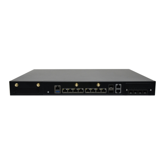
Page 12: Front Panel
VP-501 User Manual Front Panel Description Antenna 4x SMA Antenna Holes for LTE/5G Module (Optional) LED Indicators Power/Status/HDD LED Indicators, refer to Appendix A Power Switch 1x Power ON/OFF Switch Reset Button 1x Reset Button Console Port 1x RJ45 Console Port USB Port 1x USB 3.0 Ports... -
Page 13: Rear Panel
VP-501 User Manual Rear Panel Description Ground Screw 1x Grounding Hole/Screw ESD Screw 1x ESD Jack Cooling Fan 3x Cooling Smart Fans Power Switch 1x ATX Slim Type Power Switch Power Supply 1x 300W Single PSU... -
Page 14: Chapter 2: Motherboard Information
VP-501 User Manual CHAPTER 2: MOTHERBOARD INFORMATION Block Diagram... -
Page 15: Jumpers And Connectors
VP-501 User Manual Jumpers and Connectors The following displays the connectors and jumpers on the motherboard layout. - Page 16 VP-501 User Manual Jumper Setting and Connector Pin-out The following references the pin assignments and internal connectors of VP-501. SW_RCW_SRC [3:0] Function 0000 Hard-coded RCW 1000 SDHC1 SD Card 1111 Booting XSPI NOR sw_reset_mode Function Ignore RESET_REQ_B Trigger system reset on RESET_REQ_B...
- Page 17 VP-501 User Manual SW2_5 Function Unused sw_sysclk_diff Function Extended DDR reset timing Standard DDR reset timing sw_enguse[1] Function Unused sw_enguse[2] Function Single Ended DDRCLK Use Differential SYSCLK Sw_testsel_b + sw_svr[0:1] Function reserved LX2120A/E LX2080C/E LX2160A/E ...
- Page 18 VP-501 User Manual sw_bypass_b Function Disable thermal monitors and other alarms Normal Operation sw_auto_on Function Normal power on/off Always power up sw_cfg_wp Function Allow write to SYSID and UEFI flash Write protect SYSID and UEFI flash sw_tbscan...
- Page 19 VP-501 User Manual JRCW0 (Do Not Use Jumper) Description UART2_SOUT JRCW1 (Do Not Use Jumper) Description UART1_SOUT JRCW2 (Do Not Use Jumper) Description ASLEEP JRCW3 (Do Not Use Jumper) Description CLKOUT JRESET1 Description HW_RST RSTBTN_N SW_RST Jumper: 1-2 Hardware Reset (Default)
- Page 20 VP-501 User Manual Description AUDIO_0 1.8V Description AUDIO_1 3.3V Description AUDIO_2 3.3V Description DEVSLP 3.3V Description DEVSLP 3.3V JCPLD1 Description JTAG_PLD_TCK JTAG_PLD_TMO +P3V3_AUX_CPLD JTAG_PLD_TMS JTAG_PLD_TDI...
- Page 21 VP-501 User Manual JCLK1 Description 8T49N285_SCL 8T49N285_SCL +P5V +P5V JPSON1 Description ATX_ON_B JPWR2 Description PWRBTN_N FAN1 Description CPUFANOUT1_R CPUFANIN_R +P12V_ATX FAN2 Description CPUFANOUT2_R AUXFANIN0_R +P12V_ATX...
- Page 22 VP-501 User Manual FAN3 Description CPUFANOUT3_R AUXFANIN1_R +P12V_ATX JTAG1 Description JTAG_VREF PROC_TMS PROC_TCK PROC_TDO PROC_TDI JTAG_RST_B Description +P1V8_NOR XSPI_A_CS0_B +P1V8_NOR XSPI_A_D1 XSPI_A_D3 XSPI_A_D2 XSPI_A_SCK XSPI_A_D0...
-
Page 23: Chapter 3: Hardware Setup
VP-501 User Manual CHAPTER 3: HARDWARE SETUP To reduce the risk of personal injury, electric shock, or damage to the system, please remove all power connections to shut down the device completely and wear ESD protection gloves when handling the installation steps. -
Page 24: Installing The System Memory
VP-501 User Manual Installing the System Memory The motherboard supports two memory slots for DDR4 2900MHz SO-DIMM for additional system memory expansion. Please follow the steps below to install the DIMM memory module. 1. Power off the system, turn the system around, and open the chassis cover. -
Page 25: Installing M.2 Storage Module (Optional)
VP-501 User Manual Installing M.2 Storage Module (Optional) The system supports one M.2 slot for additional data storage. Please follow the steps for installation. 1. Power off the system and open the chassis cover. 2. Locate the M.2 slot on the motherboard. -
Page 26: Installing Lte/5G Module Card (Optional)
VP-501 User Manual Installing LTE/5G Module Card (Optional) The motherboard provides one M.2 slot for an LTE/5G module card expansion. An LTE module will require two (2) antennas, and a 5G module requires four (4) antennas. Please follow the steps for installation. - Page 27 VP-501 User Manual Installing 5G Antennas Front Panel 1. Locate the four (4) antenna hole placement (A1, A2, A3, A4). Locate the four (4) antenna IPEX connectors on the 5G module card. 2. Connect the RF cables to the IPEX connectors on the 5G module card and screw the other end of the...
- Page 28 VP-501 User Manual 3. Then, screw on the four (4) antennas on the outside of the system. Installing LTE Antennas Front Panel 1. Locate the two (2) antenna hole placement (A1, A2). Locate the two (2) antenna IPEX connectors on the LTE module card.
- Page 29 VP-501 User Manual Installing SIM Cards The dual SIM card slot supports the LTE/5G module card. Please follow the steps below for SIM card placement. 1. Locate the SIM slots next to the LTE/5G module on the motherboard. 2. Insert and push the SIM card, gold contacts facing downwards, all the way in until it clicks into place.
-
Page 30: Installing Disk Drive(S) (Optional)
VP-501 User Manual Installing Disk Drive(s) (Optional) The HDD/SSD bay supports one 2.5” SATA HDD/SSD for additional data storage. Please follow the steps below for installation. 1. Power off the system and open the chassis cover. 2. Locate the disk tray placement inside the system. - Page 31 VP-501 User Manual 5. Place the tray (with the disk drive now installed) back to its original place inside the system. Secure with the original three (3) screws. Attach the SATA data cable and power cable to the HDD/SSD. 6. Then, insert the other end of the SATA data...
-
Page 32: Installing Nic Modules (Optional)
VP-501 User Manual Installing NIC Modules (Optional) VP-501 comes with one NIC module slot for expansion. Follow the stems for installation. 1. Locate the NIC module slot on the front panel of the system. 2. Rotate clockwise and loosen the two (2) lock- screws, and remove the NIC module slot door. -
Page 33: Mounting The System
VP-501 User Manual Mounting the System There are two methods for installing this system into a rack: With Mounting Ear Brackets only This method is quick and easy by fixing this system to the front posts of the rack, but it also makes servicing the system more difficult. - Page 34 VP-501 User Manual Installing the System Using Mounting Ear Brackets Only 1. Check the accessory pack for the following items: 1x Screw Pack 2x Ear Brackets Screw Pack Ear Brackets 2. Align the bracket to the side of the chassis and...
- Page 35 VP-501 User Manual Installing the System Using the Slide Rail Kit (with Mounting Ear Brackets) 1. Check the package contents of the Slide Rail Kit. The kit shall include the following items: 1x pack of M4X4L screws (for 7.1 Round Hole Screws...
- Page 36 VP-501 User Manual 5. Align the bracket to the side of the chassis and make sure the screw- holes are matched, and then secure the bracket onto the chassis with three provided M4X4L screws. Align the screws with the holes indicated on the brackets and the screw holes on the side of the chassis.
- Page 37 VP-501 User Manual 9. For the rear rack installation, slide the rail to aim and engage the bolts on the rail’s rear end with the two available holes on the post, and the rail assembly will click into place. Click 10.
- Page 38 VP-501 User Manual 12. While pushing in the system, also push and hold the Rail Lock tab on both brackets. Rail Lock Push the system all the way in until it stops. To remove the system from the rack, gently pull it outwards, towards you, while pushing the Release Tab on both sides of the brackets.
-
Page 39: Chapter 4: Software Setup
By downloading LSDK source code from the NXP official website and applying the software patch file for Lanner VP-501, then you can compile three types of images: bootloader, Linux kernel, and root filesystem. After burning these three images onto an SD card, you can boot the VP-501 system using the compiled software. -
Page 40: Create A Boot Disk
Create a Boot Disk Preparatory Work 1. The NOR-Flash on the VP-501 board already has the bootloader pre- burned. DIP switch SW1 must be set to 1111 as shown in the diagram to boot from NOR-Flash. 2. When connecting the computer's COM port to the board's console port, the speed setting in the... - Page 41 3. If the DIP switch SW1 are set correctly, the console should display the following messages when the VP- 501 board is powered on. 4. The boot disk options for the VP-501 board include the following choices. This document explanation uses the SD card as an example.
-
Page 42: Burn The Sd Card Image File
VP-501 User Manual Burn the SD Card Image File 1. Install Win32DiskImager 2. Insert the SD card into the PC. 3. Run Win32DiskImager 4. Select the sdcard.img downloaded from Lanner website. - Page 43 VP-501 User Manual 5. Write the image to the SD card. 6. After the burning process is complete, you can then insert the SD card into VP-501 to boot up the system. 7. Successful Boot-up...
-
Page 44: Build The System Software
VP-501 User Manual Build the System Software 1. Download NXP LSDK: flexbuild_lsdk2108_github.tgz from website: https://lsdk.github.io/components.html 2. Build Source Code [boot package] ~# tar xvfz flexbuild_lsdk2108_github.tgz ~# cd flexbuild_lsdk2108_github ~# source setup.env ~# flex-builder -c ddr_phy_bin -m lx216ardb_rev2 ~# flex-builder -c dp_firmware_cadence -m lx2160ardb_rev2... - Page 45 ~# flex-builder -c ovs_dpdk -r ubuntu:main ~# flex-builder -c aiopsl -r ubuntu:main ~# flex-builder -i merge-component -r ubuntu:main ~# flex-builder -i packrfs -r ubuntu:main 3. Patch Following Lanner VP-501 Code to LSDK ~# cd flexbuild_lsdk2108_github/configs/board ~# patch -p1 -f -i $(your_folder)/board.patch ~# cd flexbuild_lsdk2108_github/components/linux/linux ~# patch -p1 -f -i $(your_folder)/linux.patch...
- Page 46 5. Burn All Image to SD Card (in case SD Card is /dev/sdb) ~# flex-installer -i pf -d /dev/sdb ~# flex-installer -f firmware_lx2160ardb_rev2_sdboot.img -b boot_LS_arm64_lts_5.10.tgz -r rootfs_lsdk2108_ubuntu_main_arm64.tgz - d /dev/sdb 6. Insert the SD Card into VP-501 to Boot Up System...
-
Page 47: Appendix A: Led Indicator Explanations
VP-501 User Manual APPENDIX A: LED INDICATOR EXPLANATIONS The status explanations of LED indicators on Front Panel are as follows: Green: System Power Red/Green: System Status Amber: HDD Activity COLOR LED ACTION DESCRIPTION Green Steady System is powered ON Power... - Page 48 VP-501 User Manual 10Gb SFP+ Light pipe LED (top location) Define: Speed Amber (Active) Amber Green (Link) Blinking / Data access ON (Amber) Blinking / Steady ON (Green) Non-Link 1. When cable is plug-in and network is linked. Both LED will be bright. The behavior is as defined.
-
Page 49: Appendix B: Terms And Conditions
VP-501 User Manual APPENDIX B: TERMS AND CONDITIONS Warranty Policy 1. All products are under warranty against defects in materials and workmanship for a period of one year from the date of purchase. 2. The buyer will bear the return freight charges for goods returned for repair within the warranty period;... - Page 50 VP-501 User Manual RMA Service Request Form When requesting RMA service, please fill out the following form. Without this form enclosed, your RMA cannot be processed.
Need help?
Do you have a question about the VP-501 and is the answer not in the manual?
Questions and answers