
Related Manuals for Lanner VP-210


Summary of Contents for Lanner VP-210
- Page 1 Network Appliance Platforms Hardware Platforms for Network Computing VP-210 User Manual Version: 1.0 Date of Release: 2024-11-05...
-
Page 2: About This Document
- assumed to be qualified in the servicing of computer equipment, such as professional system integrators, or service personnel and technicians. The latest version of this document can be found on Lanner’s official website, available either through the product page or through the Lanner Download Center page with a login account and password. -
Page 3: Contact Information
VP-210 User Manual Contact Information Taiwan Corporate Headquarters China Lanner Electronics Inc. Beijing L&S Lancom Platform Tech. Co., Ltd. 7F, No.173, Sec.2, Datong Rd. Guodong LOFT 9 Layer No. 9 Huinan Road, Xizhi District, New Taipei City 22184, Huilongguan Town, Changping District, Beijing... -
Page 4: Federal Communication Commission Interference Statement
VP-210 User Manual Acknowledgment NXP® are trademarks of NXP Semiconductors N.V. or its subsidiaries in the U.S. and/or other countries. Microsoft Windows and MS-DOS are registered trademarks of Microsoft Corp. All other product names or trademarks are properties of their respective owners. -
Page 5: Safety Guidelines
VP-210 User Manual Safety Guidelines Follow these guidelines to ensure general safety: Keep the chassis area clear and dust-free during and after installation. Do not wear loose clothing or jewelry that could get caught in the chassis. Fasten your tie or scarf and roll up your sleeves. -
Page 6: Sécurité De Fonctionnement
The installation of this product must be performed by trained specialists; otherwise, a non-specialist might create the risk of the system’s falling to the ground or other damages. Lanner Electronics Inc. shall not be held liable for any losses resulting from insufficient strength for supporting the system or use of inappropriate installation components. -
Page 7: Electrical Safety Instructions
VP-210 User Manual Electrical Safety Instructions Before turning on the device, ground the grounding cable of the equipment. Proper grounding (grounding) is very important to protect the equipment against the harmful effects of external noise and to reduce the risk of electrocution in the event of a lightning strike. -
Page 8: Table Of Contents
VP-210 User Manual Table of Contents Chapter 1: Product Overview ............10 Package Content ..........................10 Ordering Information ........................10 Optional Accessories ........................10 System Specifications ........................11 Front Panel ............................. 12 Chapter 2: Motherboard Information ..........14 Jumper Setting and Connector Pin-out ..................15 Chapter 3: Hardware Setup ............... - Page 9 VP-210 User Manual Burn EMMC Flash ........................... 35 Update Bootloader Image via U-Boot .................... 36 Testbed Program ..........................37 Ethernet Port Number ........................38 LED Control ............................. 39 Fan Control ............................. 40 Appendix A: LED Indicators ............... 41 Appendix B: Terms and Conditions ........... 43...
-
Page 10: Chapter 1: Product Overview
VP-210 User Manual CHAPTER 1: PRODUCT OVERVIEW The VP-210’s processing prowess, hardware acceleration, industry-leading I/O, and DDR5 support together make it the ideal hardware solution that addresses the growing requirements for network, storage and security processing among cloud service providers, telecommunications carriers and enterprises. -
Page 11: System Specifications
VP-210 User Manual System Specifications Form Factor Desktop CPU Processor Marvell OCTEON CN102 Series CPU TDP 2.5GHz, 37W / 1.6GHz, 24W (By SKU) Platform CPU Socket Onboard Security Acceleration Crypto 50G IMIX Unidir + ~ 12K RSA 2K OPS BIOS... -
Page 12: Front Panel
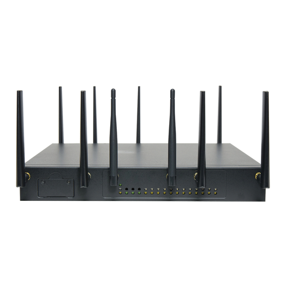
VP-210 User Manual Front Panel Description Power Switch 1x Power ON/OFF Switch Reset Button 1x Reset Button 2x DC Jack Power-IN (SKU A); Power Inlet 1x DC Jack Power-IN (SKU B) Console Port 1x RJ45 Console Port USB Port 1x USB 3.0 Port... - Page 13 VP-210 User Manual Rear Panel Description SIM Cover 2x Nano SIM Slots w/ Cover LED Indicators LED Indicators for Status/Wi-Fi/LTE/5G LED Indicators LED Indicators (Reserved, By Project) Antenna 6x SMA Antenna Holes...
-
Page 14: Chapter 2: Motherboard Information
VP-210 User Manual CHAPTER 2: MOTHERBOARD INFORMATION Block Diagram 88X3310P 88X3310P... -
Page 15: Jumper Setting And Connector Pin-Out
VP-210 User Manual Jumper Setting and Connector Pin-out The following displays the connectors and jumpers on the motherboard layout. - Page 16 VP-210 User Manual JRESET1 Pin No. Description HW Reset SW Reset Description Pin No. eMMC Boot NOR Flash Boot FN980/FN990 FN980/FN990 EM9191X/EM7690/ EM9191X/EM7690/ Pin No. Description PCIe EM929X USB EM929X PCIe JM2 USB Mode JM2 PCIe Mode FN980/FN990 FN980/FN990 EM9191X/EM7690/ EM9191X/EM7690/ Pin No.
- Page 17 VP-210 User Manual Pin No. Description EM7690 EM929X/EM9191/EM9190 FN980/FN990 M2_VBUS_SENSE M2_EM9291_VCC1_1 M2_EM9291_VCC2_1 9-10 M2_EM9291_VCC3_1 J26, J24, J27 Pin No. Description J26,J24,J27 SIM1 on JM3, SIM2 on JM2 SIM1, SIM2 on JM3...
-
Page 18: Chapter 3: Hardware Setup
VP-210 User Manual CHAPTER 3: HARDWARE SETUP To reduce the risk of injury, electric shock, or system damage, disconnect all power and wear ESD protection gloves during installation. Opening the Chassis 1. Power off the system. 2. Locate and remove the two (2) screws on the chassis cover. -
Page 19: Installing The System Memory
VP-210 User Manual Installing the System Memory The motherboard supports one DDR5 SODIMM system memory. Please follow the steps below to install the DIMM memory module. 1. Power off the system and open the chassis cover. 2. Locate the system memory slot on the motherboard. -
Page 20: Installing M.2 Storage Module (Optional)
VP-210 User Manual Installing M.2 Storage Module (Optional) The system supports one M.2 M-Key slot for additional storage. Please follow the steps for installation. 1. Power off the system and open the chassis cover. 2. Locate the M.2 slot on the motherboard. -
Page 21: Installing Wi-Fi Module Card (Optional)
VP-210 User Manual Installing Wi-Fi Module Card (Optional) The system supports one M.2 slot for a Wi-Fi module expansion. Wi-Fi module requires two antennas. Please follow the steps to install the Wi-Fi module card. 1. Power off the system and open the chassis cover. -
Page 22: Installing Lte/5G Module Card (Optional)
VP-210 User Manual Installing LTE/5G Module Card (Optional) The motherboard provides two M.2 B-Key slots for LTE/5G module card expansion. An LTE module requires two antennas, while a 5G module will require four antennas. Please follow the procedures for installation. -
Page 23: Installing Sim Card (Optional)
VP-210 User Manual Installing SIM card (Optional) The SIM slot on the front panel supports the LTE/5G module card. Please follow the steps below for SIM card placement. 1. Power off the system. 2. Locate the SIM slot cover. Unscrew the two (2) screw securing the cover. -
Page 24: Installing Poe Module Kit (Optional)
VP-210 User Manual Installing PoE Module Kit (Optional) The motherboard supports one PoE module slot. Please follow the steps below to install the PoE kit. 1. The PoE Module Kit includes: 1x PoE Module 3x Spacer standoff pillar studs 1x Power Adapter... - Page 25 VP-210 User Manual 7. Screw in the original three (3) screws to secure the PoE module board. Front Panel View 8. Connect the power source pin to the power adapter.
-
Page 26: Wall Mounting (Optional)
VP-210 User Manual Wall Mounting (Optional) With the Wallmount Kit, this system can be fixed on a flat surfaced wall surface. Please contact Lanner Sales representative for purchasing this kit. The Wallmount kit includes: 1x pair of Wall Brackets 1x Screw Pack... - Page 27 VP-210 User Manual 5. Position the system's wall brackets to line up with the four screws on the wall. 6. Attach the system by aligning its bracket holes with the wall screws, then press downward on the system to secure.
-
Page 28: Mounting The System (Optional)
VP-210 User Manual Mounting the System (Optional) With a short ear rackmount kit, VP-210 can be installed into a rack. Please contact Lanner’s sales representative for purchasing the short ear rackmount kit. The Short Ear Rackmount Kit contains the following:... -
Page 29: Chapter 4: Software Setup
USB flash drive or directly to the EMMC Flash. 4. Final Setup: Once both image files have been successfully flashed, the VP-210 board will have the Bootloader and Ubuntu 20.04 operating system installed, allowing it to be used for testbed testing or software application evaluation. -
Page 30: Burn Bootloader Image
3. The programmer used for this process is the DediProg SF700. 4. Connect the programmer to the computer via USB. 4. The VP-210 board does not need to be powered on when using the programmer. 5. The image file to be burned-in is: flash-cn10kb.img 6. - Page 31 VP-210 User Manual 7. Click ”File” to load flash-cn10kb.img file 8. Click “Erase” to clear the NOR-Flash 9. Click ”Prog” to burn the image file 10. Once the burning process is complete, disconnect the programming cable and power on the VP-210 motherboard.
-
Page 32: Set Ebf Boot Option
2. Use an RJ45 to COM port adapter for the console connection, as shown below: 3. Set the PC terminal software’s baud rate to 115200. When the VP-210 is powered on, if the board configuration area is empty, you will see an output message. Press “S” to enter the Setup menu. - Page 33 VP-210 User Manual Comparison Chart...
-
Page 34: Create Usb Boot Disk
4. You can also use the dd command in a Linux system to burn the image: # dd if=./vp210.img of=/dev/sda # sync 5. Once the USB flash drive is successfully burned, insert it into the USB port of the VP-210 board to boot the system normally. USB Boot Disk VP-210 Ubuntu 20.04... -
Page 35: Burn Emmc Flash
3. After the burning process is complete, shut down the system, remove the USB boot disk, and power it on again. The VP-210 will automatically boot into the system from EMMC Flash. 4. To verify that the system booted from EMMC, execute the following command:... -
Page 36: Update Bootloader Image Via U-Boot
1. The bootloader image compiled using the Marvell SDK is named: flash-cn10kb.img. 2. Copy flash-cn10kb.img to a USB flash drive and insert it into the USB port of the VP-210 board. 3. Power on the VP-210 and press any key to stop at the U-Boot command line. -
Page 37: Testbed Program
VP-210 User Manual Testbed Program 1. To begin testing, install the M.2 module and network cable according to the illustration provided. 2. The following modules have been verified for use with the Testbed: 5G-NR: Telit FN980 4G-LTE: Sierra EM7590 ... -
Page 38: Ethernet Port Number
VP-210 User Manual Ethernet Port Number 1. Network port numbers may vary depending on the operating system. Below are the network port numbers for the Buildroot system. 2. The corresponding network port numbers for Ubuntu 20.04 are listed below. Port... -
Page 39: Led Control
VP-210 User Manual LED Control 1. The LEDs on the VP-210, as shown in the image below, include four software-controlled LEDs: Status, Wi- Fi, 4G-LTE, and 5G-NR. 2. The Power-on LED is not software-controllable, while the Disk LED is controlled by the NVMe SSD module. -
Page 40: Fan Control
VP-210 User Manual Fan Control 1. The VP-210 manages fan control via the NCT7904 hardware monitor. You can reference the following sample code for the control method: /root/test_script/fan_control/fan_ctl.sh 2. To check the system temperature, use the sensors command. -
Page 41: Appendix A: Led Indicators
VP-210 User Manual APPENDIX A: LED INDICATORS LED Indicators Green: System Power Red/Green: System Status Amber: HDD Activity COLOR LED ACTION DESCRIPTION Green Steady System is powered ON Power System is powered OFF Green Steady LED status controlled by GPIO... - Page 42 VP-210 User Manual 10Gb RJ45 Define: Speed Green (Active) Green/Amber (Link) 10/100M Blinking / Data access Blinking / Data access ON (Amber) Blinking / Data access ON (Green) 1. When cable is plug-in and network is linked. Both LED will be bright. The behavior is as defined.
-
Page 43: Appendix B: Terms And Conditions
VP-210 User Manual APPENDIX B: TERMS AND CONDITIONS Warranty Policy 1. All products are under warranty against defects in materials and workmanship for a period of one year from the date of purchase. 2. The buyer will bear the return freight charges for goods returned for repair within the warranty period;... -
Page 44: Rma Service Request Form
VP-210 User Manual RMA Service Request Form When requesting RMA service, please fill out the following form. Without this form enclosed, your RMA cannot be processed.
Need help?
Do you have a question about the VP-210 and is the answer not in the manual?
Questions and answers