Advertisement
Quick Links
Advertisement

Subscribe to Our Youtube Channel
Related Manuals for Lanner LEC-3340


Summary of Contents for Lanner LEC-3340
- Page 1 LEC-3340 User Manual Version: 1.4 Date of Release:2022-08-29...
- Page 2 - assumed to be qualified in the servicing of computer equipment, such as professional system integrators, or service personnel and technicians. The latest version of this document can be found on Lanner’s official website, available either through the product page or through the Lanner Download Center page with a login account and password.
- Page 3 LEC-3340 User Manual Taiwan Corporate Headquarters China Lanner Electronics Inc. Beijing L&S Lancom Platform Tech. Co., Ltd. 7F, No.173, Sec.2, Datong Rd. Guodong LOFT 9 Layer No. 9 Huinan Road, Xizhi District, New Taipei City 22184, Huilongguan Town, Changping District, Beijing...
- Page 4 Intel® and Intel® Celeron® are trademarks of Intel Corporation or its subsidiaries in the U.S. and/or other countries. Microsoft Windows and MS-DOS are registered trademarks of Microsoft Corp. Hailo-8 is registered trademarks of Hailo. All other product names or trademarks are properties of their respective owners. This equipment has been tested and found to comply with the limits for a Class A digital device, pursuant to Part 15 of FCC Rules.
- Page 5 LEC-3340 User Manual Follow these guidelines to ensure general safety: Keep the chassis area clear and dust-free during and after installation. Do not wear loose clothing or jewelry that could get caught in the chassis. Fasten your tie or scarf and roll up your sleeves.
- Page 6 The installation of this product must be performed by trained specialists; otherwise, a non-specialist might create the risk of the system’s falling to the ground or other damages. Lanner Electronics Inc. shall not be held liable for any losses resulting from insufficient strength for supporting the system or use of inappropriate installation components.
- Page 7 LEC-3340 User Manual Avant d’allumer l’appareil, reliez le câble de mise à la terre de l’équipement à la terre. Une bonne mise à la terre (connexion à la terre) est très importante pour protéger l’équipement contre les effets néfastes du bruit externe et réduire les risques d’électrocution en cas de foudre.
- Page 8 Key Features ..........................9 Ordering Information ........................9 System Specifications ......................... 10 Physical Overview ........................11 Motherboard Information ......................13 Installing the System Memory ....................19 Installing Storage Module Card ....................21 Installing the Hard Disk ....................... 22 Installing the PCIe Modules ......................23 Replacing the AC/DC Power Supply Units ..................
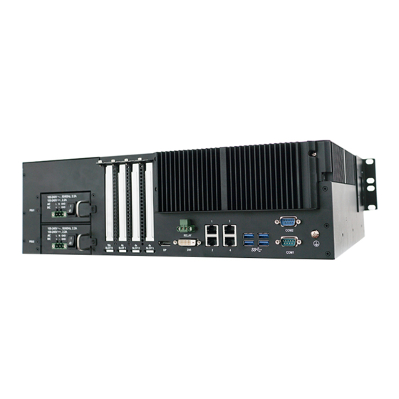
- Page 9 LEC-3340 User Manual LEC-3340, a 3U rackmount industrial edge consolidation server, is powered by Intel® Xeon® E3-1505L V6, or Core™ i5-7442EQ (formerly Kaby Lake-H) processor, to offer outstanding performance. Designed to be robust, LEC-3340 is IEC-61850 and IEEE 1613 compliant. This industrial-grade edge consolidation server provides rich I/O functions, including 4x PCIe slots, 4x RJ-45 GbE LAN ports, 5x USB 3.0 ports, 2x 2.5”...
- Page 10 Processor Options Intel® Xeon® E3-1505L V6, or Core i5-7442EQ CPU Frequency 2.2 GHz or 2.9 GHz Processor System Core Number Intel Xeon E3-1505L V6/Core i5-7442EQ: Quad core Chipset Intel® CM238 BIOS AMI SPI Flash BIOS Technology DDR4 ECC Memory Max. Capacity 32 GB Socket 2x 260-pin SODIMM...
- Page 11 LEC-3340 User Manual Description 2x 2.5” SATA HDD/SSD Bay Reset Button PWR: indicates PSU power status 1 (PSU1) 2 (PSU2) Solid Green The system is powered on The system is powered off HDD: indicates mSATA/HHD1/HHD activities Blinking Green Data access activity...
- Page 12 Description AC/DC Power Supply 2xAC PSU or 2x DC PSU 1x PCIe x16 slot + 3x PCIe x4 slot (from left to right: x16, x4, x4, x4) PCIe Slot Note: The overall power consumption of all slots shall not exceed 35W Relay Output 1x Relay Out for Power Failure Alarm 2x DB9 for RS-232/422/485 with Isolation...
- Page 13 LEC-3340 User Manual The block diagram indicates how data flows among components on the motherboard. Please refer to the following figure for your motherboard’s layout design. (Optional) TTL RS232 Reserved...
- Page 14 The motherboard layout shows the connectors and jumpers on the board. Refer to the following picture as a reference of the pin assignments and the internal connectors. FAN2 FAN1 ATX2 ATX3 JUSB1 JUSB_PW1 J80PORT1 CMOS1 SATA1 JLED1 SATA2 SATA3 JDIO1...
- Page 15 LEC-3340 User Manual ATX2&ATX3: 8 pin Power Connector Description Description Ground Ground Ground Ground SATA1 & SATA2 & SATA3: 180° SATA Connector (with SATA DOM) Description Description FAN1~2: FAN Connector Description Description RPM Sense RPM Sense PWM Status SW1: PSON power switch for debug...
- Page 16 J3: PSON power switch for debug Description Description FP_SWIN_R JLED1: Led Description Description Description Description HDD_LED_N PCH_SYS_RESET_N LAN1_L1000_N_R LAN1_L100_N_R STATUS_GLED# STATUS_RLED# LAN3_L1000_N_R LAN2_L100_N_R LAN2_L1000_N_R LAN1_ACTLED_N RX_COM1 LAN3_L100_N_R LAN4_L1000_N_R LAN2_ACTLED_N RX_COM2 LAN4_L100_N_R TX_COM1 LAN3_ACTLED_N TX_COM2 LAN4_ACTLED_N...
- Page 17 LEC-3340 User Manual COM3: COM2 PORT Description Description NDCD NDSR NRXD NRTS NTXD NCTS NDTR COM2: RS-232 Port Description Description NRXD NRTS NTXD NCTS JDIO1 : IO power Description Description 5V(S5) GPO_B_0 GPI_B_0 GPO_B_1 GPI_B_1 GPO_B_2 GPI_B_2 GPO_B_3 GPI_B_3 Ground...
- Page 18 J80PORT1: 80Port Debug Description Description LAD1 RST- LAD0 LRAME- POWER LAD3 LAD2 JUSB1: USB 3.0 Description Description...
- Page 19 LEC-3340 User Manual To reduce the risk of personal injury, electric shock, or damage to the system, please remove all power connections to shut down the device completely. Also, please wear ESD protection gloves when conducting the steps in this chapter.
- Page 20 6. Insert the DIMM card at 30 degrees into the socket until it is fully seated. 7. Push down on the module card until the Click slot latches catches and clicks into place. Click...
- Page 21 LEC-3340 User Manual The system supports one mSATA socket for additional data storage. Please follow the steps for installation. 1. Power off the system and turn the system upside down, with its bottom side facing 2. Locate the storage memory cover.
- Page 22 The system supports two externally accessible disk drive bays on the front panel. The disk drive bays also support RAID 0.1. Please follow the steps below to install or replace disk drives. 1. Locate the disk drive bays on the front panel.
- Page 23 LEC-3340 User Manual To install your PCIe modules into the slots on the system’s front panel: 1. Remove the 8 screws that secure the top cover and lift the cover up to remove it. 2. Remove the PCIe Slot cover 3.
- Page 24 Power supply units may wear down eventually. Please note that the LEC-3340 supports 2x DC or DC+AC PSU, with 100-240VAC, or 16.6-160VDC. Please prepare power supply units matching this capacity and specification. 1. Locate the power supply unit(s) on the rear panel and disconnect the power cord.
- Page 25 LEC-3340 User Manual To enter the BIOS setup utility, follow the steps below: 1. Boot up the system. 2. Pressing the <Tab> or <Del> key immediately allows you to enter the Setup utility, then you will be directed to the BIOS main screen. The instructions for BIOS navigations are as below:...
- Page 26 Setup main page contains BIOS information and project version information. (The screenshots presented in this section are for reference only) Item Description BIOS Vendor: American Megatrends Core Version: AMI Kernel version, CRB code base, X64 Compliancy: UEFI version, PI version BIOS Information Project Version: BIOS release version Build Date and Time: MM/DD/YYYY...
- Page 27 LEC-3340 User Manual Select the Advanced menu item from the BIOS setup screen to enter the “Advanced” setup screen. Users can select any of the items in the left frame of the screen.
- Page 28 Feature Options Description Intel (VMX) When enabled, a VMM can utilize the additional Disabled Virtualization hardware capabilities provided Vanderpool Enabled Technology Technology. Enabled for Windows XP and Linux (OS optimized for Disabled Hyper-Threading Technology) and Disabled for other Hyper-Threading Enabled optimized Hyper-Threading Technology).
- Page 29 LEC-3340 User Manual...
- Page 30 CPU – Power Management Control Feature Options Description Intel(R) Disabled Allows more than two frequency ranges to be SpeedStep(tm) Enabled supported. Disabled Enable/Disable CPU Power Management. Allows CPU C states Enabled to go to C states when it's not 100% utilized.
- Page 31 LEC-3340 User Manual Feature Options Description Disabled When Disabled ME will be put into ME Temporarily ME State Enabled Disabled Mode.
-
Page 32: Firmware Update Configuration
Firmware Update Configuration Feature Options Description ME FW Image Disabled Configure Management Engine Technology Parameters Re-Flash Enabled... - Page 33 LEC-3340 User Manual Feature Options Description Security Device Disable Enables or Disables BIOS support for security device. Support Enable Disabled SHA-1 PCR Bank Enable or Disable SHA-1 PCR Bank Enabled Disabled SHA256 PCR Bank Enable or Disable SHA256 PCR Bank...
- Page 35 LEC-3340 User Manual Serial port 1 Configuration Feature Options Description Disabled Serial Port Enable or Disable Serial Port 1. Enabled Device Settings IO=3F8h; IRQ = 4...
- Page 36 Serial port 2 Configuration Feature Options Description Disabled Serial Port Enable or Disable Serial Port 2. Enabled Device Settings IO=2F8h; IRQ = 3...
- Page 37 LEC-3340 User Manual Serial port 3 Configuration Feature Options Description Serial Port Disabled Enable or Disable Serial Port 3. Enabled Device Settings IO=3E8h; IRQ = 7...
-
Page 38: Cpu Vcore
Feature Description SYS1 Temp This value reports the System1 temperature. SYS2 Temp This value reports the System2 temperature. CPU Temp This value reports the CPU temperature. CPU VCORE This value reports the CPU VCORE. VCCDU This value reports the VCCDU. This value reports the 5V Input voltage. - Page 39 LEC-3340 User Manual Feature Options Description COM1 MODE Select COM1 mode as RS232/422/485 Enabled COM1 Termination It can be selected on RS422/485 mode. Disabled COM2 MODE Select COM2 mode as RS232/422/485 Enabled COM2 Termination It can be selected on RS422/485 mode.
- Page 40 Feature Options Description Status LED Configuration Status LED. GREEN...
- Page 41 LEC-3340 User Manual Feature Options Description Legacy USB Support Enables Legacy USB support. Enabled AUTO option disables legacy support if no USB Disabled devices are connected. Auto DISABLE option will keep USB devices available only for EFI applications. USB Mass Storage Enabled Enable/Disable USB Mass Storage Driver Support.
- Page 42 Select the Chipset menu item from the BIOS setup screen to enter the Chipset Setup screen. Users can select any of the items in the left frame of the screen.
- Page 43 LEC-3340 User Manual Feature Options Description Disabled VT-d VT-d capability Enabled...
-
Page 44: Memory Configuration
Memory Configuration... - Page 45 LEC-3340 User Manual Feature Options Description Quiet Serial IRQ Mode Configure Serial IRQ Mode. Continuous...
- Page 46 Feature Options Description Disabled SATA Controller(s) Enable/Disable SATA Device. Enabled AHCI SATA Mode Determines how SATA controller(s) operate. Intel RST Selection AHCI or RAID mode Premium...
- Page 47 LEC-3340 User Manual Select the Security menu item from the BIOS setup screen to enter the Security Setup screen. Users can select any of the items in the left frame of the screen. Feature Description If ONLY the Administrator's password is set, then this only...
- Page 48 Select the Boot menu item from the BIOS setup screen to enter the Boot Setup screen. Users can select any of the items in the left frame of the screen Feature Options Description The number of seconds to wait for setup activation key. Setup Prompt Timeout 65535 means indefinite waiting.
- Page 49 LEC-3340 User Manual Select the Save and Exit menu item from the BIOS setup screen to enter the Save and Exit Setup screen. Users can select any of the items in the left frame of the screen. ■Save Changes and Exit When Users have completed the system configuration changes, select this option to save the changes and Exit from BIOS Setup, so the new system configuration parameters can take effect.
-
Page 50: Chapter 3: Bios Setup
Chapter 3: BIOS Setup ■Restore Defaults Restore default values for all setup options. Select YES to load Optimized defaults. -
Page 51: Appendix A: Installing Intel® Lan Controller Driver For Linux
Appendix A: Installing Intel® LAN Controller Driver for Linux For the latest driver update, please visit Intel® download center at https://downloadcenter.intel.com/, use the keyword search or the filter to access the driver’s product page, and then download the latest controller driver as well as the ReadMe document. -
Page 52: Appendix B: Terms And Conditions
Appendix B: Terms and Conditions 1. All products are under warranty against defects in materials and workmanship for one year from the date of purchase. 2. The buyer will bear the return freight charges for goods returned for repair within the warranty period; whereas the manufacturer will bear the after service freight charges for goods returned to the user. - Page 53 Appendix B: Terms and Conditions When requesting RMA service, please fill out the following form. Without this form enclosed, your RMA cannot be processed.
Need help?
Do you have a question about the LEC-3340 and is the answer not in the manual?
Questions and answers