Table of Contents
Advertisement
Quick Links
Advertisement
Table of Contents

Related Manuals for Skov DA 50-650


Summary of Contents for Skov DA 50-650
- Page 1 DA 50-650 Technical User Guide...
-
Page 2: Table Of Contents
Measuring and Mounting of Pull Rod/Suspension ............16 2.3.15 Fastening of Air Supply Unit to Pull Rod ..............17 Adjustment of DA 50-650 Air Supply Unit ............18 INSTALLATION GUIDE Cable Chart for Recirculation Fan ..............20 Wiring Diagram for Recirculation Fan ............21 Diagram for Rotating Direction of the Recirculation Fan ......22... -
Page 3: Appendix 1
Mounting Guide, free hanging Ridge ..............30 APPENDIX 4 11.1 Mounting Guide, Roof through Garret ............32 APPENDIX 5 12.1 Mounting Guide, Ridge through Garret ............35 APPENDIX 6 13.1 Mounting Guide, Monoblock House ...............37 APPENDIX 7 14.1 Mounting Guide, flat Roof................38 DA 50-650... -
Page 4: Product Description
The DA 50 Air Supply Unit is an air inlet, which combines high output with low air velocity in the area occupied by the birds. DA 50-650 performs up to 12,250 m /h at 40 Pa negative pressure. The high output is obtained without the use of a fan. -
Page 5: Mounting Guide
Check that all ordered parts are present and intact according to the delivery note before you start your work. This chapter concerns the general mounting of the DA 50-650 unit, regardless of the type of building in which it is to be mounted. -
Page 6: Examples Of Placement In The House
Technical User´s Guide 2.2.1 Examples of Placement in the House Figure 1 Example of a 50 m long house with one winch motor. Figure 2 Example of a 100 m long house with two winch motors. DA 50-650... -
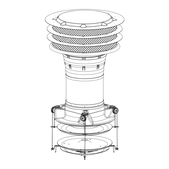
Page 7: General Mounting
Technical User´s Guide General Mounting 2.3.1 General Drawings Figure 3 DA 50-650... - Page 8 Remember that roles on the funnel tube must be turned lengthwise of the building. See section 1.2.1. Fasten the duct to the wooden frame. 3. Adapt the height of the last duct. Mount the last duct on the other ducts. Finally fasten the roof duct to the roof sheet. DA 50-650...
-
Page 9: Mounting Of Roof Sheet
Saw 40 mm off the longitudinal labyrinth lock from the top. ▪ Mount the shortened part on the bell mouth or another duct by means of eight 6×16 mm rustproof bolts with locknuts or twenty rustproof self-cutting screws of 4.2×12 mm. DA 50-650... -
Page 10: Roof Flashing With Neoprene Cloth
15cm above roof. Pull the cloth into place over the duct and spread it properly on the roof. Place the top roofing sheets over the cloth. Mount various screws for fixation of cloth and roofing sheets. DA 50-650... -
Page 11: Assembling Of Duct And Funnel Tube
Mounting of Roof Duct on Duct Figure 8 ▪ Place the roof duct in the recess plane of the duct end. ▪ Assemble the roof duct and the duct by means of eight assembling pieces, screws and washers. DA 50-650... -
Page 12: Mounting Of Bell Mouth On Roof Duct
NB: The groove in the holder for wire mesh must engage with the wire at the bottom of the net. 2.3.9 Mounting of Rain Screen on Net Figure 11 ▪ Drill eight Ø5.5 mm holes in each rain screen as marked out. ▪ Mount the rain screen on the net by means of strips. DA 50-650... -
Page 13: Mounting Of Roof Cap On Net
2.3.11 Mounting of Adjustment Fitting with Spring on the Bottom Plate Figure 13 ▪ Predrill Ø3.5 mm holes at the centre marks in the bottom plate. ▪ Mount the four adjustment fittings with springs on the bottom plate according to the sketch. DA 50-650... -
Page 14: Mounting Of Intermediate Plate (Optional Equipment) And Bottom Plate
Predrill Ø3.5 mm holes at the centre marks. ▪ Fasten the recirculation fan on the plate by means of four mounting fittings and four 6×30 mm screws. ▪ NB: The mounting fittings are in the box together with the fan. DA 50-650... - Page 15 Mount the suspension for the recirculation fan in the four holes in the bottom plate. ▪ Mount the plastic split pin from below and up through the hole. ▪ Lift up the recirculation fan and mount it in the suspension. DA 50-650...
-
Page 16: Measuring And Mounting Of Pull Rod/Suspension
The required number of pull rod suspensions are drawn onto the pull rod. One pull rod suspension is required for each 3 metres of free-hanging pull rod so the pull rod is in a level position between the DA 50-650 units. ▪... -
Page 17: Fastening Of Air Supply Unit To Pull Rod
The pull rod must be placed to the left of the DA 50-650DA 50-650. See section 2.2.1. This also means that you must make sure that the large wire lock of the DA 50-650 funnel tube is to the left. -
Page 18: Adjustment Of Da 50-650 Air Supply Unit
Technical User´s Guide Adjustment of DA 50-650 Air Supply Unit The distance from the bottom of the drip nose (point a) of the air supply unit to the edge of the intermediate plate (point c) must be c 150 mm. (Is delivered prefabricated in correct length). - Page 19 Technical User´s Guide Figure 22 DA 50-650...
-
Page 20: Installation Guide
Level detector and switch may possibly be mounted in the controller/computer on a DIN bar. ▪ A Switch must be used if there are more than three fans. Is not supplied by SKOV A/S. ▪ NB: Power to the recirculation fan should be supplied by means of a watertight CE plug in view of dismantling during cleaning. -
Page 21: Wiring Diagram For Recirculation Fan
If a recirculation fan is installed, it must be connected according to the above diagram. ▪ NB: Power to the recirculation fan should be supplied by means of a watertight CE plug in view of dismantling during cleaning. DA 50-650... -
Page 22: Diagram For Rotating Direction Of The Recirculation Fan
Technical User´s Guide Diagram for Rotating Direction of the Recirculation Fan Figure 25 ▪ NB: Diagram for correct connection of the rotating direction. DA 50-650... -
Page 23: User's Guide Cleaning
Take down the DA 50 units and separate them into metal parts, plastic parts, fibreglass parts and electronic parts and dispose of them in accordance with the instructions of the local authorities. You can also return the DA 50 units to SKOV A/S. We will then ensure correct disposal. DA 50-650... -
Page 24: Trouble Shooting Instructions
Condensation and await thawing DA 50 plates are swinging Check if the recirculation The recirculation fan is Connect the recirculation fans runs in the right connected incorrectly fan according to the direction diagram under Installation Guide DA 50-650... -
Page 25: Technical Data
Technical User´s Guide 7 Technical Data Dimensioned Sketch DA 50-650 (in mm) DA 50-650... -
Page 26: Tensile Force
Tensile length max. 375 mm +/- 50 mm Air Output The test of the DA 50-650 has been accomplished by SKOV A/S (unofficial test). The test has been made with ducts without fan and mounted with net, rain screen, bell mouth, intermediate plate and bottom plate, 12.5 cm + 25 cm. -
Page 27: Appendix
The unit must rise above the insulation. ▪ Check if a net is mounted in the eaves of the building; if not, it must be mounted on the ceiling on top of the bell mouth of the DA 50-650. Figure 30 ▪... -
Page 28: Appendix
For assembly of the components, see section 2.3 ”General mounting” Figure 32 ▪ The measure of 1500 mm from the edge of the funnel tube and horizontally out to the roof must be observed; otherwise it may cause problems with the air velocity among the birds. DA 50-650... - Page 29 2. Keep horizontal. Must be moved up/down and around until the marking-out is finished. 3. Draws the marking-out. Figure 35 ▪ Cut the hole in the roof according to the marking-out. ▪ It is important that the cutting tool be held vertically so that the hole through the roof is vertical. DA 50-650...
-
Page 30: Mounting Guide, Free Hanging Ridge
For assembly of the components, see section 2.3 ”General mounting” Figure 38 ▪ The measure of 1500 mm from the edge of the funnel tube and horizontally out to the roof must be observed; otherwise it may cause problems with the air velocity among the birds. DA 50-650... - Page 31 2. Keep horizontal. Must be moved up/down and around until the marking-out is finished. 3. Draws the marking-out. Figure 41 ▪ Cut the hole in the ridge according to the marking-out. ▪ It is important that the cutting tool be held vertically so that the hole through the ridge is vertical. DA 50-650...
-
Page 32: Appendix
Fasten the duct to the wooden frame by means of twelve 5×40 mm screws and washers, which must be fastened from inside the duct and out into the wooden frame. 11 Appendix 4 11.1 Mounting Guide, Roof through Garret For assembly of the components, see section 2.3 ”General mounting” Figure 44 DA 50-650... - Page 33 Cut a Ø690 mm hole in the ceiling. ▪ Cut the hole in the roof according to the marking-out. ▪ It is important that the cutting tool be held vertically so that the hole through the roof is vertical. DA 50-650...
- Page 34 Make a wooden frame around the hole and fasten the duct in it. ▪ Fasten the duct by means of twelve 5×40 mm screws and washers, which must be fastened from inside the duct and out into the wooden frame. DA 50-650...
-
Page 35: Mounting Guide, Ridge Through Garret
Mark out the centre of the unit in the ridge. The marking-out from the ridge towards the ceiling can be made by means of a string and a plumb bob. ▪ Check that the duct passes rafters etc. centrally and freely. DA 50-650... - Page 36 Cut a Ø690 mm hole in the ceiling. ▪ Cut the hole in the roof according to the marking-out. ▪ It is important that the cutting tool be held vertically so that the hole through the roof is vertical. DA 50-650...
-
Page 37: Appendix
13.1 Mounting Guide, Monoblock House For assembly of the components, see section 2.3 ”General mounting” Figure 54 ▪ The measure of 150 mm inside the house must be observed in view of the air distribution in the house. DA 50-650... -
Page 38: Appendix
For assembly of the components, see section 2.3 ”General mounting” Figure 56 Figur 57 ▪ Mark out the centre of the unit in the roof. ▪ Check that the duct passes rafters etc. centrally and freely. ▪ Cut a Ø690 mm hole in the ceiling. DA 50-650... - Page 39 Address: Hedelund 4, DK-7870 Roslev, Denmark Telephone: +45 72 17 55 55 hereby declares that the recirculation fan type DA 50-650 including item numbers 433502, 433504 conform with the following EU directives: 2006/95/EC (The directive on Low voltage current) 2004/108/EC (The EMC directive)
- Page 40 SKOV A/S • Hedelund 4 • Glyngøre • DK-7870 Roslev Tel. +45 72 17 55 55 • Fax +45 72 17 59 59 • www.skov.com • E-mail: skov@skov.dk...
Need help?
Do you have a question about the DA 50-650 and is the answer not in the manual?
Questions and answers