
Subscribe to Our Youtube Channel
Related Manuals for GEM P600S


Summary of Contents for GEM P600S
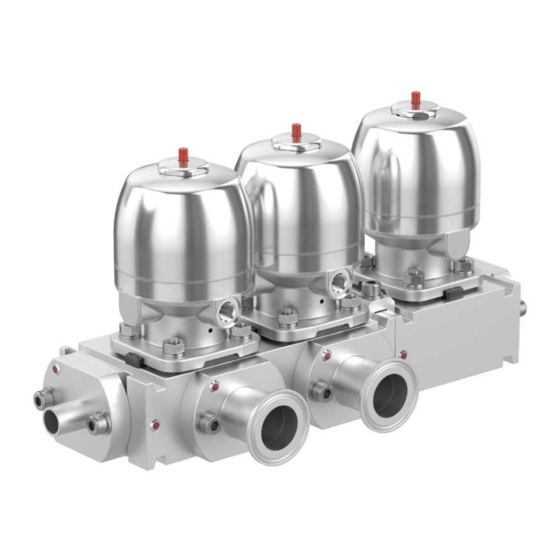
- Page 1 GEMÜ P600S M-block diaphragm valve with flexible connection system Operating instructions further information webcode: GW-P600S...
- Page 2 All rights including copyrights or industrial property rights are expressly reserved. Keep the document for future reference. © GEMÜ Gebr. Müller Apparatebau GmbH & Co. KG 27.10.2023 GEMÜ P600S 2 / 31 www.gemu-group.com...
-
Page 3: Table Of Contents
14.2 Fitting/removing spare parts ......15 Disposal .............. 16 Returns ..............17 Specification GEMÜ P600S ........18 EU Declaration of Incorporation according to the EC Machinery Directive 2006/42/EC, Annex II B ... 19 Manufacturer's declaration according to the Pres- sure Equipment Directive 2014/68/EU .... -
Page 4: General Information
Hot plant components! Working medium The medium that flows through the GEMÜ product. Diaphragm size Uniform seat size of GEMÜ diaphragm valves for different nominal sizes. 1.3 Warning notes Wherever possible, warning notes are organised according to the following scheme:... -
Page 5: Safety Information
2. Do not paint the bolts and plastic parts of the product. 3. Carry out installation and commissioning using trained The GEMÜ P600S valve block made from stainless steel com- personnel. prises one or more diaphragm valve seats. The individual 4. -
Page 6: Product Label
Item number Traceability number Consecutive number WARNING The manufacturing month is coded under the traceability number and can be requested from GEMÜ. The product was Improper use of the product manufactured in Germany. ▶ Risk of severe injury or death. -
Page 7: Order Data
Spigot DIN EN 10357 series B (2014 edition; formerly DIN 11850 series 1) Spigot EN 10357 series A/DIN 11866 series A formerly DIN 11850 series 2 Spigot DIN 11850 series 3 Spigot JIS-G 3447 www.gemu-group.com 7 / 31 GEMÜ P600S... -
Page 8: Technical Data
PTFE diaphragms exposed to high temperature fluctuations. The maintenance cycles must be adapted accordingly. GEMÜ 555 and 505 globe valves are particularly suitable for use in the area of steam generation and distribution. The following valve arrangement for interfaces between steam pipes and process pipes has proven itself over time: A globe valve for shutting off steam pipes and a diaphragm valve as an interface to the process pipes. - Page 9 O-ring EPDM FEP/FKM 6.6 Mechanical data Weight: Actuator size 2T1, 2R1 1.9 kg The mechanical data can be found in the product types' datasheets in conjunction with the technical drawing of the valve block. www.gemu-group.com 9 / 31 GEMÜ P600S...
-
Page 10: Dimensions
7 Dimensions 7 Dimensions 7.1 Actuator dimensions ØB øB 15 - 25 2T1, 2R1 137.5 38.0 53.0 90.0 G 1/4 M16x1 AG = actuator size Dimensions in mm GEMÜ P600S 10 / 31 www.gemu-group.com... -
Page 11: Body Dimensions
7 Dimensions 7.2 Body dimensions 20, 25 58.4 93.0 45.6 116.0 58.0 Dimensions in mm www.gemu-group.com 11 / 31 GEMÜ P600S... - Page 12 7 Dimensions 20, 25 58.4 93.0 59.0 116.0 58.0 Dimensions in mm GEMÜ P600S 12 / 31 www.gemu-group.com...
- Page 13 7 Dimensions 20, 25 58.4 93.0 59.0 209.0 58.0 151.0 Dimensions in mm www.gemu-group.com 13 / 31 GEMÜ P600S...
- Page 14 7 Dimensions 20, 25 58.4 93.0 59.0 302.0 58.0 151.0 244.0 Dimensions in mm GEMÜ P600S 14 / 31 www.gemu-group.com...
-
Page 15: Connection Dimensions
29.0 76.0 37.4 40.0 25.0 58.0 29.0 76.0 34.5 40.0 25.4 1.65 58.0 29.0 76.0 34.2 40.0 33.4 2.77 58.0 29.0 76.0 37.1 40.0 33.4 3.38 58.0 29.0 76.0 36.5 40.0 Dimensions in mm www.gemu-group.com 15 / 31 GEMÜ P600S... - Page 16 42.0 A1, A2 26.0 70.0 58.0 29.0 76.0 36.2 65.0 53.0 A4, A5 29.7 74.0 58.0 29.0 76.0 38.0 65.0 57.0 A6, A7 22.1 66.0 58.0 29.0 76.0 34.2 65.0 49.0 Dimensions in mm GEMÜ P600S 16 / 31 www.gemu-group.com...
- Page 17 50.5 58.0 29.0 76.0 36.2 53.0 E4, E5 29.7 50.5 58.0 29.0 76.0 38.0 53.0 E7, E8 22.1 50.5 58.0 29.0 76.0 34.2 53.0 22.1 50.5 58.0 29.0 76.0 34.2 53.0 Dimensions in mm www.gemu-group.com 17 / 31 GEMÜ P600S...
-
Page 18: Manufacturer's Information
3. Do not exceed the maximum storage temperature. ● down. 4. Do not store solvents, chemicals, acids, fuels or similar fluids in the same room as GEMÜ products and their spare CAUTION parts. Exceeding the maximum permissible pressure. ▶ Damage to the product Provide precautionary measures against exceeding the ●... -
Page 19: Installing/Removing The Connection Adapters
1. Ensure the suitability of the GEMÜ product for each re- 9.2 Installing/removing the connection adapters spective use. 2. Check the technical data of the GEMÜ product and the ma- terials. 3. Keep appropriate tools ready. 4. Ensure appropriate protective gear as specified in the plant operator's guidelines. -
Page 20: Installation With Clamp Connections
5. Use all flange holes. 6. Only use connector elements made of approved materials! 7. Tighten the bolts diagonally. Observe appropriate regulations for connections! After the installation: - Re-attach or reactivate all safety and protective devices. GEMÜ P600S 20 / 31 www.gemu-group.com... -
Page 21: Pneumatic Connections
Connector 2 Actuator size 2 control function 2 + 3 Control function Connectors 1 (NC) 2 (NO) 3 (DA) + = available / - = not available (see figure for connectors 2 / 4) www.gemu-group.com 21 / 31 GEMÜ P600S... -
Page 22: Commissioning
(water hammer). CAUTION Cleaning agent ▶ Damage to the GEMÜ product. The plant operator is responsible for selecting the clean- ● ing material and performing the procedure. 1. Check the tightness and the function of the product (close and reopen the product). -
Page 23: Troubleshooting
Valve body faulty or corroded Check valve body for potential damage, replace valve body if necessary Incorrect assembly Check the assembly of the O-ring at the interfaces of the valve bodies * see chapter "Spare parts" www.gemu-group.com 23 / 31 GEMÜ P600S... -
Page 24: Inspection And Maintenance
Check parts for by trained personnel. potential damage; replace if necessary (only use genuine Do not extend hand lever. GEMÜ shall assume no liability ● parts from GEMÜ). whatsoever for damages caused by improper handling or third-party actions. - Page 25 6. If it is difficult to screw it in, check the thread, replace damaged parts (only use genuine parts from GEMÜ). ● Place the compressor loosely on the actuator spindle, fit the recesses D into the guides C. It must be possible to 7.
-
Page 26: Disposal
10. Press the diaphragm face tightly onto the backing dia- phragm manually so that it returns to its original shape and fits closely on the backing diaphragm. GEMÜ P600S 26 / 31 www.gemu-group.com... -
Page 27: Returns
Returned goods can be processed only when this note is completed. If no return delivery note is included with the product, GEMÜ cannot process credits or repair work but will dispose of the goods at the operator's expense. -
Page 28: Specification Gemü P600S
Please do not write here! Customer: K-No.: Department: P600: Address: M600: Phone: E-mail: GEMÜ Gebr. Müller Apparatebau GmbH & Co. KG · Fritz-Müller-Str. 6-8 · 74653 Ingelfingen · Germany · Phone +49(0)7940/123-0 info@gemue.de · www.gemu-group.com GEMÜ P600S 28 / 31 www.gemu-group.com... -
Page 29: Eu Declaration Of Incorporation According To The Ec Machinery Directive 2006/42/Ec, Annex Ii B
EC Machinery Directive 2006/42/EC, Annex II B Machinery Directive introductory text We, the company GEMÜ Gebr. Müller Apparatebau GmbH & Co. KG Fritz-Müller-Strasse 6–8 74653 Ingelfingen-Criesbach, Germany hereby declare under our sole responsibility that the below-mentioned product complies with the relevant essential health and safety requirements in accordance with Annex I of the above-mentioned Directive. -
Page 30: Manufacturer's Declaration According To The Pressure Equipment Directive 2014/68/Eu
M-block diaphragm valve with flexible connection system The product has been developed and produced according to GEMÜ's in-house process instructions and standards of quality which comply with the requirements of ISO 9001 and ISO 14001. According to Article 4, Paragraph 3 of the Pressure Equipment Directive 2014/68/EU, this product must not be identified by a CE-marking. - Page 31 GEMÜ Gebr. Müller Apparatebau GmbH & Co. KG Fritz-Müller-Straße 6-8, 74653 Ingelfingen-Criesbach, Germany Subject to alteration Phone +49 (0) 7940 1230 · info@gemue.de www.gemu-group.com 10.2023 | 88887962...
Need help?
Do you have a question about the P600S and is the answer not in the manual?
Questions and answers