Table of Contents
Advertisement
Quick Links
Advertisement
Table of Contents

Related Manuals for Amazone GBK 11


Summary of Contents for Amazone GBK 11
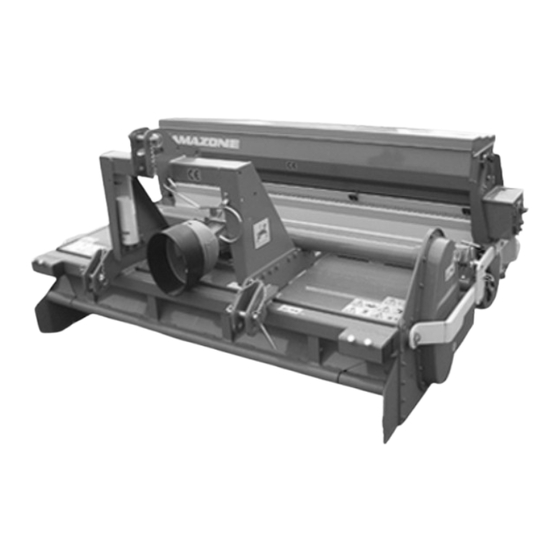
- Page 1 Operating Manual LANDSCAPING AND LANDSCAPE MAINTENANCE COMBINATIONS GBK / GNK / HR 11 - 13 - 15 - 20 - 25 Please read and follow this op- erating manual before putting MG2299 the machine into operation. BAF0004.0 01.09 Keep it in a safe place for future Printed in France use.
- Page 2 READING THE INSTRUCTION manual and adhering to it should not appear to be inconvenient and superfluous as it is not enough to hear from others and to realise that a machine is good, to buy it and to believe that now everything should work by itself.
- Page 3 Basic weight (kg): Permissible total weight Permissible total weight (kg): (kg): Maximum load (kg): Maximum load (kg): Manufacturer's address AMAZONE S.A. FORBACH 17, rue de la Verrerie BP 90106 F-57602 Forbach, France Phone: +33 (0) 3 87 84 65 70 Fax:...
- Page 4 Operator evaluation Dear Reader We update our operating manuals regularly. Your suggestions for improvement help us to create ever more user-friendly manuals. Please send your suggestions to: AMAZONE S.A. FORBACH 17, rue de la Verrerie BP 90106 F-57602 Forbach, France...
-
Page 5: Table Of Contents
Table of Contents Operator information .................. 8 Purpose of the document....................8 Locations in the operating manual ..................8 Diagrams used ........................8 General safety instructions ................ 9 Obligations and liability ....................... 9 Representation of safety symbols ..................11 Organisational measures ....................12 Safety and protection equipment.................. - Page 6 Tips on drilling in slow or fast gear..................55 7.6.1 Adjusting the gearbox in fast mode..................56 Quantity table........................57 Calibration test ........................57 Maintenance ........................59 AMAZONE GBK combination seeding system........60 Fields of application......................60 GBK combination seeding system with reciprocating power harrow ........61 8.2.1 Setting the working depth ....................61 8.2.2 Adjusting the lateral weeders.....................62...
- Page 7 Table of Contents 10.3.6 Use on heavily compacted sports courts ................77 10.3.7 Weekly maintenance of compacted soil ................77 10.3.8 Adjusting the front scarifier bar ..................77 10.3.9 Adjusting the rear brush....................78 10.4 Care of sandy artificial turf ....................78 10.5 Adjusting the brush bars ....................
-
Page 8: Operator Information
Operator information Operator information The "Operator information" section supplies information on using the operating manual. Purpose of the document This operating manual · Describes the operation and maintenance of the machine. · Provides important information on safe and efficient handling of the machine. -
Page 9: General Safety Instructions
General safety instructions General safety instructions This section contains important information on the safe operation of the machine. Obligations and liability Comply with the instructions in the operating manual Knowledge of the basic safety information and safety regulations is a basic requirement for safe handling and fault-free machine operation. - Page 10 General safety instructions Risks in handling the machine The machine has been constructed to the state-of-the art and the recognised rules of safety. However, there may be risks and restric- tions which occur when operating the machine · For the health and safety of the operator or third persons, ·...
-
Page 11: Representation Of Safety Symbols
General safety instructions Representation of safety symbols Safety instructions are indicated by the triangular safety symbol and the highlighted signal word. The signal word (DANGER, WARNING, CAUTION) describes the gravity of the risk and has the following sig- nificance: DANGER Indicates an immediate high risk, which will result in death or extremely serious physical injury (loss of body parts or long term damage) if not avoided. -
Page 12: Organisational Measures
General safety instructions Organisational measures The operator must provide the necessary personal protective equip- ment, such as: · Protective glasses · Protective shoes · Protective suit · Skin protection, etc. The operating manual · Must always be kept at the place at which the machine is oper- ated. -
Page 13: Operator Training
General safety instructions Operator training Only those people who have been trained and instructed may work with/on the machine. The operator must clearly specify the responsi- bilities of the people charged with operation, maintenance and repair work. People being trained may only work with/on the machine under the supervision of an experienced person. -
Page 14: Safety Measures In Normal Operation
General safety instructions Safety measures in normal operation Only operate the machine if all the safety and protection equipment is fully functional. Check the machine at least once a day for visible damage and check the function of the safety and protection equipment. Danger from residual energy Note that there may be residual mechanical, hydraulic, pneumatic and electrical/electronic energy from the machine. -
Page 15: 2.11. Spare And Wear Parts And Auxiliary Materials
General safety instructions 2.11. Spare and wear parts and auxiliary materials Immediately replace any machine parts which are not in a perfect state. Only use genuine spare and wear parts or the parts cleared by AMAZONEN-WERKE so that the operating permit retains its validity in accordance with national and international regula- tions. - Page 16 General safety instructions Warning symbols - structure Warning symbols indicate dangers on the machine and warn against residual dangers. At these points, there are permanent or unexpected dangers. A warning symbol consists of two fields: Field 1 is a symbol describing the danger, surrounded by triangular safety symbol.
- Page 17 General safety instructions Order number and explanation Warning symbols MD 075 Risk of fingers and hands being cut or sev- ered by rotating machine parts. This hazard can cause extremely serious injuries with the loss of body parts such as fingers or hands.
- Page 18 General safety instructions MD 082 Danger of falling from treads and platforms when riding on the machine or climbing on operating machinery. This hazard can cause extremely serious and potentially fatal injuries. Riding on the machine and/or climbing on oper- ating machinery is forbidden.
- Page 19 General safety instructions MD 097 Risk of crushing torso in the stroke range of the three-point suspension due to narrowing spaces when the three-point hydraulic sys- tem is actuated. This would cause extremely serious injuries and even death. Persons must not enter the stroke area of the three-point suspension when the three-point hydraulic system is actuated.
- Page 20 General safety instructions MD 145 The CE mark signifies that the machine complies with basic health and safety requirements. MD 150 Risk of fingers and hands being cut or sev- ered by rotating, unprotected, sharp-edged machine parts. This hazard can cause extremely serious injuries with the loss of body parts such as fingers or hands.
-
Page 21: Positioning Of Warning Symbols And Other Labels
General safety instructions 2.14.1 Positioning of warning symbols and other labels Warning symbols The following diagrams show the arrangement of the warning symbols on the machine. Stone burier GBK / GNK / HR BAF0004.0 01.09... - Page 22 General safety instructions Seed boxes GBK / GNK / HR BAF0004.0 01.09...
- Page 23 General safety instructions Reciprocating power harrow GBK / GNK / HR BAF0004.0 01.09...
- Page 24 General safety instructions Rotary harrows GBK / GNK / HR BAF0004.0 01.09...
- Page 25 General safety instructions GBK / GNK / HR BAF0004.0 01.09...
-
Page 26: Dangers If The Safety Information Is Not Observed
General safety instructions 2.15 Dangers if the safety information is not observed Nonobservance of the safety information · Can pose both a danger to people and also to the environment and machine. · Can lead to the loss of all warranty claims. Seen individually, non-compliance with the safety information could pose the following risks: ·... -
Page 27: Safety Information For The Operator
General safety instructions 2.17 Safety information for the operator WARNING Risk of being crushed, cut, caught, drawn in or struck due to insufficient traffic and operational safety. Before starting up the machine and the tractor, always check their traffic and operational safety. 2.17.1 General safety and accident prevention information ·... - Page 28 General safety instructions · Secure the operating lever of the tractor hydraulic system so that unintentional raising or lowering is impossible, before connecting the machine to or disconnecting the machine from the tractor's three-point hydraulic system. · When coupling and uncoupling machines, move the support equipment (if available) to the appropriate position (stability).
- Page 29 General safety instructions Machine transportation · When using public highways, national road traffic regulations must be observed. · Before moving off, check: the correct connection of the supply lines the lighting system for damage, function and cleanliness the brake and hydraulic system for visible damage that the parking brake is released completely the proper functioning of the braking system ·...
-
Page 30: General Safety And Accident Prevention Information
General safety and accident prevention information General safety and accident prevention information Basics: Make sure the equipment is safe to drive and operate before star- ting it up. Follow the generally applicable safety and accident-prevention regulations as well as the information in this operating manual. The attached warning and information labels attached to the machine provide important details for avoiding danger;... -
Page 31: Attached Equipment
General safety and accident prevention information 18. The load on the front axle of the tractor can vary during lifting, depending on the size of the equipment. Observe the required front axle load (20 % of the tractor weight). 19. Keep an eye on protruding parts and/or shifting weight when driving around corners. -
Page 32: Pto Shaft Operation
General safety and accident prevention information Do not stand between the tractor and the equipment when oper- ating the external controls on the three-point attachment. When transporting the implement, always allow sufficient side- ways lock for the tractor's three-point linkage. When driving on the road with the implement raised, the control lever must be locked against lowering. -
Page 33: General Safety And Accident Prevention Regulations For Maintenance, Servicing And Care
General safety and accident prevention information 14. Caution - danger from flywheel run-on when the universal joint shaft is switched off. Do not approach the implement during this time. Only work on it after it is at a standstill. 15. Carry out cleaning, lubrication or adjustment of universal joint shaft driven implements or the PTO shaft only with the universal joint shaft switched off, the engine switched off and the ignition key removed. -
Page 34: Machine Data
Intended use also includes compliance with instructions specified by the manufacturer concerning operation, servicing and maintenance as well as the exclusive use of genuine AMAZONE spare parts. The Amazone grass seeder combination may only be used, serviced and maintained by persons who are familiar with the machine and who have received instruction concerning the risks involved. -
Page 35: Implements For Soil Tillage
Implements for soil tillage Implements for soil tillage The AMAZONE GBK, GNK and HR landscaping and landscape main- tenance combinations consist of: · a soil tillage implement, · a screen roller or a smooth roller, · a seed box for grass seed (re)sowing. - Page 36 Implements for soil tillage Scraper bars The combination of a scarifier at the front and a scraper bar behind can be used to level hard sports courts. Scraper bars front and rear are ideal for incorporating sand into synthetic turf. Reciprocating harrow Supporting bars Spring steel tine bars...
-
Page 37: Installing And Adjusting The Reciprocating Power Harrow
Implements for soil tillage 5.1.3 Installing and adjusting the reciprocating power harrow The distance between the PTO shaft and the pivot points of the lower links will usually be different with different tractor types. Optional ex- tension pieces are available for the lower headstock so the reciprocat- ing power harrow harrow can be fitted to any tractor type. -
Page 38: Adjusting The Pto Shaft The First Time The Machine Is Coupled
Implements for soil tillage 5.1.6 Adjusting the PTO shaft the first time the machine is coupled Adjust the PTO shaft to the tractor the first time it is coupled. As this adjustment is only intended for one kind of tractor, check whether the PTO shaft needs to be modified for a different trac- tor when you install it. -
Page 39: Input Speed For The Reciprocating Power Harrow Gearbox
Implements for soil tillage 5.1.7 Input speed for the reciprocating power harrow gearbox The maximum permissible input speed for the gearbox is 540 rpm. N = 540 rpm Damage caused using speeds above 540 rpm is not covered by the guarantee. - Page 40 Implements for soil tillage GBK / GNK / HR BAF0004.0 01.09...
-
Page 41: Rotary Harrow
Implements for soil tillage Rotary harrow 5.2.1 Technical data - rotary harrow (basic machine) F61-110 F61-130 F61-150 F61-200 F61-250 Working width 1.10 1.30 1.50 2.00 2.50 Weight of basic machine (kg) Tractor power from 20 from 25 from 30 from 45 from 60 (HP) 5.2.2... -
Page 42: Pto Shaft
Implements for soil tillage The lower links on the tractor should be connected to the lower link arms on the rotary harrow and secured with cotter pins. The top link on the tractor should be adjusted so that the rotary harrow tilts slightly backwards. -
Page 43: Input Speed For The Rotary Harrow
Implements for soil tillage 5.2.6 Input speed for the rotary harrow The maximum permissible input speed for the gearbox is 540 rpm. N = 540 rpm Damage caused using speeds above 540 rpm is not covered by the guarantee. 5.2.7 Lubrication After the first 50 hours of operation, replace the oil in the reduction gears. -
Page 44: Maintenance
Implements for soil tillage 5.2.8 Maintenance Daily tasks to guarantee the functional efficiency of the machine: · Make sure that the lower links on the tractor cannot dangle to the side. · Check the tightness of all bolts, especially the mounting bolts on the central tine bracket. -
Page 45: Stone Burier
Implements for soil tillage Stone burier 5.3.1 Technical data - stone burier (basic machine) G15-85 G15-105 G25-110 G25-130 G25-150 Working width 0.85 1.05 1.10 1.30 1.50 Weight - basic machine (kg) Tractor power from 20 from 25 from 25 from 30 from 35 (PS) (ruggedised... -
Page 46: Attaching The Pto Shaft
Implements for soil tillage 5.3.4 Attaching the PTO shaft First clean the shaft in the housing and always install a greased- lubricated PTO shaft on the input shaft. 5.3.5 Adjusting the PTO shaft the first time the machine is coupled Adjust the PTO shaft to the tractor the first time it is coupled. -
Page 47: Screen Roller And Smooth Roller
Screen roller and smooth roller Screen roller and smooth roller Technical data - screen roller GIW 11 GIW 13 GIW 15 GIW 20 GIW 25 Diameter (mm) 1.10 1.30 1.50 2.00 2.50 Working width (m) (nominal width) (1.20) (1.40) (1.60) (2.10) (2.60) Weight (kg) -
Page 48: Uncoupling The Screen Roller
Screen roller and smooth roller Uncoupling the screen roller The screen roller is attached to the soil tillage implement by two carry- ing arms (Fig. 6.4-1/1). Proceed as follows to separate it from the implement: · Attach the machine to the tractor. ·... -
Page 49: Water Connection On Smooth Roller
Screen roller and smooth roller C A U T I O N The screen roller must be secured before it is uncoupled, to stop it tipping over. To attach a different implement, uncouple the reciprocating power harrow from the roller as follows: ·... -
Page 50: Maintenance
Screen roller and smooth roller Maintenance The flange bearing should be lubricated every 50 hours of operation (Fig. 6.6). GBK / GNK / HR BAF0004.0 01.09... -
Page 51: Seed Box
Seed box Seed box Technical data Seed box 1.10 m 1.30 m 1.50 m 2.00 m 2.50 m Working width (m) 1.10 1.30 1.50 2.00 2.50 Total width (m) 2.84 1.44 1.64 1.84 2.34 Height (m) 0.51 0.51 0.51 0.51 0.51 Length (m) 0.43... -
Page 52: Filling The Seed Box
Seed box The chain drive is covered by a split chain guard. Procedure for removing the seed box: · Remove the upper and lower parts of the chain guard on the chain drive (Fig. 7.2-2). · Use pliers to release the spring on the pulley. ·... -
Page 53: Emptying The Seed Box
Seed box Emptying the seed box The seed box is emptied as follows: · Undo the thumb bolts holding the emptying rail. · Release the rail at the rear of the seed box (Fig. 7.4-1). · Attach a sack to the hook on the rails. ·... -
Page 54: Setting The Sowing Rate
Seed box Setting the sowing rate Use the quantity table in section 7.7 to set the rate. · To set the sowing rate, screw the handle onto the gear lever (Fig. 7.5/1). · Set the pointer to the value selected from the quantity table. ·... -
Page 55: Tips On Drilling In Slow Or Fast Gear
Seed box Tips on drilling in slow or fast gear The gear of the sowing shaft, and therefore the sowing rate, can be set using the gearbox (Fig. 7.6/2). There is also a speed converter in the gearbox. Two gears can be set by turning a gear wheel: slow fast (see Fig. -
Page 56: Adjusting The Gearbox In Fast Mode
Seed box 7.6.1 Adjusting the gearbox in fast mode To set the gearbox to fast mode, open the cover on the side of the gearbox (Fig. 7.6.1/1) by undoing the thumb bolts and both thumb nuts (Fig. 7.6.1/2). Take the lower gear wheel (Fig. 7.6.1/3) off the shaft, reverse it and replace it on the shaft. -
Page 57: Quantity Table
Seed box Quantity table Seed: Resilient grass Specific weight: 0.37 kg/L Gear setting Sowing rate in kg/ha in selected gear Slow Fast 25 kg/ha 38 kg/ha 56 kg/ha 137 kg/ha 82 kg/ha 212 kg/ha 109 kg/ha 304 kg/ha 137 kg/ha 387 kg/ha 163 kg/ha 464 kg/ha... - Page 58 Seed box · Turn the roller until seed emerges from the seed wheels. · Use the rail to empty the chute into the container and then push the rail back towards the chute. The calibration test can now start. Number of rotations of the roller corresponding to a worked area of one "are"...
-
Page 59: Maintenance
Seed box Maintenance The AMAZONE seed box is designed to require minimal mainte- nance. However, we recommend checking the following points at regular intervals: Visual check of the oil level in the gearbox using the oil-level indicator. It is not necessary to change the oil. To top up the oil, remove the cover plate on the box by undoing the M8 screw in the centre of the plate. -
Page 60: Amazone Gbk Combination Seeding System
AMAZONE GBK combination seeding system AMAZONE GBK combination seeding system Fields of application With the AMAZONE GBK combination seeding system you can create your greens, such as e.g. sports fields, fairways, parks, etc… Depending on the chosen soil tillage implement, in one working session, it is possible to: ·... -
Page 61: Gbk Combination Seeding System With Reciprocating Power Harrow
AMAZONE GBK combination seeding system GBK combination seeding system with reciprocating power harrow 8.2.1 Setting the working depth The reciprocating power harrow must be supported continuously by the roller when working to guarantee a uniform working depth. The depth is set by the top cams of the support (Fig. 8.2.1-1). -
Page 62: Adjusting The Lateral Weeders
AMAZONE GBK combination seeding system The lower cams allow you to lock the carrying arms and so transfer the weight of the roller to the reciprocating power harrow. That way, the teeth of the reciprocating power harrow can better penetrate hard soil. -
Page 63: Adjusting The Chute
AMAZONE GBK combination seeding system The lateral weeders should never penetrate the soil while the machine is in operation, otherwise they would create a small groove. 8.2.3 Adjusting the chute The chute allows you to distribute the seed evenly, directing it to the ground and stopping it drifting in the wind. -
Page 64: Levelling Blade
AMAZONE GBK combination seeding system 8.2.4 Levelling blade The reciprocating power harrow can be fitted with an optional levelling blade for better forming of the surface. The levelling blade is adjusted as follows: · Undo the securing pin on each crank (Fig. 8.2.4-1). -
Page 65: Gbk Combination Seeding System With Rotary Harrow
AMAZONE GBK combination seeding system GBK combination seeding system with rotary harrow 8.3.1 Setting the working depth The working depth of the rotary harrow is set using the side supports. To adjust the working depth, insert the locking pin into the desired hole and secure it there (Fig. -
Page 66: Gbk Combination Seeding System With Stone Burier
AMAZONE GBK combination seeding system GBK combination seeding system with stone burier 8.4.1 Commissioning The stone burier is designed to break up soil, plant residue and small stones on the surface and incorporate them into the soil. For problem- free operation, make sure the diameter of the stones does not exceed approx. -
Page 67: Setting The Working Depth
AMAZONE GBK combination seeding system · Remove the harrow sieve completely (Fig. 8.4.1-2). · Remove the knife in which the object is blocked. · Remove the object. 8.4.2 Setting the working depth The working depth of the stone burier is set using the side supports. -
Page 68: Driving
AMAZONE GBK combination seeding system 8.4.3 Driving In order to achieve a good result, the machine must be free to follow the soil contour. For this, the three-point hydraulic system on the trac- tor must be in the lowest position and able to move freely. -
Page 69: Amazone Gnk Overseeder
Before resowing lawn, we recommend cutting the grass very short (2 to 3 cm) and, if necessary, scarifying with an AMAZONE Grasshopper or Profihopper, and removing the scarified material. If you do not have this equipment, you can scarify with the scarifying harrow without simultaneous sowing and gathering up the material, and later gather up the scarified material before actually reseeding. -
Page 70: Adjusting The Chute
AMAZONE GNK Overseeder 9.2.2 Adjusting the chute The chute allows you to distribute the seed evenly, directing it to the ground and stopping it drifting in the wind. Change the angle of the chute to set the sowing depth and/or and dispensing point so the seed makes optimal contact with the rough- ened surface and the loose soil. - Page 71 AMAZONE GNK Overseeder GBK / GNK / HR BAF0004.0 01.09...
-
Page 72: Amazone Hr Hard Court Reconditioner
45 10.2 Fields of application The AMAZONE HR hard sports court reconditioner consists of a re- ciprocating power harrow and a smooth roller fitted with a lateral and rear brush. The HR can be configured for the following work by changing the different tine bars: ·... - Page 73 AMAZONE HR hard court reconditioner Adjusting the top cams: · Raise the machine until the top cams no longer touch the carrying arms. · Use the crank to undo the securing bolts on the cams (Fig. 10.3.2-2). · Turn the cams to set the working depth. Make sure that the setting is the same on both sides of the machine.
-
Page 74: Adjusting The Lateral Weeders
AMAZONE HR hard court reconditioner · Undo the securing bolts on the lower cams. · Adjust the lower cams until they touch the carrying arms (Fig. 10.3.2-3), · Retighten the securing bolts. 10.3.3 Adjusting the lateral weeders After the working depth has been set, you need to bring the lateral weeders on the side ends of the front tine bars to the working depth. -
Page 75: Adjusting The Lateral Brushes
AMAZONE HR hard court reconditioner 10.3.4 Adjusting the lateral brushes The two lateral brushes level the soil between the tracks. In their working position, the lateral brushes should be about 1 cm above the ground in order to achieve the best result. -
Page 76: Adjusting The Rear Brush
AMAZONE HR hard court reconditioner 10.3.5 Adjusting the rear brush The surface is smoothed again with the rear brush. The scraper is pressed down under its own weight, so no further ad- justment is needed. The brush is merely lowered. -
Page 77: Use On Heavily Compacted Sports Courts
AMAZONE HR hard court reconditioner 10.3.6 Use on heavily compacted sports courts To loosen compacted soils, the carrying arms must be locked using the cams, so the weight of the roller is placed on the reciprocating power harrow (see section 8.2.1). -
Page 78: Adjusting The Rear Brush
AMAZONE HR hard court reconditioner 10.3.9 Adjusting the rear brush The scraper bar, attached on the back of the reciprocating power harrow for weekly maintenance of tamped areas, levels the surface worked by the tines of the scarifier. The bar must be set so that the brushes touch the surface in their operating position. - Page 79 AMAZONE HR hard court reconditioner NOTES ......................................................................................................................................................................................................................................................................................................................................................................................................................................................................................................................................................................................................................................................................................................................................................................................................................................................................................................................................................................................................................................................................................................
-
Page 80: Gbk / Gnk / Hr Baf0004.0
AMAZONE HR hard court reconditioner H. DREYER GmbH & Co. KG Postfach 51 Phone: +49 5405 501-0 D-49202 Hasbergen-Gaste Fax: +49 5405 501-234 Germany e-mail: amazone@amazone.de http:// www.amazone.de az S.A. FORBACH 17, rue de la Verrerie – BP 90106 Tel.:...
Need help?
Do you have a question about the GBK 11 and is the answer not in the manual?
Questions and answers