Table of Contents
Advertisement
Advertisement
Table of Contents

Related Manuals for Amazone Grasshopper SmartCut


Summary of Contents for Amazone Grasshopper SmartCut
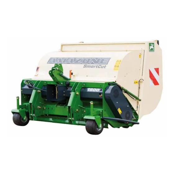
- Page 1 Operating manual Grasshopper HorseHopper SmartCut SmartCut GH 1800 SUPER HH 1800 SUPER GH 2100 SUPER HH 2100 SUPER Please read and follow this op- erating manual before putting MG5084 the machine into operation. BAF0009.3 05.17 Keep it in a safe place for future Printed in France use.
- Page 2 READING THE INSTRUCTION manual and adhering to it should not appear to be inconvenient and superfluous as it is not enough to hear from others and to realise that a machine is good, to buy it and to believe that now everything should work by itself.
- Page 3 +33 (0) 3 87 84 65 71 E-mail: forbach@amazone.fr Spare part orders Spare parts lists are freely accessible in the spare parts portal at www.amazone.de. Please send orders to your AMAZONE dealer. Formalities of the operating manual Document number: MG5084 Compilation date: 05.17 ...
- Page 4 User evaluation Dear Reader We update our operating manuals regularly. Your suggestions for improvement help us to create ever more user-friendly manuals. Please send your suggestions to: AMAZONE S.A. FORBACH 17, rue de la Verrerie BP 90106 F-57602 Forbach, France...
-
Page 5: Table Of Contents
User information User information ..................7 Purpose of the document ......................7 Locations in the operating manual ................... 7 Diagrams used ......................... 7 General safety instructions ................. 8 Obligations and liability ......................8 Representation of safety symbols ..................10 Organisational measures ....................... 11 Safety and protection equipment ................... - Page 6 User information The mower unit ..................38 Fitting the mowing and scarifying tools ................. 38 Mowing ..........................43 Scarifying ..........................44 Mulching ..........................46 Collecting ..........................46 Emptying the hopper ......................46 Adjusting the cutting height ..............48 Front roller (option) ........................ 50 Cleaning the machine ................
-
Page 7: User Information
User information User information The "User information" section supplies information on using the op- erating manual. Purpose of the document This operating manual • Describes the operation and maintenance of the machine. • Provides important information on safe and efficient handling of the machine. -
Page 8: General Safety Instructions
General safety instructions General safety instructions This section contains important information on safe operation of the machine. Obligations and liability Comply with the instructions in the operating manual Knowledge of the basic safety information and safety regulations is a basic requirement for safe handling and fault-free machine operation. Obligations of the operator The operator is obliged only to let those people work with/on the ma- chine who... - Page 9 General safety instructions Risks in handling the machine The machine has been constructed to the state-of-the art and the recognised rules of safety. However, there may be risks and re- strictions which occur when operating the machine • For the health and safety of the user or third persons, •...
-
Page 10: Representation Of Safety Symbols
General safety instructions Representation of safety symbols Safety instructions are indicated by the triangular safety symbol and the highlighted signal word. The signal word (DANGER, WARNING, CAUTION) describes the gravity of the risk and has the following sig- nificance: DANGER Indicates an immediate high risk, which will result in death or extremely serious physical injury (loss of body parts or long term damage) if not avoided. -
Page 11: Organisational Measures
General safety instructions Organisational measures The operator must provide the necessary personal protective equip- ment, such as: • Protective glasses • Protective shoes • Protective suit • Skin protection, etc. The operation manual • Must always be kept at the place at which the machine is oper- ated. -
Page 12: User Training
General safety instructions User training Only those people who have been trained and instructed may work with/on the machine. The operator must clearly specify the responsi- bilities of the people charged with operation, maintenance and repair work. People being trained may only work with/on the machine under the supervision of an experienced person. -
Page 13: Safety Measures In Normal Operation
2.10 Constructive changes You may not make changes, expansions or conversions to the ma- chine without the authorisation of AMAZONE. This is also valid when welding support parts. Any expansion or modification work shall require the written approval of AMAZONE. Only use the modification and accessory parts re- leased by AMAZONE so that the operating permit, for example, re- mains valid in accordance with national and international regulations. -
Page 14: Spare And Wear Parts And Aids
Immediately replace any machine parts which are not in a perfect state. Use only genuine AMAZONE spare and wear parts or the parts cleared by AMAZONE so that the operating permit retains its validity in accordance with national and international regulations. If you use... -
Page 15: Warning Symbols And Other Signs On The Machine
General safety instructions 2.13 Warning symbols and other signs on the machine Always keep all the warning symbols of the machine clean and in a legible state. Replace illegible warning symbols. You can obtain the warning symbols from your dealer using the order number (e.g. MD 075). - Page 16 General safety instructions Order number and explanation Warning symbols MD 075 Risk of fingers and hands being cut or sev- ered by rotating machine parts. This hazard can cause extremely serious injuries with the loss of body parts such as fingers or hands.
- Page 17 General safety instructions MD 087 Risk of toes or feet being cut or severed by power-driven tools. This hazard can cause serious injuries, including loss of parts of the body from toes or feet. Maintain a sufficient safety distance from the danger area while the tractor engine is running and the PTO shaft/hydraulic system is connect- MD 095...
- Page 18 General safety instructions MD 097 Risk of any part of the body being crushed due to standing in the stroke area of the three-point suspension when the three-point hydraulics are operated. This hazard can cause extremely serious and potentially fatal injuries. •...
- Page 19 General safety instructions MD 113 Study and observe the instructions for cleaning, servicing and maintaining in the appropriate chapter of the operating manual. MD 114 This symbol indicates a lubrication point MD 115 The maximum operating pressure of the hydrau- lic system is 200 bar.
- Page 20 General safety instructions MD 170 Risk of being crushed, drawn in or caught by unprotected, moving machine parts as a re- sult of missing safety devices. This hazard can cause extremely serious inju- ries, including the loss of body parts. Close protective equipment which has been opened or refit protective equipment which has been removed before you start the machine.
-
Page 21: Positioning Of Warning Symbols And Other Labels
General safety instructions 2.13.1 Positioning of warning symbols and other labels Warning symbols The following diagrams show the arrangement of the warning symbols on the machine. MD078 MD123 MD100 MD100 MD078 MD097 MD087 MD079 MD075 MD118 MD078 MD076 MD078 MD075 GH HH Super SMARTCUT BAF0009.3 05.17... -
Page 22: Dangers If The Safety Information Is Not Observed
General safety instructions 2.14 Dangers if the safety information is not observed Non-observance of the safety information • Can pose both a danger to people and also to the environment and machine. • Can lead to the loss of all warranty claims. Seen individually, non-compliance with the safety information could pose the following risks: •... -
Page 23: Safety Information For Users
General safety instructions 2.16 Safety information for users WARNING Risk of being crushed, cut, caught, drawn in or struck due to insufficient traffic and operational safety! Before starting up the machine and the tractor, always check their traffic and operational safety. 2.16.1 General safety and accident prevention information •... - Page 24 General safety instructions • Secure the operating lever of the tractor hydraulic system so that unintentional raising or lowering is impossible, before connecting the machine to or disconnecting the machine from the tractor's three-point hydraulic system. • When coupling and uncoupling machines, move the support equipment (if available) to the appropriate position (stability).
- Page 25 General safety instructions ο Remove the ignition key Machine transportation • When using public highways, national road traffic regulations must be observed. • Before moving off, check: ο the correct connection of the supply lines ο the lighting system for damage, function and cleanliness ο...
-
Page 26: Hydraulic System
General safety instructions braking (lock the pedals). 2.16.2 Hydraulic system • The hydraulic system is under a high pressure. • Ensure that the hydraulic hose lines are connected correctly. • When connecting the hydraulic hose lines, ensure that the hy- draulic system is unpressurised on both the machine and tractor sides. -
Page 27: Electrical System
General safety instructions 2.16.3 Electrical system • When working on the electrical system, always disconnect the battery (negative terminal). • Only use the prescribed fuses. If fuses are used with too high a rating, the electrical system will be destroyed – danger of fire. •... -
Page 28: General Description Of The Machine
General description of the machine General description of the machine Areas of application Groundkeeper / HorseHopper is intended to be used for grass cutting and scarifying in public parks as well as sports fields and gardens, etc. It can be used to collect and chop foliage in the autumn. Declaration of conformity The Groundkeeper complies with the requirements of the EC Machin- ery Directives 2006/42/EC and associated additional guidelines. -
Page 29: Technical Data
LpA = 98 dB(A). Measurements were taken under working conditions close to the driver's ear. Maximum noise emission : LwA = 115 dB(A). Intended use The AMAZONE Groundkeeper / / HorseHopper has been designed for conventional use in maintaining grassed open areas and parks (intended use). -
Page 30: Taking Delivery Of The Machine
Taking delivery of the machine Taking delivery of the machine On receiving the machine, check to see if it was damaged during transport or if parts are missing. Replacements will only be made if claims are submitted promptly to the haulage company. Please check that all the parts listed on the despatch note have been delivered. - Page 31 Attaching and removing the machine at the tractor's rear three- point linkage In order to guarantee that the machine is attached to and detached from the tractor safely, it is recommended that the procedure be car- ried out in the following sequence: •...
-
Page 32: Pto Shaft
Attaching and removing the machine at the tractor's rear three- point linkage PTO shaft Only use the PTO shaft specified by the manufacturer: • Walterscheid W 2300 with or without freewheel for tractors with max. 40 HP output • Walterscheid W 2400 with or without freewheel for tractors with outputs higher than 40 HP If you have a tractor without a double clutch for the universal joint shaft drive, you must necessarily use a freewheel PTO... -
Page 33: Fitting And Adjusting The Pto Shaft
Attaching and removing the machine at the tractor's rear three- point linkage Fitting and adjusting the PTO shaft 5.2.1 Fitting the PTO shaft Before fitting, clean the gearbox input shaft on the machine and always use grease to push the PTO shaft onto the input shaft. 5.2.2 Adjusting the PTO shaft when first attached When first attached, adjust the PTO shaft to the tractor accord-... -
Page 34: Groundkeeper / Horsehopper Transmission Input Speed
Attaching and removing the machine at the tractor's rear three- point linkage The angle defining the maximum joint bends in a universal joint on the PTO shaft can be found in the accompanying operating manual provided by the manufacturer. This manual also contains information on fitting and mainte- nance that must be observed. -
Page 35: Hydraulic Connections
Attaching and removing the machine at the tractor's rear three- point linkage Hydraulic connections • All hydraulic hose lines are equipped with grips. Coloured markings with a code number or code letter have been applied to the gripping sections in order to assign the respective hydraulic function to the pressure line of a tractor control unit! Films are stuck on the implement for the markings that illustrate the respective hydraulic function. -
Page 36: Coupling Hydraulic Hose Lines
Attaching and removing the machine at the tractor's rear three- point linkage WARNING Risk of infection from hydraulic fluid escaping at high pressure. When coupling/uncoupling the hydraulic hose line, ensure that the hydraulic system is not under pressure on the tractor or machine side. If you are injured by hydraulic fluid, contact a doctor immediately. -
Page 37: Disconnecting Hydraulic Hose Lines
Attaching and removing the machine at the tractor's rear three- point linkage 5.4.2 Disconnecting hydraulic hose lines 1. Swivel the actuation lever on the tractor control unit on the trac- tor to float position (neutral position). 2. Unlock the hydraulic connectors from the hydraulic sockets. 3. -
Page 38: The Mower Unit
The mower unit The mower unit The Groundkeeper / HorseHopper Super has a flail-type mower unit. This involves free-moving cutting tools which are suspended on a large-diameter tube. When the rotor starts to turn, the cutting and scarifying blades are erected by centrifugal force, which allows them to reach into the grass which is to be cut and mow it off. - Page 39 The mower unit 50 % 100 % 100 % 50 % 100 % 100 % Mowing Scarifying Scarifying Wing blade, Wing blade, Wing blade, blade blade blade long, H77 long, H77 long, H60 ground ground ground (2 mm) (3 mm) sharpened Piece Piece...
- Page 40 The mower unit Wear limit of suspended tools: The blade fasteners and clip bolts must be checked regularly for wear. Heavily worn tools must be promptly replaced. Figs. 8.1-2 and 8.1-3 show the limits of wear for the mounting brackets. used used CAUTION...
- Page 41 The mower unit Blade overview 50 % mowing 100 % wing 100 % mowing 100 % 100 % Blade replacement 50 % wing blade, H60 and scarifying 100 % scarifying without tools blade, long, H77 mowing blade scarifying blade blade blade Mowing and collecting dry conditions...
- Page 42 The mower unit The rotor is accessed in the following manner: • Attach the machine to a tractor. • Open container to max. position, • Turn off the tractor engine. • Hang in retaining hook (Fig. 6.1-5) • Remove the screws for the intermediate hood (Fig. 6.1-6), fold up and engage with retaining hook (Fig.
-
Page 43: Mowing
The mower unit Caution: When you intend to work on the rotor with the hopper raised, make sure that the rotor is stationary and engage the retaining hook on the container. Mowing The cutting tools described above are used for mowing or scarifying. The working speed depends on the density and wetness of the turf. -
Page 44: Scarifying
The mower unit Scarifying Scarifying is usually carried out at the start or end of the vegetation period. It is possible to clean and aerate turf containing thatch and moss by simultaneously mowing, scarifying and collecting in one operation. To achieve this, straight scarifying blades are fitted between the pairs of curved mowing blades. - Page 45 The mower unit GH 2100 • Narrow scarifying, blade spacing 17 mm Scarifying blades must be attached to all clip bolts on the rotor. This type of scarifying is relatively aggressive and is suitable for restorative work on heavily thatched turf (moss) in the spring. CAUTION 1.
-
Page 46: Mulching
The mower unit Mulching If the mowing material is only to be mowed down, pulverised and then deposited immediately, the machine can be driven with the container open. (Fig. 6.4) The intermediate hood must be closed and screwed tight during this operation. - Page 47 The mower unit Never unload on a side embankment. CAUTION: Always drive with great care if the hopper is open. The closing procedure for the hopper should take at least 8 seconds. This closing speed can be adjusted via the integrated check valve (Fig.
-
Page 48: Adjusting The Cutting Height
Adjusting the cutting height Adjusting the cutting height The cutting height of the Groundkeeper / HorseHopper Super can be adjusted via the front guide wheels and rear cage roller. The height of the guide wheels is adjusted by removing and reposi- tioning the distance sleeves (fig. - Page 49 Adjusting the cutting height • Select the required working height via the height-adjusting screw (Fig. 7-3) • Tighten the clamping screw (Fig. 7-2) Care must be taken to ensure that the cage roller is equally adjusted on both sides. For this purpose, a check scale has been fitted (Fig. 7- GH HH Super SMARTCUT BAF0009.3 05.17...
-
Page 50: Front Roller (Option)
Adjusting the cutting height Front roller (option) A front roller is available as a special accessory for scarifying on une- ven terrain. It is fitted into the holders of the front guide wheels (fig. 7.1-1). To adjust the height of the machine it must be raised and the lynch pin and bolt on both sides removed. -
Page 51: Cleaning The Machine
Cleaning the machine Cleaning the machine The machine can, on occasion, become heavily soiled, especially when mowing and scarifying wet grass which is also sometimes inter- spersed with earth. In such cases, it is recommended to clean the rotor and the hopper intensively with a jet of water. The rotor and hood can be accessed as follows: •... -
Page 52: Maintenance Are Care
Maintenance are care Maintenance are care The Groundkeeper was designed to be largely maintenance free. However, the following points must be observed. Oil level in the angular gearbox The angular gearbox on the machine does not require lubrication servicing. However, the oil level must be checked at least once a year. -
Page 53: Lubrication Points
Maintenance are care Lubrication points Depending on the intensity of work, the following areas should be regularly lubricated with multipurpose grease: • Guide wheel fork bearing (fig. 9.2-1). • Rotor bearings (the V-belt protection on the left-hand side of the machine must be removed beforehand (WAF 13) (Fig. - Page 54 Maintenance are care GH HH Super SMARTCUT BAF0009.3 05.17...
-
Page 55: Extended Periods Of Downtime
Maintenance are care Extended periods of downtime If the machine is not to be used for a long period of time, it is recom- mended that, before storing, the machine is cleaned and sprayed with a suitable preservative. Before recommissioning, an authorised gar- age should check that the overload clutch between the angular gear- box and the belt drive is operating correctly. - Page 56 H. DREYER GmbH & Co. KG Postfach 51 Phone: +49 5405 501-0 D-49202 Hasbergen-Gaste e-mail: amazone@amazone.de Germany http:// www.amazone.de az S.A. FORBACH 17, rue de la Verrerie – BP 90106 Tel.: + 33 (0)3 87 84 65 70 F-57602 FORBACH Cedex...
Need help?
Do you have a question about the Grasshopper SmartCut and is the answer not in the manual?
Questions and answers