Amazone GreenDrill GD200-E Operating Manual
Catch crop seed drill
Hide thumbs
Also See for GreenDrill GD200-E:
- Operating manual (118 pages) ,
- Operating manual (106 pages)
Table of Contents

Related Manuals for Amazone GreenDrill GD200-E


Summary of Contents for Amazone GreenDrill GD200-E
- Page 1 Operating Manual Catch crop seed drill GreenDrill GD200-E / GD200-H GreenDrill GD500-H / GD500-D Please read this operating manual before initial operation. MG6863 Keep it in a safe place for future use! BAH0108-0 03.20...
- Page 3 49 (0) 5405 501-0 E-mail: amazone@amazone.de Spare Parts Order Spare parts lists are freely accessible in the spare parts portal at www.amazone.de. Please send orders to your AMAZONE dealer. Formalities of the operating manual Type: ---------------------------------- GreenDrill Document number: ---------------- MG6863 Compilation date: ------------------ 03.20...
-
Page 4: Table Of Contents
Product description .................. 24 Proper use ..........................25 3.1.1 Approved AMAZONE carrying implements ................25 Technical data ........................26 Rating plate and CE mark ..................... 26 EC Declaration of Incorporation .................... 27 ... - Page 5 Replacing the seeding shaft ....................44 Seeding with Flex seed metering wheels ................45 Fill level monitoring ........................ 46 Fill the seed hopper ....................... 46 Preparing the implement for calibration or for emptying the seed hopper ......47 ...
- Page 6 Basic settings by your AMAZONE service partner ........ 86 Opening the "Basic setting" program ..................86 7.1.1 Fan drive ..........................87 7.1.2 Seeding shaft signal tone ...................... 87 7.1.3 Implement wheel sensor ....................... 87 ...
-
Page 7: User Information
User information User information The User information section provides information concerning the operating manual. This operating manual is valid for all versions of the implement. Figures serve as a reference and are to be understood as representations of the principle. All of the equipment is described without indicating it as special equipment. -
Page 8: General Safety Instructions
General Safety Instructions General Safety Instructions This section contains supplementary information on the safety advice in the operating manual to ensure safe operation of the implement. Obligations and liability Comply with the instructions in the operating manual Knowledge of the basic safety information and safety regulations is a basic requirement for safe handling and fault-free implement operation. - Page 9 General Safety Instructions Risks in handling the implement The implement has been constructed to the state-of-the art and the recognised rules of safety. However, operating the implement may cause risks and restrictions the health and safety of the user or third persons ...
-
Page 10: Representation Of Safety Symbols
General Safety Instructions Representation of safety symbols Safety instructions are indicated by the triangular safety symbol and the highlighted signal word. The signal word (DANGER, WARNING, CAUTION) describes the severity of the risk, and carries the following meaning: DANGER Indicates an immediate hazard with high risk, which will result in death or serious bodily harm (loss of limbs or long-term harm), if it is not avoided. -
Page 11: Organisational Measures
General Safety Instructions Organisational measures The operator must provide the necessary personal protective equipment as per the information provided by the manufacturer of the crop protection agent to be used, such as: Safety glasses Protective shoes Chemical-resistant overalls ... -
Page 12: User Training
General Safety Instructions User training Only those people who have been trained and instructed may work with/on the implement. The operator must clearly specify the responsibilities of the people charged with operation and maintenance work. People being trained may only work with/on the implement under the supervision of an experienced person. -
Page 13: Safety Measures In Normal Operation
General Safety Instructions Safety measures in normal operation Only operate the implement if all the safety and protection equipment is fully functional. Check the implement at least once a day for visible damage and check the function of the safety and protection equipment. -
Page 14: Design Changes
Immediately replace any implement parts which are not in a perfect state. Use only original AMAZONE spare and wear parts or the parts cleared by AMAZONEN-WERKE so that the operating permit retains its validity in accordance with national and international regulations. If you use wear and spare parts from third parties, there is no guarantee that they have been designed and manufactured in such a way as to meet the requirements placed on them. -
Page 15: Warning Symbols On The Implement
Warning symbols on the implement Always keep all the warning symbols of the implement clean and in a legible state! Replace illegible warning symbols. You can request the warning symbols from your AMAZONE dealer using the order number (e.g., MD 075). Structure Warning symbols indicate danger areas on the implement and warn against residual dangers. - Page 16 General Safety Instructions MD 076 Risk of hands or arms being caught or drawn into the implement due to moving force transmission parts. This hazard can cause extremely serious injuries resulting in the loss of limbs. Never open or remove protective equipment, ...
- Page 17 General Safety Instructions MD 082 Risk of falling when riding the implement on treads or platforms. Causes serious, potentially fatal injuries anywhere on the body. It is forbidden to ride on the implement or climb the implement when it is running. This prohibition also applies to implements with step surfaces or platforms.
-
Page 18: Position Of Warning Symbols
General Safety Instructions MD 102 Danger from intervention in the implement, e.g. installation, adjusting, troubleshooting, cleaning, maintaining and repairing, due to the tractor and the implement being started unintentionally and rolling away. These dangers can cause extremely serious and potentially fatal injuries. ... -
Page 19: Safety Information For Users
General Safety Instructions 2.14 Safety information for users Switch off control terminal before road transport. before adjustment, maintenance and repair work. Risk of accident due to unintentional starting up of the metering unit or other implement components. 2.14.1 General safety instructions and accident prevention instructions ... - Page 20 General Safety Instructions Use of the implement Before starting work, make sure that you understand all the equipment and control elements of the implement and their functions. It is too late for this when the implement is already in operation.
-
Page 21: Hydraulic System
Have the hydraulic hose lines checked for proper functioning by a specialist at least once a year. Replace the hydraulic hose lines if they are damaged or worn. Use only original AMAZONE hydraulic hose lines. The hydraulic hose lines should not be used for longer than six years, including any storage time of maximum two years. -
Page 22: Electrical System
General Safety Instructions 2.14.3 Electrical system When working on the electrical system, always disconnect the battery (negative terminal). Only use the prescribed fuses. If fuses are used that are too highly rated, the electrical system will be destroyed – risk of fire. ... -
Page 23: Cleaning, Maintenance And Repair
Disconnect the cable to the tractor generator and battery before performing electrical welding work on the tractor and mounted implements. Spare parts must at least comply with the specified technical requirements of AMAZONEN- WERKE. This is ensured through the use of genuine AMAZONE spare parts. GreenDrill BAH0108-0 03.20... -
Page 24: Product Description
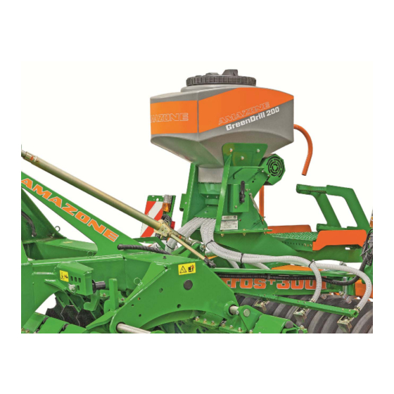
Product description Product description (1) Seed hopper (2) Metering unit with seeding shaft (3) Electric motor for seeding shaft drive (4) Seed delivery hose (5) Fan (6) Baffle plate GreenDrill BAH0108-0 03.20... -
Page 25: Proper Use
Any use other than those listed above, especially mounting the GreenDrill on implements from other manufacturers or AMAZONE implement that are not listed here, is considered as non-intended. Mounting the GreenDrill using the assembly parts that are not intended for the respective implement is also considered non-intended use. -
Page 26: Technical Data
Product description Technical data GreenDrill GreenDrill GreenDrill GreenDrill Catch crop seed drill GD200-E GD200-H GD500-H GD500-D Seed hopper volume [l] Outlets [number] from the Fan drive Electric hydraulic hydraulic carrying implement Metering unit Metering with electrical metering motor Automatic A connection from the control terminal 5.2 to the 7-pin signal seed rate control when socket of the tractor or the radar or GPS device is required. -
Page 27: Ec Declaration Of Incorporation
Any danger for persons due to the mounting of the GreenDrill on the carrying implement must be ruled out in all situations. NOTE AMAZONE is not liable for damage caused by faulty mounting and improper operation of the GreenDrill. The factory plate contains the... -
Page 28: Structure And Function
Structure and function Structure and function The GreenDrill is used for spreading catch crops and re-seeding grass. The seed metered by the seed metering wheels is conveyed into the seed hoses (1). An electrically or hydraulically driven fan (2) produces the air flow to deliver the seed. The GreenDrill GD500-D is fed by the fan of the carrying implement. -
Page 29: Metering
Structure and function Metering 4.1.1 Seeding shaft with seed metering wheels The seed metering wheels are selected based on the seed type. You can find the right seed metering wheel to meter your seed in the seeding tables in the Appendix. Each seed metering wheel is made up of several smaller units. -
Page 30: Seeding Shaft With Fine Seed Metering Wheels Fb-F-Fb-Fb
Structure and function 4.1.1.2 Seeding shaft with fine seed metering wheels fb-f-fb-fb The seeding shaft (1) with 8 fine seed metering wheels fb-f-fb-fb is used for seed with small grain size with low spread rates, e.g. mustard and buckwheat. -
Page 31: Seeding Shaft With Flex 20 Seed Metering Wheels
Structure and function 4.1.1.3 Seeding shaft with Flex 20 seed metering wheels The seeding shaft with 8 Flex 20 seed metering wheels is used for seeds such as Peas Beans. 4.1.1.4 Seeding shaft with Flex 40 seed metering wheels The seeding shaft with 8 Flex 40 seed metering wheels is used for seeds such as ... -
Page 32: Seed Metering Wheel Table
Structure and function 4.1.1.6 Seed metering wheel table GreenDrill BAH0108-0 03.20... -
Page 33: Seeding Shaft Speed
Structure and function 4.1.2 Seeding shaft speed An electric motor drives the seeding shaft. If the control terminal is connected to the 7-pin tractor signal socket with speed sensor or the implement is equipped with a radar or GPS device, the speed of the seeding shaft is automatically adjusted for the working speed. -
Page 34: Calibration Test
Structure and function 4.1.4 Calibration test For calibration and when emptying the seed hopper, the seed drops into the collection bucket via the chute (1). Always perform a calibration test during the initial operation when changing the sort. ... -
Page 35: Agitator Shaft
Structure and function Agitator shaft When spreading seeds with spelt and very light seeds, e.g. grasses, the rotating agitator shaft (1) prevents faulty seeding caused by seed blockage in the seed hopper. With seeds that flow down well, rotation of the agitator shaft is not necessary. -
Page 36: Fan
Structure and function The fan generates a flow of air that conveys the metered material to the baffle plates. The air current becomes stronger with increasing fan speed. A strong flow of air is required for optimal distribution of the seed. If the air flow is too strong, the seed can be damaged on the baffle plates. -
Page 37: Hydraulic Fan Drive
Structure and function 4.4.2 Hydraulic fan drive If your implement is equipped with the hydraulic fan drive, the control terminal shows whether the fan is switched on or off. When the fan is switched on, the red control lamp above the button is illuminated. -
Page 38: Greendrill Gd500-D Without Fan Drive
Structure and function The following maximum values must not be exceeded: Operating pressure of the hydraulic system: max. 210 bar Oil flow rate (tractor pump output): max. 80 l/min. Higher oil flow rates can exceed the maximum permissible fan hydraulic fluid temperature. -
Page 39: Road Safety Bar For The Carrying Implement
Structure and function Road safety bar for the carrying implement With ex-factory deliveries, the brackets for the road safety bar can be mounted differently than described in the operating manual for your carrying implement. If you attach the GreenDrill subsequently onto the carrying implement based on the assembly instructions, it may be necessary to reposition the brackets for the road safety bar. -
Page 40: Implement Settings Before Initial Operation
Implement settings before initial operation Implement settings before initial operation DANGER Danger of crushing, shearing, cutting, being caught or drawn in, winding and knocks through: unintentional lowering of the implement raised using the tractor's three-point hydraulic system. unintentional lowering of raised, unsecured implement parts. -
Page 41: Folding And Unfolding The Ladder Of The Greendrill
Implement settings before initial operation WARNING When using the machine, observe the safety instructions in this operating manual in the operating manual of the carrying implement. CAUTION Never open the seed hopper cover or metering unit cover with the fan running. -
Page 42: Folding The Ladder
Implement settings before initial operation 3.1 Hold the ladder and pull on the lever (1). This releases a latch (2) that represents the mechanical transport locking mechanism. 3.2 Unfold the ladder. 5.1.2 Folding the ladder 1. Fold in the ladder (1). Ensure that the ladder engages in the mechanical transport locking mechanism. -
Page 43: Seeding Without Agitator Shaft Support
Implement settings before initial operation Seeding without agitator shaft support 1. Switch off the control terminal. The agitator shaft (1) should be running when using seeds that tend towards bridge formation. are very light, e.g. grass. 2. Remove the protective cover (1). 2.1 Loosen and remove the 2 hexagonal nuts (2) with the socket wrench (3). -
Page 44: Replacing The Seeding Shaft
Implement settings before initial operation Replacing the seeding shaft 1. Switch off the control terminal. 2. Empty the seed hopper. 3. Remove the protective cover (1). 3.1 Loosen and remove the 2 hexagonal nuts (2) with the socket wrench (3). 4. -
Page 45: Seeding With Flex Seed Metering Wheels
Implement settings before initial operation Seeding with Flex seed metering wheels For the gentle seeding of large seeds, e.g. peas and beans, the flexible Flex seed metering wheels are used (see section "Seeding tables", page 95). The air plate must be removed for seeding with Flex seed metering wheels: 1. -
Page 46: Fill Level Monitoring
Implement settings before initial operation Fill level monitoring A low level sensor (1) monitors the seed level in the seed hopper. If the seed level reaches the low level sensor, an acoustic signal is emitted. At the same time, the control terminal displays a warning message. -
Page 47: Preparing The Implement For Calibration Or For Emptying The Seed Hopper
Implement settings before initial operation Preparing the implement for calibration or for emptying the seed hopper 4. Put the chute (1) into calibration position. 4.1 Loosen the 2 hexagonal bolts (2) with the socket spanner. The spanner is inserted in a holder on the protective cover (see section 5.3, page44). -
Page 48: Hydraulic Fan Drive
Implement settings before initial operation Hydraulic fan drive Before you adjust the fan speed, check the program settings, see section 7.1.1, page 87 section 7.1.7, page 90 section 7.1.8, page 91 5.8.1 Connecting the hydraulic hose lines to the tractor The GreenDrill is equipped with a hydraulic control block with control valve (1). -
Page 49: Setting The Fan Speed On Tractors With Flow Control Valve
Implement settings before initial operation Connect the hydraulic hose lines to the tractor hydraulic system as follows: Pressure line Connection with the label to a single-acting tractor control unit with priority. P (red) Return flow line Connection with the label to an unpressurised tractor connection with direct access to the hydraulic T (yellow) fluid tank. -
Page 50: Setting The Fan Speed On Tractors Without Flow Control Valve
Implement settings before initial operation 5.8.3 Setting the fan speed on tractors without flow control valve Close the control valve (1) of the hydraulic control block before actuating the tractor control unit to prevent damage when the fan over-revs. 1. Close the control valve (1) of the GreenDrill. 1.1 Turn the control valve (1) of the GreenDrill clockwise (-) up to the stop. -
Page 51: Greendrill Control Terminal 5.2
GreenDrill control terminal 5.2 GreenDrill control terminal 5.2 (1) GreenDrill control terminal 5.2 (2) Holder for the control terminal (3) Power cable for 3-pin tractor standard socket (12-volt) (1) Socket (3-pin) for power supply (2) Signal socket (6-pin) for the implement cable The implement cable connects the control terminal with the GreenDrill. -
Page 52: Control Elements
GreenDrill control terminal 5.2 Control elements (1) Graphic display (6) Switch seeding shaft on/off (2) On/Off button (7) The control lamp is illuminated when the seeding shaft is running (3) The control lamp is illuminated when the control terminal is switched on (8) Increase seeding shaft speed (4) Switch the electric fan drive (9) Decrease seeding shaft speed... -
Page 53: Switching The Control Terminal On/Off
GreenDrill control terminal 5.2 Switching the control terminal on/off Switching on the control terminal 1. Instruct any people in the area to stand at a minimum distance of 10 m from the implement. 2. Press the button. The control lamp above the button is illuminated ... -
Page 54: Main Menu
GreenDrill control terminal 5.2 Main menu 6.3.1 During operation - Display without speed sensor Line 1 in the main menu shows the seeding shaft speed [%] set during calibration. Line 2 in the main menu shows the forward speed [km/h] set for calibration. The seeding shaft speed is not adjusted for changing forward speeds. -
Page 55: During Operation - Other Displayed Values
GreenDrill control terminal 5.2 6.3.3 During operation – Other displayed values During operation, the following values are displayed: SW % 50 / 25.0 Seeding shaft speed [%] km/h 20.0 / 10.0 Forward speed [km/h] kg/ha 20.0 Seed rate [kg/ha] Speed 2000 ... -
Page 56: Submenus
GreenDrill control terminal 5.2 Submenus The implement-specific data has already been programmed by your AMAZONE service partner, see section Basic settings by your AMAZONE service partner, page 86. With the buttons, the following submenus can be called up from the main menu: 1. -
Page 57: Calibrating The Seed Rate [Kg/Ha Or Grains/M 2 ]
GreenDrill control terminal 5.2 Calibrating the seed rate [kg/ha or grains/m The seed calibration can be terminated at any time by pressing the button or button. The fan cannot be switched on during calibration. 1. Prepare the implement for the calibration test (see section 5.7, page 47). 2. -
Page 58: Calibration [Kg/Ha]
GreenDrill control terminal 5.2 6.6.1 Calibration [kg/ha] 1. Make all of the entries shown in section 6.6, page 57. 2. Select the display with the buttons. 3. Confirm the selection with the button. 4. Enter the desired spread rate with the buttons (e.g. - Page 59 GreenDrill control terminal 5.2 10. Select the display with the buttons. 11. Confirm the selection with the button. The calibration starts. The seeding shaft begins to rotate (without fan). The seeding shaft stops automatically after the set time has elapsed.
-
Page 60: Calibration [Grains/M ]
GreenDrill control terminal 5.2 6.6.2 Calibration [grains/m 1. Make all of the entries shown in section 6.6, page 57. 2. Select the display with the buttons. 3. Confirm the selection with the button. 4. Enter the desired spread rate (e.g. 100 grains/m with the buttons. - Page 61 GreenDrill control terminal 5.2 14. Select the display with the buttons. 15. Confirm the selection with the button. 16. Using the buttons, set the time 1 during which the seeding shaft will rotate for calibration (e.g. 0.5 min). 17. Confirm the entry with the button.
-
Page 62: Conversion Of The Seed Rate [Grains/M ] In [Kg/Ha]
GreenDrill control terminal 5.2 20. Weigh the collected seed. 21. Select the display with the buttons. 22. Confirm the selection with the button. 23. Enter the weight [kg] of the collected seed on the control terminal using the buttons (e.g. 3.25 kg). 24. -
Page 63: Calibrating The Distance Travelled (Pulses/100 M)
GreenDrill control terminal 5.2 Calibrating the distance travelled (pulses/100 m) The calculation requires the "pulses/100 m" calibration value the travel speed [km/h]. the worked area [ha] (hectare counter). the seeding shaft speed. If the calibration value is not known, it must be determined by means of a "Pulses per 100 m" calibration run. -
Page 64: Calibration By Driving A Calibration Distance
GreenDrill control terminal 5.2 6.7.1 Calibration by driving a calibration distance 1. On the field, measure out a calibration distance of exactly 100 m. Mark the start and end point of the calibration distance. 2. Drive the tractor to the starting position and put the carrying implement into working position. -
Page 65: Calibration By Comparing The Speedometer
GreenDrill control terminal 5.2 6.7.2 Calibration by comparing the speedometer 1. Select the display with the buttons. 2. Confirm the selection with the button. 3. Select the display with the buttons. 4. Confirm the display with the button. 5. Start the tractor for the calibration run. During the calibration run, compare the speeds shown on the display with those on the tractor's speedometer. -
Page 66: Calibration Value - Restoring The Factory Settings (Reset)
GreenDrill control terminal 5.2 6.7.4 Calibration value - Restoring the factory settings (reset) 1. Select the display with the buttons. 2. Confirm the selection with the button. 3. Select the display with the buttons. 4. Confirm the display with the button. -
Page 67: Hectare Counter
GreenDrill control terminal 5.2 Hectare counter Area calculation is carried out using the "actual" forward speed values. The control terminal must be connected to the 7-pin tractor signal socket (see section 6.18.4.1, page 82) or to the radar device (see section 6.18.4.3, page 84) or ... -
Page 68: Operating Hours Counter
GreenDrill control terminal 5.2 Operating hours counter The operating hours counter shows the run time of the seeding shaft. 1. Select the display with the buttons. 2. Confirm the selection with the button. The following are displayed the total hours [h] ... -
Page 69: Adjusting The Fan Speed (Hydraulic Fan Drive)
GreenDrill control terminal 5.2 6.11 Adjusting the fan speed (hydraulic fan drive) The section "Hydraulic fan drive", page 48, describes the adjustment of the fan speed. 6.11.1 Setting the min/max fan speed (hydraulic fan drive) If the fan has a speed sensor, you can set the following parameters: 1. -
Page 70: Operating Voltage
GreenDrill control terminal 5.2 6.12 Operating voltage 1. Select the display with the buttons. 2. Confirm the selection with the button. Display: Operating voltage [volt] Shows the current consumption [amps] of the electrically driven fan motor. Shows the current consumption [amps] of the seeding shaft motor. -
Page 71: Starting Work At The Beginning Of The Field
GreenDrill control terminal 5.2 6.14 Starting work at the beginning of the field Do not switch off the fan during use. Before starting work 1. Close the seed hopper cover. 2. Check if the deflector plates have the same distance. 3. -
Page 72: Turning At End Of The Field
GreenDrill control terminal 5.2 6.15 Turning at end of the field Turning with position signal (working/transport position) The turning procedure takes place automatically when the implement receives the following signals: The implement is in working position The implement is in transport position. To do so, the implement must ... -
Page 73: Emptying The Seed Hopper
GreenDrill control terminal 5.2 6.16 Emptying the seed hopper The seed hopper can be emptied through the menu controls or with the calibration button. 6.16.1 Emptying the seed hopper through the menu controls 1. Prepare the implement for emptying the seed hopper (see section 5.7, page 47). -
Page 74: Error Messages
GreenDrill control terminal 5.2 6.17 Error messages Fault message Description Remedy Control voltage is too low Contact the service partner Operating voltage Minimise the consumers (at least 10 volt) Check the battery undercut, Check the alternator see section "6.12", page 70 ... - Page 75 GreenDrill control terminal 5.2 Fault message Description Remedy Calibration value Repeat the calibration, "pulses per 100 m" is too high (see section 6.7, page 63) The calibration distance Repeat the calibration, is too short (see section 6.7, page 63) "pulses/100 m" Seeding shaft speed is too low.
- Page 76 GreenDrill control terminal 5.2 Fault message Description Remedy Compare the displayed Forward speed too high speed with the actual driven speed Reduce the forward speed or Use larger seed metering wheels Compare the displayed The forward speed is too low speed with the actual driven speed ...
- Page 77 GreenDrill control terminal 5.2 Fault message Description Remedy Back pressure in the return flow with hydraulic drive is too high (see section 5.8.1, and pressure sensor 48). page is not rotating Control lamp without function. The fan is not rotating Switch off control terminal.
- Page 78 GreenDrill control terminal 5.2 Fault Possible fault elimination Change the lifting unit signal Seeding shaft rotates (see section "Entry of the working position sensor signal in transport position source", page 90) Switch on the seeding shaft and start driving Seeding shaft does not rotate in working position ...
- Page 79 GreenDrill control terminal 5.2 Continuous or occasional The speed signal is not being detected forward speed display: 0.0 Set the signal in section 7.1.3 to NO, if all of the settings in the km/h following sections are set to AUTO: section 7.1.3, section 7.1.4 and section 7.1.5 (see...
-
Page 80: Installations And Connections - Control Terminal 5.2
GreenDrill control terminal 5.2 6.18 Installations and connections – Control terminal 5.2 6.18.1 Installation of the control terminal 5.2 Fasten the bracket (1) in the tractor cab with 2 bolts. Bend the bracket so as to provide optimum reading of the display. Insert the control terminal on the bracket in the tractor cab. -
Page 81: Power Cable Connection
GreenDrill control terminal 5.2 6.18.3 Power cable connection 6.18.3.1 Tractor with standard socket (3-pin) Connect the power cable (1) to control terminal and the 3-pin standard socket in the tractor cab. Never connect the 12 volt power supply to the cigarette lighter socket. 6.18.3.2 Tractor without standard socket (3-pin) If the tractor is not equipped with a 3-pin standard socket, have the battery cable retrofitted on your tractor at a specialist workshop. -
Page 82: Signal Sources
GreenDrill control terminal 5.2 6.18.4 Signal sources The control terminal shows the forward speed [km/h] and adjusts the seeding shaft speed according to the changing forward speed. The seed rate [kg/ha] remains unchanged even at varying forward speeds. If it is set correctly, speed differences of 50 % are adjusted up or down. -
Page 83: 6.18.4.2 Working Position Sensor
GreenDrill control terminal 5.2 6.18.4.2 Working position sensor The working position sensor (1) is required when the tractor has a 7-pin signal socket that does not emit a "Working position" signal [see section "Tractor signal socket (7-pin)", page 82]. The working position sensor (1) can be attached on the tractor three-point or on the swivelling running gear of the carrying implement. -
Page 84: 6.18.4.3 Measuring The Forward Speed With The Radar Device
GreenDrill control terminal 5.2 6.18.4.3 Measuring the forward speed with the radar device If the tractor does not have a 7-pin signal socket, control terminal 5.2 requires a working position sensor (see section "Working position sensor", page 83) and ... -
Page 85: 6.18.4.4 Measuring The Forward Speed With The Gps Device
GreenDrill control terminal 5.2 6.18.4.4 Measuring the forward speed with the GPS device If the tractor does not have a 7-pin signal socket, control terminal 5.2 requires a working position sensor (see section "Working position sensor", page 83) and ... -
Page 86: Basic Settings By Your Amazone Service Partner
5.2. The functions can only be activated when the implement configuration is programmed on the control terminal. Have the programming performed by your AMAZONE service partner. Before making any settings, switch off the fan motor and seeding shaft motor. -
Page 87: Fan Drive
Basic settings by your AMAZONE service partner 7.1.1 Fan drive Setting with electric fan drive: ........YES Setting with hydraulic fan drive: ........NO Change the parameters using the buttons. 7.1.2 Seeding shaft signal tone An acoustic warning tone is issued when the seeding shaft is switched on and off. -
Page 88: 7.1.5 Signal Sources
Basic settings by your AMAZONE service partner 7.1.5 Signal sources The control terminal 5.2 requires several signals. The signals are provided either by 7-pin tractor signal socket or the signals come from other sources. The source must be named in the control terminal. - Page 89 Basic settings by your AMAZONE service partner Entry of the forward speed signal source [km/h] The control terminal receives the "Actual forward speed [km/h]" signal through one of the 3 connections: Connection on the 7-pin tractor signal socket or ...
-
Page 90: Acoustic Warning Signal
Basic settings by your AMAZONE service partner Entry of the working position sensor signal source The control terminal receives the "Working/transport position]" signal from the working position sensor (see section 6.18.4.2, 83). page YES, NO or AUTO Change the parameters using the buttons. -
Page 91: Fan Sensor (Hydraulically Driven Fan)
Basic settings by your AMAZONE service partner 7.1.8 Fan sensor (hydraulically driven fan) The hydraulically driven fan either has a pressure sensor (see also section 4.4.2, 37) or page a speed sensor. 12. Fan monitoring Change the parameters using the buttons. -
Page 92: Systems Of Units
Basic settings by your AMAZONE service partner 7.1.10 Systems of units Display Metric system ........(m, ha, km/h, kg) Anglo-American system ....(ft, ac, mph, lb) Change the parameters using the buttons. 7.1.11 Factory settings YES..The factory setting will be restored ... -
Page 93: Cleaning, Maintenance And Repairs
Cleaning, maintenance and repairs Cleaning, maintenance and repairs DANGER Danger of crushing, shearing, cutting, being caught or drawn in, winding and knocks through: unintentional lowering of the implement raised using the tractor's three-point hydraulic system. unintentional lowering of raised, unsecured implement parts. -
Page 94: First Operation
Cleaning, maintenance and repairs First operation Tighten all bolted connections after approx. 20 operating hours, then check these connections every 250 operating hours. Cleaning 1. Empty the seed hopper and metering units. 2. Remove the seeding shaft to thoroughly clean the metering unit. 3. -
Page 95: Seeding Tables
Seeding tables Seeding tables The seeding table values are reference values that can change due to grain shape, grain size, thousand grain weight, and dressing. The exact seeding shaft speed for the required spread rate is derived from the values of the calibration tests. - Page 96 Seeding tables Perennial rye Spread rate Barley Spread rate Seeding shaft speed [%] kg/min. Seeding shaft speed [%] kg/min. 0.46 0.54 0.99 0.87 1.87 1.41 2.74 1.96 3.62 2.51 4.50 3.06 5.33 3.61 6.16 4.16 6.98 4.71 7.81 5.26 8.64 5.81 9.45 6.70...
- Page 97 Seeding tables Wheat Application rate Seeding shaft speed kg/min. kg/min. kg/min. 0.52 0.34 0.48 1.18 0.58 1.03 2.30 0.99 1.95 3.41 1.39 2.68 4.52 1.79 3.78 5.64 2.19 4.69 6.70 2.59 5.61 7.76 2.99 6.52 8.82 3.39 7.44 9.88 3.79 8.35 10.94 4.19...
- Page 98 Seeding tables Buckwheat Spread rate Seeding shaft speed kg/min. kg/min. kg/min. 0.54 0.33 0.27 0.99 0.50 0.70 1.74 0.78 1.40 2.49 1.07 2.11 3.24 1.35 2.82 3.99 1.64 3.53 4.68 1.92 4.23 5.38 2.21 4.94 6.07 2.49 5.65 6.76 2.78 6.36 7.45 3.07...
- Page 99 Seeding tables Oats Spread rate Rapeseed Spread rate Seeding shaft speed [%] kg/min. kg/min. Seeding shaft speed [%] kg/min. kg/min. 0.01 0.15 0.11 0.01 0.02 0.46 0.21 0.02 0.04 0.98 0.38 0.05 0.06 1.50 0.55 0.08 0.07 2.02 0.72 0.10 0.09 2.54 0.89...
- Page 100 Seeding tables White mustard Spread rate Fodder radish Spread rate Seeding shaft speed [%] kg/min. Seeding shaft speed [%] kg/min. 0.04 0.66 0.15 1.18 0.33 2.05 0.50 2.92 0.68 3.79 0.86 4.66 1.00 1.15 1.29 1.43 1.58 1.65 1.72 1.79 1.86 1.93 2.00...
- Page 101 Seeding tables Phacelia Spread rate Grass Spread rate Seeding shaft speed [%] kg/min. Seeding shaft speed [%] kg/min. 0.14 0.27 0.31 0.61 0.61 1.17 0.90 1.73 1.19 2.30 1.49 2.86 1.52 3.42 1.56 3.98 1.59 4.55 1.63 5.11 1.66 5.67 1.75 6.23 1.85...
- Page 102 Seeding tables Lupins Spread rate Lucerne Spread rate Seeding shaft speed [%] kg/min. Seeding shaft speed [%] kg/min. 0.42 0.10 1.11 0.21 2.26 0.40 3.41 0.60 4.56 0.79 5.71 0.98 6.87 1.15 8.03 1.32 9.19 1.49 10.35 1.65 11.51 1.82 12.48 1.86 13.44...
- Page 103 Seeding tables Red clover Spread rate Vetches Spread rate Seeding shaft speed [%] kg/min. Seeding shaft speed [%] kg/min. 0.04 0.76 0.15 1.42 0.33 2.51 0.51 3.61 0.70 4.71 0.88 5.81 1.06 1.23 1.41 1.58 1.76 1.82 1.87 1.93 1.98 2.04 2.09 2.15...
- Page 104 Seeding tables Peas Spread rate Field (broad) beans Application rate Seeding shaft speed [%] kg/min. kg/min. Seeding shaft speed [%] kg/min. kg/min. 0.46 0.95 0.46 1.02 0.67 1.45 0.66 1.57 1.02 2.29 1.00 2.49 1.37 3.12 1.34 3.40 1.72 3.96 1.68 4.32 2.07...
- Page 106 H. DREYER GmbH & Co. KG Postfach 51 Tel.: + 49 (0) 5405 501-0 D-49202 Hasbergen-Gaste email: amazone@amazone.de Germany http:// www.amazone.de...
Need help?
Do you have a question about the GreenDrill GD200-E and is the answer not in the manual?
Questions and answers