Amazone GreenDrill GD200-E Operating Manual
Catch crop seed drill
Hide thumbs
Also See for GreenDrill GD200-E:
- Operating manual (118 pages) ,
- Operating manual (106 pages)
Table of Contents

Related Manuals for Amazone GreenDrill GD200-E


Summary of Contents for Amazone GreenDrill GD200-E
- Page 1 Operating Manual Catch Crop Seed Drill GreenDrill GD200-E / GD200-H GreenDrill GD500-H / GD500-D Read and comply with this operating manual before initial operation. MG7636 Keep it in a safe place for future use. BAH0108-0 03.20...
- Page 3 + 49 (0) 5405 50 1-0 Email: amazone@amazone.de Ordering spare parts Spare parts lists are freely accessible in the spare parts portal at www.amazone.de. Please send orders to your AMAZONE dealer. Formalities of the operating manual Type: ---------------------------------- GreenDrill Document number: ---------------- MG7636 Compilation date: ----------------- 03.20...
-
Page 4: Table Of Contents
Product description .................. 24 Intended use .......................... 25 3.1.1 Approved AMAZONE carrying implements ................25 Technical data ........................26 Rating plate and CE-mark ..................... 26 EC Declaration of Incorporation .................... 27 ... - Page 5 Replacing the seeding shaft ....................44 Seeding with Flex seed metering wheels ................45 Fill level monitoring ........................ 46 Filling the seed hopper ......................46 Preparing the implement for calibration or for emptying the seed hopper ......47 ...
- Page 6 Basic settings by your AMAZONE service partner ........ 86 Opening the "Basic settings" program .................. 86 7.1.1 Fan drive ..........................87 7.1.2 Seeding shaft signal tone ...................... 87 7.1.3 Implement wheel sensor ....................... 87 ...
-
Page 7: User Information
User information User information The User information section provides information concerning the operating manual. This operating manual is valid for all versions of the implement. Figures are provided as a reference and are to be understood as representations of the principle. All of the equipment is described without designating it as special equipment. -
Page 8: General Safety Notices
General safety notices General safety notices This section contains supplementary information on the safety notices in the operating manual to ensure safe operation of the implement. Obligations and liability Comply with the notices in the operating manual Knowledge of the basic safety notices and safety regulations is a fundamental requirement for safe handling and fault-free machine operation. - Page 9 General safety notices Risks involved in handling the machine The machine has been constructed in accordance with the state-of-the art and the acknowledged safety standards. Nevertheless, when using the machine, risks and impairments can arise for the health and safety of the user or third parties ...
-
Page 10: Presentation Of Safety Symbols
General safety notices Presentation of safety symbols Safety notices are indicated by the triangular safety symbol and the highlighted signal word. The signal word (DANGER, WARNING, CAUTION) describes the severity of the risk, and has the following meaning: DANGER Indicates a direct hazard with high risk that will result in death or serious injury (loss of limbs or long-term harm), if not prevented. -
Page 11: Organizational Measures
General safety notices Organizational measures The owner must provide the necessary personal protective equipment, such as: Protective goggles Safety footwear Chemical-resistant overalls Skin protection agents, etc. The operating manual: must always be kept where the implement is operated. ... -
Page 12: Training Of Personnel
General safety notices Training of personnel Only trained and instructed persons are allowed to work with/on the machine. The owner must clearly specify the responsibilities of the persons assigned to operate, maintain, and repair the machine. Personnel in training are only allowed to work with/on the machine under the supervision of an experienced person. -
Page 13: Safety Measures In Normal Operation
General safety notices Safety measures in normal operation Only operate the machine if all the safety devices and protective devices are fully functional. Check the implement at least once a day for apparent damage and function of the safety devices and protective devices. -
Page 14: Structural Modifications
Immediately replace any machine parts that are not in perfect condition. Only use genuine AMAZONE spare parts and wear parts, or spare parts and wear parts approved by AMAZONEN-WERKE, so that the type approval remains valid in accordance with national and international regulations. -
Page 15: Warning Symbols On The Implement
Warning symbols on the implement Always keep all the warning symbols on the implement clean and in a legible condition! Replace illegible warning symbols. You can request the warning symbols from your AMAZONE dealer using the order number (e.g., MD075). Structure Warning symbols indicate danger areas on the implement and warn of residual dangers. - Page 16 General safety notices MD 076 Risk of hands or arms being caught or drawn into the implement due to moving parts involved in force transmission. This hazard can cause the most severe injuries with loss of body parts. Never open or remove protective devices, ...
- Page 17 General safety notices MD 082 Risk of falling for persons standing on the implement steps or platforms, while the implement is in motion! There is a risk of severe injuries, possibly with fatal consequences. Conveying persons on the implement and/or climbing on the implement in operation are prohibited.
-
Page 18: Placement Of The Warning Symbols
General safety notices MD 102 Danger through intervention on the implement, through tasks involving installation, adjustment, troubleshooting, cleaning, maintenance, and repair, due to the tractor and the implement starting unintentionally and rolling! These hazards can cause serious injuries, possibly with fatal consequences. ... -
Page 19: Safety Notices For The Operator
General safety notices 2.14 Safety notices for the operator Switch off the control terminal Prior to road transport Prior to adjustment, maintenance, and repair tasks. Risk of accident due to unintentional activation of the metering unit or other implement components. 2.14.1 General safety instructions and accident prevention instructions ... - Page 20 General safety notices Use of the machine Before starting work, ensure that you understand all the devices and control elements of the implement and their functions. When the implement is in operation, it is too late to do this. ...
-
Page 21: Hydraulic System
Have the hydraulic hose lines checked for safe working condition by a specialist at least once a year. Replace the hydraulic hose lines if they are damaged or worn. Use only original AMAZONE hydraulic hose lines. The hydraulic hose lines should not be used for longer than six years, including any storage time of maximum two years. -
Page 22: Electrical System
General safety notices 2.14.3 Electrical system For tasks on the electrical system, always disconnect the battery (negative terminal). Only use the prescribed fuses. If fuses are used with amperage that is too high, the electrical system will be destroyed – fire hazard. ... -
Page 23: Cleaning, Maintenance, And Repair
Disconnect the cable to the tractor generator and battery, before carrying out electrical welding tasks on the tractor or on attached implements. Spare parts must meet at least the technical requirements specified by AMAZONEN-WERKE. This is ensured through use of original AMAZONE spare parts. GreenDrill BAH0108-0 03.20... -
Page 24: Product Description
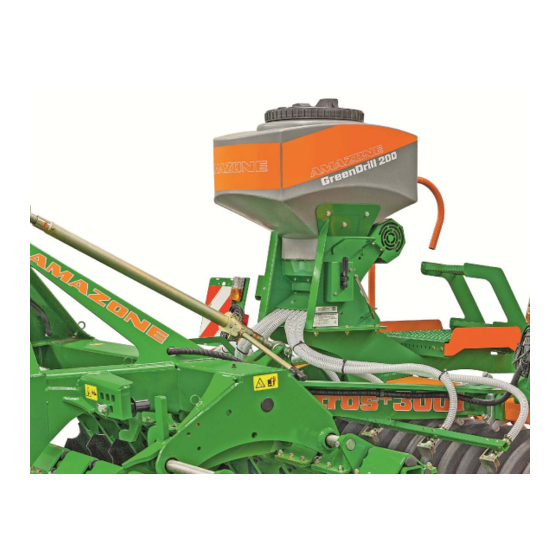
Product description Product description (1) Seed hopper (2) Metering unit with seeding shaft (3) Electric motor for seed shaft drive (4) Seed delivery hose (5) Fan (6) Baffle plate GreenDrill BAH0108-0 03.20... -
Page 25: Intended Use
Any use not listed above, especially mounting the GreenDrill on implements from other manufacturers or on AMAZONE implements that are not listed here, is considered non-intended use. Mounting the GreenDrill using the mounting parts that are not intended for the respective implement is also considered non-intended use. -
Page 26: Technical Data
Product description Technical data GreenDrill GreenDrill GreenDrill GreenDrill Catch Crop Seed Drill GD200-E GD200-H GD500-H GD500-D Seed hopper volume [gal] / [l] 52.83 / 200 52.83 / 200 132.1 / 500 132.1 / 500 Outlets [number] from the Fan drive Electric Hydraulic Hydraulic... -
Page 27: Ec Declaration Of Incorporation
Any danger for personnel due to the mounting of the GreenDrill on the carrying implement must be ruled out in all situations. NOTE AMAZONE is not liable for damage caused by faulty mounting and improper operation of the GreenDrill. The factory plate contains the... -
Page 28: Structure And Function
Structure and function Structure and function The GreenDrill is used for spreading catch crops and re-seeding grass. The seed metered by the seed metering wheels is conveyed into the seed tubes (1). An electrically or hydraulically driven fan (2) produces the air flow to deliver the seed. The GreenDrill GD500-D is fed by the fan of the carrying implement. -
Page 29: Dosing
Structure and function Dosing 4.1.1 Seeding shaft with seed metering wheels The seed metering wheels are selected based on the seed type. You can find the right seed metering wheel to meter your seed in the seeding tables in the Appendix. Each seed metering wheel is made up of several smaller units. -
Page 30: Seeding Shaft With Fine Seed Metering Wheels Fb-F-Fb-Fb
Structure and function 4.1.1.2 Seeding shaft with fine seed metering wheels fb-f-fb-fb The seeding shaft (1) with 8 fine seed metering wheels fb-f-fb-fb is used for seed with small grain size with low spread rates, e.g. mustard and buckwheat. -
Page 31: Seeding Shaft With Flex 20 Seed Metering Wheels
Structure and function 4.1.1.3 Seeding shaft with Flex 20 seed metering wheels The seeding shaft with 8 Flex 20 seed metering wheels is used for seeds such as Peas Beans 4.1.1.4 Seeding shaft with Flex 40 seed metering wheels The seeding shaft with 8 Flex 40 seed metering wheels is used for seeds such as ... - Page 32 Structure and function 4.1.1.6 Table – seed metering wheels GreenDrill BAH0108-0 03.20...
-
Page 33: Seeding Shaft Speed
Structure and function 4.1.2 Seeding shaft speed An electric motor drives the seeding shaft. If the control terminal is connected to the 7-pin tractor signal socket with speed sensor or if the implement is equipped with a radar or GPS device, the speed of the seeding shaft is automatically adapted to the working speed. -
Page 34: Calibration
Structure and function 4.1.4 Calibration For calibration and when emptying the seed hopper, the seed drops into the collection bucket via the chute (1). Always perform the calibration: At initial commissioning When changing the seed type If the same type is used, but of a different quality and specific weight. ... -
Page 35: Agitator Shaft
Structure and function Agitator shaft When sowing spelt and very light seeds, e.g. grasses, the rotating agitator shaft (1) prevents faulty seeding caused by seed blockage in the seed hopper. With seeds that flow down well, rotation of the agitator shaft is not necessary. Seeding with Flex seed metering wheels For gentle seeding of large seeds, e.g. -
Page 36: Fan
Structure and function The fan generates an air flow that conveys the metered material to the coulters. The air flow becomes stronger with increasing fan speed. A strong air flow is required for optimal distribution of the seed. If the air flow is too strong, the seed can be damaged on the baffle plates. -
Page 37: Hydraulic Fan Drive
Structure and function 4.4.2 Hydraulic fan drive If your implement is equipped with the hydraulic fan drive, the control terminal shows whether the fan is switched on or off. When the fan is switched on, the red control lamp above the button is illuminated. -
Page 38: Greendrill Gd500-D Without Fan Drive
Structure and function Do not exceed the following maximum values: Operating pressure of the hydraulic system: max. 3045.8 psi / 210 bar Fluid flow rate (tractor pump max. 213.13 gpm / 80 capacity): l/min. Higher fluid flow rates can exceed the maximum permissible fan hydraulic fluid temperature. -
Page 39: Road Safety Bar For The Carrying Implement
Structure and function Road safety bar for the carrying implement With ex-factory deliveries, the holders for the road safety bar may be mounted differently than described in the operating manual for your carrying implement. If you subsequently fasten the GreenDrill onto the carrying implement based on the mounting instructions, it may be necessary to reposition the holders for the road safety bar. -
Page 40: Implement Settings Before Initial Operation
Implement settings before initial operation Implement settings before initial operation DANGER Danger of crushing, shearing, cutting, severing, entrapment, winding, entanglement, catching, and impact, due to: unintentional lowering of the implement that has been lifted out via the tractor's 3-point hydraulic system. ... -
Page 41: Folding And Unfolding The Ladder Of The Greendrill
Implement settings before initial operation WARNING When using the implement, comply with the safety instructions in this operating manual in the operating manual of the carrying implement. CAUTION Never open the seed hopper cover or metering unit cover when the fan is running. -
Page 42: Folding The Ladder
Implement settings before initial operation 3.1 Hold the ladder firmly and pull the lever (1). This releases a latch (2) which is the mechanical transport locking mechanism of the ladder. 3.2 Unfold the ladder. 5.1.2 Folding the ladder 1. Fold the ladder (1). Ensure that the ladder engages in the mechanical transport locking mechanism. -
Page 43: Seeding Without Agitator Shaft Support
Implement settings before initial operation Seeding without agitator shaft support 1. Switch off the control terminal. The agitator shaft (1) should be running when using seeds that have a tendency to form bridges. are very light, e.g. grasses. 2. -
Page 44: Replacing The Seeding Shaft
Implement settings before initial operation Replacing the seeding shaft 1. Switch off the control terminal. 2. Empty the seed hopper. 3. Remove the protective hood (1). 3.1 Unscrew and remove the 2 hex nuts (2) with the socket wrench (3). 4. -
Page 45: Seeding With Flex Seed Metering Wheels
Implement settings before initial operation Seeding with Flex seed metering wheels For gentle seeding of large seeds, e.g. peas and beans, the flexible Flex seed metering wheels are used (see section "Seeding tables", page 95). The air plate must be removed for seeding with Flex seed metering wheels: 1. -
Page 46: Fill Level Monitoring
Implement settings before initial operation Fill level monitoring A low level sensor (1) monitors the seed level in the seed hopper. If the seed level reaches the low level sensor, an acoustic signal is emitted. At the same time, the control terminal displays a warning message. -
Page 47: Preparing The Implement For Calibration Or For Emptying The Seed Hopper
Implement settings before initial operation Preparing the implement for calibration or for emptying the seed hopper 4. Bring the chute (1) into calibration position. 4.1 Unscrew the 2 hex bolts (2) with the socket wrench. The wrench is inserted in a holder on the protective hood (see section 5.3, page 44). -
Page 48: Hydraulic Fan Drive
Implement settings before initial operation Hydraulic fan drive Before adjusting the fan speed, check the program settings, see section 7.1.1, page 87 section 7.1.7, page 90 section 7.1.8, page 91 5.8.1 Connecting the hydraulic hose lines on the tractor The GreenDrill has a hydraulic control block with control valve (1). -
Page 49: Adjusting The Fan Speed For Tractors With Flow Control Valve
Implement settings before initial operation Connect the hydraulic hose lines to the tractor hydraulic system as follows: Pressure line Connection with the P to a single-acting tractor control unit with priority. mark (red) Return flow line Connection with the T to an unpressurized tractor connection with direct access to the hydraulic mark (yellow) fluid tank. -
Page 50: Adjusting The Fan Speed For Tractors Without Flow Control Valve
Implement settings before initial operation 5.8.3 Adjusting the fan speed for tractors without flow control valve Close the control valve (1) of the hydraulic control block before activating the tractor control unit, to prevent damage when the fan over-revs. 1. Close the control valve (1) of the GreenDrill. 1.1 Turn the control valve (1) of the GreenDrill clockwise (-) to the stop. -
Page 51: Greendrill Control Terminal 5.2
GreenDrill control terminal 5.2 GreenDrill control terminal 5.2 (1) GreenDrill control terminal 5.2 (2) Holder for the control terminal (3) Power cable for 3-pin tractor standard socket (12-volt) (1) Socket (3-pin) for power supply (2) Signal socket (6-pin) for the implement cable The implement cable connects the control terminal to the GreenDrill. -
Page 52: Control Elements
GreenDrill control terminal 5.2 Control elements (1) Graphic display (6) Switch seeding shaft on/off (2) On/Off button (7) The control lamp is illuminated when the seeding shaft is running (3) The control lamp is illuminated when the control terminal is switched on (8) Increase seeding shaft speed (4) Switch the electric fan drive (9) Decrease seeding shaft speed... -
Page 53: Switching The Control Terminal On/Off
GreenDrill control terminal 5.2 Switching the control terminal on/off Switching on the control terminal 1. Instruct any people in the area to move at least 65.62 ft / 20 m away from the implement. 2. Press the button The control lamp above the button is illuminated ... -
Page 54: Main Menu
GreenDrill control terminal 5.2 Main menu 6.3.1 During operation – display without speed sensor Line 1 in the main menu shows the seeding shaft speed [%] set at calibration. Line 2 in the main menu shows the forward speed [mph] / [km/h] set for calibration. The seeding shaft speed does not adapt to the changing forward speeds. -
Page 55: During Operation - Other Displayed Values
GreenDrill control terminal 5.2 6.3.3 During operation – other displayed values During operation, the following values are displayed: SP % 50 / 25.0 Seeding shaft speed [%] km/h 20.0 / 10.0 Forward speed: [mph] / [km/h] kg/ha 20.0 ... -
Page 56: Submenus
GreenDrill control terminal 5.2 Submenus Your AMAZONE service partner has already programmed the implement-specific data, see section "Basic settings by your AMAZONE service partner", page 86. Use the buttons, to call up the following submenus from the main menu: 1. Language 2. -
Page 57: Calibrating The Seed Rate [Lb/Ac Or Kernel/Ft²]
GreenDrill control terminal 5.2 Calibrating the seed rate [lb/ac or kernel/ft²] Seed calibration can be terminated at any time by pressing the button or the button. The fan cannot be switched on during calibration. 1. Prepare the implement for calibration (see section 5.7, page 47). 2. -
Page 58: Calibration [Lb/Ac]
GreenDrill control terminal 5.2 6.6.1 Calibration [lb/ac] 1. Make all of the entries shown in section 6.6, page 57. 2. Use the buttons to select the display. 3. Use the button to confirm the selection. 4. Use the buttons to enter the desired spread rate (e.g. - Page 59 GreenDrill control terminal 5.2 10. Use the buttons to select the display. 11. Use the button to confirm the selection. Calibration starts. The seeding shaft begins to rotate (without fan). The seeding shaft stops automatically after the set time has elapsed.
-
Page 60: Calibration [Kernel/Ft²]
GreenDrill control terminal 5.2 6.6.2 Calibration [kernel/ft²] 1. Make all of the entries shown in section 6.6, page 57. 2. Use the buttons to select the display. 3. Use the button to confirm the selection. 4. Use the buttons to enter the desired spread rate (e.g. 9.29 kernel/ft²... - Page 61 GreenDrill control terminal 5.2 14. Use the buttons to select the display. 15. Use the button to confirm the selection. 16. Use the buttons, to set the time 1 in which the seeding shaft will rotate for calibration (e.g. 0.5 min). 17.
-
Page 62: Seed Rate Conversion
GreenDrill control terminal 5.2 20. Weigh the collected seed. 21. Use the buttons to select the display. 22. Use the button to confirm the selection. 23. Use the buttons to enter the weight [lb] / [kg] of the collected seed in the control terminal (e.g. 7.16 lb / 3.25 kg). 24. -
Page 63: Calibrating The Distance Traveled (Pulses/328 Ft (100 M))
GreenDrill control terminal 5.2 Calibrating the distance traveled (pulses/328 ft (100 m)) The calibration value "pulses/328 ft (100 m)" is required for calibration of the forward speed [mph] / [km/h] of the worked area [ac] / [ha] (hectare counter) ... -
Page 64: Calibration By Driving A Calibration Distance
GreenDrill control terminal 5.2 6.7.1 Calibration by driving a calibration distance 1. On the field, measure off a calibration distance of precisely 328.1 feet / 100 m. Mark the start point and end point of the calibration distance. 2. Bring the tractor to the starting position and bring the carrying implement into working position. -
Page 65: Calibration By Speedometer Comparison
GreenDrill control terminal 5.2 6.7.2 Calibration by speedometer comparison 1. Use the buttons to select the display. 2. Use the button to confirm the selection. 3. Use the buttons to select the display. 4. Use the button to confirm the display. 5. -
Page 66: Calibration Value - Restoring The Factory Settings (Reset)
GreenDrill control terminal 5.2 6.7.4 Calibration value – restoring the factory settings (reset) 1. Use the buttons to select the display. 2. Use the button to confirm the selection. 3. Use the buttons to select the display. 4. Use the button to confirm the display. -
Page 67: Hectare Counter
GreenDrill control terminal 5.2 Hectare counter Area calculation is carried out using the "Actual" forward speed values. The control terminal must be connected. to the 7-pin tractor signal socket (see section 6.18.4.1, page 82) or to the radar device (see section 6.18.4.3, page 84) or ... -
Page 68: Operating Hours Counter
GreenDrill control terminal 5.2 Operating hours counter The operating hours counter shows the runtime of the seeding shaft. 1. Use the button to select the display. 2. Use the button to confirm the selection. The following are displayed the total hours [h] ... -
Page 69: Adjusting The Fan Speed (Hydraulic Fan Drive)
GreenDrill control terminal 5.2 6.11 Adjusting the fan speed (hydraulic fan drive) The section "Hydraulic fan drive", page 48, describes the adjustment of the fan speed. 6.11.1 Setting the min./max. fan speed (hydraulic fan drive) If the fan has a speed sensor, you can set the following parameters: 1. -
Page 70: Operating Voltage
GreenDrill control terminal 5.2 6.12 Operating voltage 1. Use the button to select the display. 2. Use the button to confirm the selection. Display: Operating voltage [volt] Shows the current draw [amps] of the electrically driven fan motor. Shows the current draw [amps] of the seeding shaft motor. -
Page 71: Starting Work At The Beginning Of The Field
GreenDrill control terminal 5.2 6.14 Starting work at the beginning of the field Do not switch off the fan during use. Before starting work 1. Close the seed hopper cover. 2. Check whether the deflector plates have the same spacing. 3. -
Page 72: Turning At The End Of The Field
GreenDrill control terminal 5.2 6.15 Turning at the end of the field Turning with position signal (working position / transport position) The turning procedure takes place automatically when the implement receives the following signals: Implement is in working position ... -
Page 73: Emptying The Seed Hopper
GreenDrill control terminal 5.2 6.16 Emptying the seed hopper The seed hopper can be emptied via menu control or via the calibration button. 6.16.1 Emptying the seed hopper through menu control 1. Prepare the implement for emptying of the seed hopper (see section 5.7, page 47). -
Page 74: Error Messages
GreenDrill control terminal 5.2 6.17 Error messages Error message Description Remedy Control voltage is too low Contact service partner Operating voltage Minimize consumers does not reach Check battery (at least 10 volts) Check alternator see section "6.12", page 70 ... - Page 75 GreenDrill control terminal 5.2 Error message Description Remedy Calibration value Repeat calibration, "pulses/328 ft (100 m)" is too (see section 6.7, page 63) large Distance travelled Repeat calibration, too short for calibration (see section 6.7, page 63) "pulses/328 ft (100 m)" Seeding shaft speed is too low.
- Page 76 GreenDrill control terminal 5.2 Error message Description Remedy Compare the displayed Forward speed is too high speed with the actual driven speed Reduce the forward speed Use larger seed metering wheels Compare the displayed Forward speed too low speed with the actual driven speed ...
- Page 77 GreenDrill control terminal 5.2 Error message Description Remedy Back pressure in the return flow with hydraulic drive is too high (see section 5.8.1, and pressure sensor page 48). does not rotate Control lamp without function. Fan does not rotate Switch off control terminal.
- Page 78 GreenDrill control terminal 5.2 Fault Possible fault rectification Change the lifting unit signal Seeding shaft rotates (see section "Entry of the signal source – working position in transport position sensor", page 90) Switch on the seeding shaft and start driving Seeding shaft does not rotate in working position ...
- Page 79 GreenDrill control terminal 5.2 Continuous or intermittent The speed signal is not detected forward speed display: 0.0 Set the signal in section 7.1.3 to NO, if all of the settings in the mph / km/h following sections are set to AUTO: section 7.1.3, Section 7.1.4 and section 7.1.5 (see...
-
Page 80: Installations And Connections - Control Terminal 5.2
GreenDrill control terminal 5.2 6.18 Installations and connections – control terminal 5.2 6.18.1 Installation of the control terminal 5.2 Fasten the holder (1) in the tractor cab with 2 bolts. Bend the holder appropriately for optimal read- out of the display. Fit the control terminal onto the holder in the tractor cab. -
Page 81: Power Cable Connection
GreenDrill control terminal 5.2 6.18.3 Power cable connection 6.18.3.1 Tractor with standard socket (3-pin) Connect the power cable (1) to the control terminal and to the 3-pin standard socket in the tractor cab. Never connect the 12 volt power supply to the cigarette lighter socket. 6.18.3.2 Tractor without standard socket (3-pin) If the tractor is not equipped with a 3-pin standard socket, have the battery cable retrofitted on your tractor in a specialist workshop. -
Page 82: Signal Sources
GreenDrill control terminal 5.2 6.18.4 Signal sources The control terminal shows the forward speed [mph] / [km/h] and adapts the seeding shaft speed to the changing forward speed. The seed rate [lb/ac] / [kg/ha] remains unchanged, even at changing forward speeds. If adjusted correctly, speed differences of 50% are compensated upward or downward. -
Page 83: 6.18.4.2 Working Position Sensor
GreenDrill control terminal 5.2 6.18.4.2 Working position sensor The working position sensor (1) is required when the tractor has a 7-pin signal socket that does not emit a "Working position" signal [see section "Tractor signal socket (7-pin)", page 82]. The working position sensor (1) can be attached on the tractor three-point or on the pivoting running gear of the carrying implement. -
Page 84: 6.18.4.3 Measuring The Forward Speed With The Radar Device
GreenDrill control terminal 5.2 6.18.4.3 Measuring the forward speed with the radar device If the tractor does not have a 7-pin signal socket, the control terminal 5.2 requires a working position sensor (see section "Working position sensor", page 83) and ... -
Page 85: 6.18.4.4 Measuring The Forward Speed With The Gps Device
GreenDrill control terminal 5.2 6.18.4.4 Measuring the forward speed with the GPS device Das v erk nüpfte Bild k ann nicht angezeigt werden. Möglicherweise wurde die Datei v erschoben, umbenannt oder gelöscht. Stellen Sie sicher, dass die Verk nüpfung auf die k orrek te Datei und den k orrek ten Speicherort zeigt. If the tractor does not have a 7-pin signal socket, the control terminal 5.2 requires ... -
Page 86: Basic Settings By Your Amazone Service Partner
5.2. The functions can only be activated when the implement configuration is programmed on the control terminal. Have the programming executed by your AMAZONE service partner. Before making any settings, switch off the fan motor and seeding shaft motor. -
Page 87: Fan Drive
Basic settings by your AMAZONE service partner 7.1.1 Fan drive Setting for electric fan drive: .......... YES Setting for electric fan drive: .......... NO Use the buttons to change the parameters. 7.1.2 Seeding shaft signal tone An acoustic warning tone is emitted when the seeding shaft is switched on and off. -
Page 88: Signal Sources
Basic settings by your AMAZONE service partner 7.1.5 Signal sources The control terminal 5.2 requires several signals. The signals are provided either by the 7-pin tractor signal socket or the signals come from other sources. The source must be named in the control terminal. - Page 89 Basic settings by your AMAZONE service partner Entry of the signal source – forward speed [mph] / [km/h] The control terminal receives the "Actual forward speed [mph] / [km/h]" signal through one of the 3 connections: Connection on the 7-pin tractor signal socket or ...
-
Page 90: Acoustic Warning Signal
Basic settings by your AMAZONE service partner Entry of the signal source – working position sensor The control terminal receives the "Working position / transport position]" signal from the working position sensor (see section 6.18.4.2, page 83). YES, NO or AUTO Use the buttons to change the parameters. -
Page 91: Fan Sensor (Hydraulically Driven Fan)
Basic settings by your AMAZONE service partner 7.1.8 Fan sensor (hydraulically driven fan) The hydraulically driven fan either has a pressure sensor (see also section 4.4.2, page 37) or a speed sensor. 12. Fan monitor Use the buttons to change the parameters. -
Page 92: Systems Of Units
Basic settings by your AMAZONE service partner 7.1.10 Systems of units Display Metric system ........(m, ha, km/h, kg) Anglo-American system ....(ft, ac, mph, lb) Use the buttons to change the parameters. 7.1.11 Factory settings YES..The factory settings will be restored ... -
Page 93: Cleaning, Maintenance And Repair
Cleaning, maintenance and repair Cleaning, maintenance and repair DANGER Danger of crushing, shearing, cutting, severing, entrapment, winding, entanglement, catching, and impact, due to: unintentional lowering of the implement that has been lifted out via the tractor's 3-point hydraulic system. ... -
Page 94: First Use
Cleaning, maintenance and repair First use Retighten all bolted connections after approx. 20 operating hours; thereafter check these connections every 250 operating hours. Cleaning 1. Empty the seed hopper and metering units. 2. Remove the seeding shaft to thoroughly clean the metering unit. 3. -
Page 95: Seeding Tables
Seeding tables Seeding tables The seeding table values are reference values that can change due to grain shape, grain size, thousand grain weight, and dressing. The exact seeding shaft speed for the required spread rate is derived from the values of the calibration tests. - Page 96 Seeding tables Perennial rye Spread rate Barley Spread rate Seeding shaft speed [%] lb/min. (kg/min.) Seeding shaft speed [%] lb/min. (kg/min.) 1.02 (0.46) 1.19 (0.54) 2.18 (0.99) 1.92 (0.87) 4.12 (1.87) 3.11 (1.41) 6.04 (2.74) 4.32 (1.96) 7.98 (3.62) 5.53 (2.51) 9.92 (4.50) 6.75 (3.06) 11.75 (5.33)
- Page 97 Seeding tables Wheat Spread rate Seeding shaft speed lb/min. (kg/min.) lb/min. (kg/min.) lb/min. (kg/min.) 1.15 (0.52) 0.75 (0.34) 1.06 (0.48) 2.60 (1.18) 1.28 (0.58) 2.27 (1.03) 5.07 (2.30) 2.18 (0.99) 4.30 (1.95) 7.52 (3.41) 3.06 (1.39) 5.91 (2.68) 9.96 (4.52) 3.95 (1.79) 8.33 (3.78) 12.43 (5.64)
- Page 98 Seeding tables Buckwheat Spread rate Seeding shaft speed lb/min. (kg/min.) lb/min. (kg/min.) lb/min. (kg/min.) 1.19 (0.54) 0.73 (0.33) 0.60 (0.27) 2.18 (0.99) 1.10 (0.50) 1.54 (0.70) 3.84 (1.74) 1.72 (0.78) 3.09 (1.40) 5.49 (2.49) 2.35 (1.07) 4.65 (2.11) 7.14 (3.24) 2.98 (1.35) 6.21 (2.82) 8.80 (3.99)
- Page 99 Seeding tables Oats Spread rate Canola Spread rate Seeding shaft speed lb/min. lb/min. lb/min. lb/min. Seeding shaft speed [%] (kg/min.) (kg/min.) (kg/min.) (kg/min.) 0.02 0.33 0.24 0.02 (0.01) (0.15) (0.11) (0.01) 0.04 1.01 0.47 0.04 (0.02) (0.46) (0.21) (0.02) 0.09 2.16 0.84 0.11...
- Page 100 Seeding tables White mustard Spread rate Fodder radish Spread rate Seeding shaft speed lb/min. (kg/min.) Seeding shaft speed [%] lb/min. (kg/min.) 0.09 (0.04) 1.46 (0.66) 0.33 (0.15) 2.60 (1.18) 0.73 (0.33) 4.52 (2.05) 1.10 (0.50) 6.44 (2.92) 1.50 (0.68) 8.36 (3.79) 1.90 (0.86) 10.27 (4.66) 2.20 (1.00)
- Page 101 Seeding tables Phacelia Spread rate Grass Spread rate Seeding shaft speed lb/min. (kg/min.) Seeding shaft speed [%] lb/min. (kg/min.) 0.31 (0.14) 0.60 (0.27) 0.68 (0.31) 1.34 (0.61) 1.34 (0.61) 2.58 (1.17) 1.98 (0.90) 3.81 (1.73) 2.62 (1.19) 5.07 (2.30) 3.28 (1.49) 6.30 (2.86) 3.35 (1.52) 7.54 (3.42)
- Page 102 Seeding tables Lupines Spread rate Lucerne Spread rate Seeding shaft speed lb/min. (kg/min.) Seeding shaft speed [%] lb/min. (kg/min.) 0.93 (0.42) 0.22 (0.10) 2.45 (1.11) 0.46 (0.21) 4.98 (2.26) 0.88 (0.40) 7.52 (3.41) 1.32 (0.60) 10.05 (4.56) 1.74 (0.79) 12.59 (5.71) 2.16 (0.98) 15.14 (6.87) 2.54 (1.15)
- Page 103 Seeding tables Red clover Spread rate Vetches Spread rate Seeding shaft speed lb/min. (kg/min.) Seeding shaft speed [%] lb/min. (kg/min.) 0.09 (0.04) 1.68 (0.76) 0.33 (0.15) 3.13 (1.42) 0.73 (0.33) 5.53 (2.51) 1.12 (0.51) 7.96 (3.61) 1.54 (0.70) 10.38 (4.71) 1.94 (0.88) 12.81 (5.81) 2.34 (1.06)
- Page 104 Seeding tables Peas Spread rate Field (broad) beans Spread rate Seeding shaft speed lb/min. lb/min. lb/min. lb/min. Seeding shaft speed [%] (kg/min.) (kg/min.) (kg/min.) (kg/min.) 1.01 2.09 1.01 2.25 (0.46) (0.95) (0.46) (1.02) 1.48 3.20 1.46 3.46 (0.67) (1.45) (0.66) (1.57) 2.25 5.05...
- Page 106 H. DREYER SE & Co. KG Postfach 51 Tel.: + 49 (0) 5405 501-0 49202 Hasbergen-Gaste email: amazone@amazone.de Germany http:// www.amazone.de...
Need help?
Do you have a question about the GreenDrill GD200-E and is the answer not in the manual?
Questions and answers